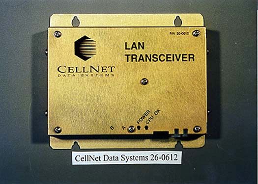
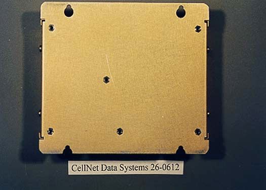
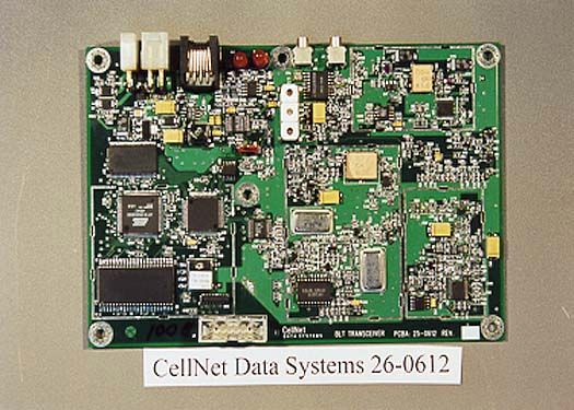
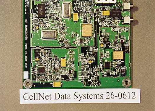
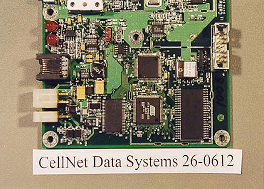
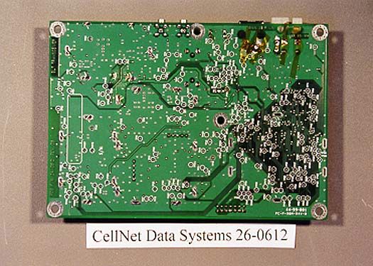
H6N26061200BLT Transceiver, Model 26-0612
CellNet Data Systems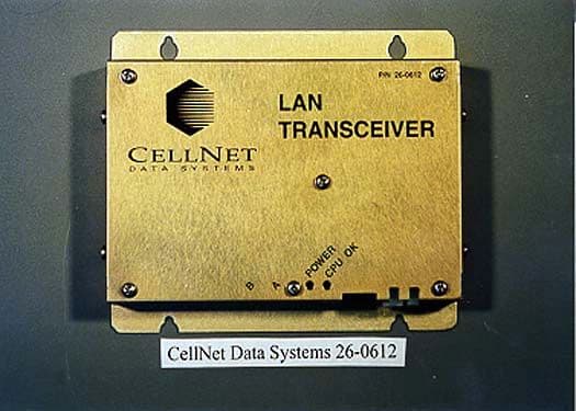
Click to zoom
Application Details
- Equipment Class
- DSS - Part 15 Spread Spectrum Transmitter
- Date of Grant
- Nov 05, 2000
- Application Purpose
- Original Equipment
- Date of Application
- Apr 03, 2000
- Equipment Note
- BLT Transceiver, Model 26-0612
- Frequency Range
- 911.58000000 - 917.58000000
- Company
- CellNet Data Systems
- Country
- United States
Documents & Files
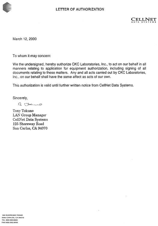
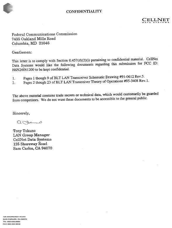
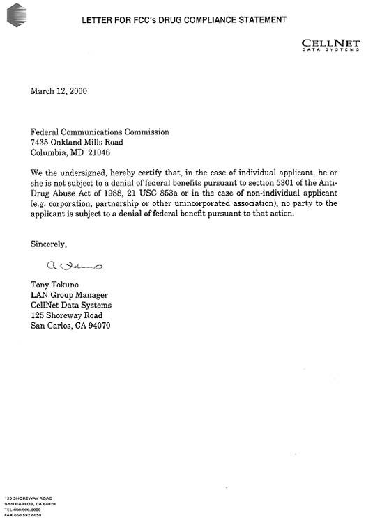

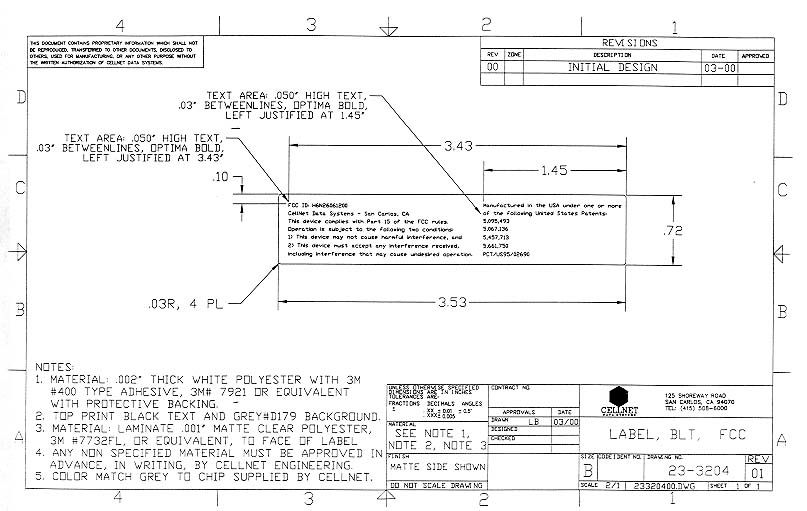
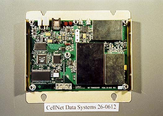
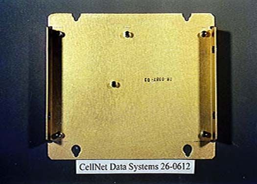
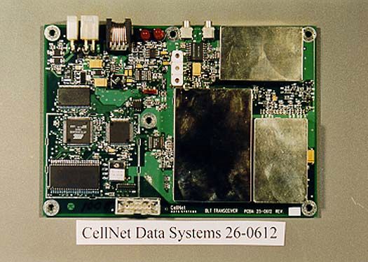
Document Text
Text extracted from the exhibit documents filed with the FCC. Open a document above to read the original.
Users Manual
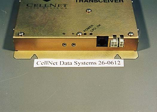
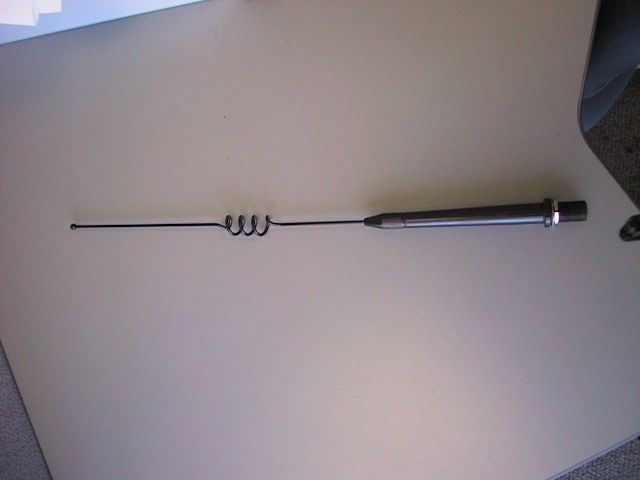
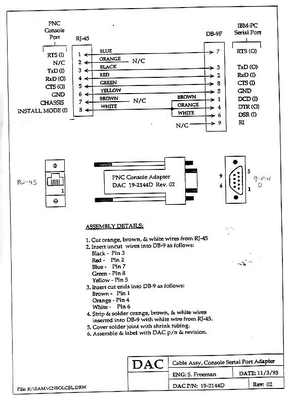
Users Manual, BLT LAN Transceiver04/18/00 Page 1 of 2 INSTALLATION OF THE BLT LAN TRANSCEIVER CellNet MODE L NUMBER: 26-00616 Notice: FCC Sec. 15.105 (b) This device has been tested and found to comply with the limits for a Class B digital device, pursuant to Part 15 of the FCC Rules. These limits are designed to provide reasonable protection against harmful interference in a residential installation. The device generates, uses, and can radiate radio frequency energy and, if not installed and used in accordance with the instruction, may cause harmful interference to radio communications. However, there is no guarantee that interference will not occur in a particular installation. If this equipment does cause harmful interference to radio or television reception which can be determined by turning the equipment off and on, the user is encouraged to try to correct the interference by one or more of the following measures: -- Reorient or relocate the antennae. -- Increase the separation between the computer and the LAN. -- Connect the computer into a power source different from that to which the LAN is connected. -- Consult CellNet Data Systems or an experienced technician for help. Caution: Any changes or modifications not expressly approved by the grantee of this device could void the users authority to operate the equipment. The BLT LAN Transceiver is built to be mounted in any location, and any orientation providing it is within the ambient temperature range of -40 to +85 degrees C and less than 95% humidity. Connect the RJ45 serial I/O to the host controller or computer using any length cable between .5 and 3 meters. The LAN can be powered by any dc power source from 10.5 to 15.5 volts capable of supplying 1 amp with less than 150 milivolts p-p of ripple into the 4 pin Molex input power connector. WARNING: The unit is protected against reverse connection for up to 2 amps for 5 seconds or forward direction up to 3KV for not more than 50 uSec. Exceeding the proceeding may result in damage to the unit. The 12 volt return (ground) connects to the pi n 4 (top pin closest to RJ45 connector) and the plus 12 volts connects to pin 3 (top pin closest to the two-pin Molex connector). According to the terms and conditions of the FCC license, the power cable must have a clamp-on ferrite filter with two turns through it - mounted within .1 meter of the LAN power connector. The filter must provide a minimum loss equivalent to Steward ferrite part number 28A2025-0A0. This is a type 28 material clamp-on core having 200 - 300 Ohms per turn at 100 MHz. Users Manual, BLT LAN Transceiver04/18/00 Page 2 of 2 The LAN is designed to receive or transmit by switching between two external whip antennae having omnidirectional gains of not more than 5 dBi. Care must be exercised when connecting or disconnecting the OSX right-angle antenna connectors: do not pull on cable; move connectors directly in or out by holding connector body. It is recommended that the coaxial connection between the BLT LAN and its antennae be kept short as practical for the mounting configuration - 0.2 to 0.5 meters. Before application of DC power, check to assure that the cover is secured by the ten screws, that the antennae, SIO and power connectors are completely engaged, and that the DC source is in the range between 10.5 and 15.5 Volts dc. A test program called CELLGRAB.EXE nicknamed GRABBER for the controller pc is available from CellNet Data Systems. Versions 3.0-46 or later are applicable. Upon application of DC power, the POWER light should illuminate followed in 2 to 5 seconds by the CPU OK light. Normal power supply current is .2 amps in the receive mode and .7 amps in transmit. If, at any time, the CPU OK light goes out, or fails to stay on, the LAN requires either the controller to issue a BREAK command over the SIO line or the DC power to be re-initialed. If the either of the two indicators remain off, check to assure DC power is adequate. If the power is ok but either of the indicators remain off, then replace, or, return the unit to a CellNet Data Systems repair facility.
Cover Letter(s)
Federal Communications Commission 7435 Oakland Mills Road Columbia, MD 21046 Re: Block diagram & manual Gentlemen/Ladies: The required block diagram(s) can be found in the document file uploaded as “Theory of Operations” and when the file is opened it is titled as “BLT LAN Transceiver Theory of Operations”. CellNet sells services, which includes the installation of their equipment. There is no user manual because the consumer or customer does not install the equipment. CellNet employees refer to the Theory of Operations (mentioned above) during installation. Sincerely, Joyce Walker Technical Report Writer CKC Laboratories, Inc.
Operational Description
BLT LAN Transceiver Processing Gain Test Procedure Part of Document Number 89-0612 Modified Date: August 26, 1999 125 Shoreway Rd., San Carlos, CA 94070 Ph.: 650 508-6000 FAX: 650 508-6700 94394 Test Name: Processing GainTest #: 5.9 Test Summary: Verifies compliance with FCC requirement for direct sequence system processing gain of at least 10 dB measured using the CW jamming margin method. Applies to Specification 2.1.10 Pass / Fail Criteria: Every point must exhibit => 12 dB processing gain. (FCC Requirement: 10 dB) Required Test Equipment: Boonton 4220A Power meter with 51175 sensor (diode sensor). HP8594E Spectrum Analyzer HP8656 Signal Generator 6-way divider and cabling for synthesizer inputs to DUTs BLT Tx Breadboard including HP8647A signal generator TOMM (tx source with a special 101 MHz sma output tap before keying portion of unit) 2 Variable Decade Attenuators, one with 0.1 dB precision Power Supply 13.5 Vdc, 5 A Fluke 87 True RMS Multi-meter 2-way and 6-way splitters and cabling PCs w ith multiple serial ports running Grabber w/ Windows95 2-way power combiner Equipment Set-up: HP8594E Spectrum Analyzer Resolution Bandwidth =3 MHz Video Bandwidth=1 MHz Sweep=50 msec Span=0 MHz Attenuation= 10 dB Variable Attenuator=as required to achieve a -80 dBm spread signal. Note:Ensure that all test equipment has been warmed up for 30 minutes and calibrated before measure- ments are taken. Signal Generator HP 9664A 6 way pwr. divider PC Controller(s) DUT DUT DUT DUT DUT 2 way pwr. div. Screen Room Temperature Chamber Transmitter Source DUT/Spec. Analyzer Variable Decade Attenuator Variable Decade Attenuator 94394 Procedure: 1. The purpose of this test is to measure the processing gain of the DUTs using the CW jamming margin method and OOK modulation. The expected result is a measure of the effective processing gain in dB, as determined from a measurement of jamming margin combined with a theoretical prediction of PSR versus post-despread SNR. For OOK modulation, theory predicts a BER of 1e-3 at a post-despread SNR of 13.8 dB. This BER corresponds to a PSR of 78%. 2. Use the test setup for the 5.8.2 and 5.8.3 portions of the receiver throughput test, with the following changes. Use a power combiner to add the output of a CW source with the output of the transmitter. The CW signal should be controllable in increments of 1dB maximum and must reach the receiver in a range of -10 to +10 dB relative to the output of the transmitter. Calibrate the signal strength from both sources, per paragraph 3.2.3. 3. Turn off the CW source and set the source transmitter for a power of -80 dBm at 917.58 MHz with 0 PPM offset. Configure the receiver (DUT) to receive on antenna port A at 917.58 MHz. Confirm that the PSR using at least 600 packets is > 98%. Turn on the CW signal and adjust it until the PSR using at least 600 packets is 78%. Record the difference in dB, with an accuracy of 0.5 dB, between the CW and transmitter powers reaching the receiver, with a higher power CW signal yielding a positive difference. 4. Compute the processing gain as PG = D + 13.8 + L , in dB, where D is the difference in CW and transmitter powers, and L is an allowance for implementation loss. Use 2 dB as the value of L. 5. Perform this test for CW frequencies ranging from 200 kHz below to 200 kHz above the transmit carrier, stepping in increments of 50 kHz. Convert the measured gains from dB to scalar, find the average, and convert back to dB. Acceptance Block: A signature below denotes that this test has met all pass criteria. Signature: David Di Salvo Date : July 99 Delta reading in dB, j ammer source level vs packet level (at DUT) dB converted to scalar, scalar averaged, average converted back to dB +25 Degrees C15. 8 (13.8dB +2dB losses) added to average Frequency Offset (KHz)AVE DUT #-200-150-100-50050100150200dB 1 dB-->3445754 5 4 Scal ar-->22.512.513.165.013.162.513.162.5120. 49 2 dB-->3445755 5 4 Scal ar-->22.512.513.165.013.163.163.162.5120. 6 3 dB-->3445754 5 4 Scal ar-->22.512.513.165.013.162.513.162.5120. 49 4 dB-->3444544 4 4 DSP Scalar-->22.512.512.513.162.512.512.512.5119.82 formula for average =ROUND(((LOG10(AVERAGE(#REF!))*10)+15.8),2)
Operational Description
Process Gain Measurement of the BLT Radio Method: The process gain of the BLT radio was measured according to FCC document 47CFR15.247(e)(1) using the method described below. A source transmitter, with the spreading code turned on, was calibrated, using a power meter, to a level of –50dBm, measured at the input to a precision attenuator in series with the input of the radio. The precision attenuator was then used to reduce this level to the middle of the dynamic range of the radio. The transmitter was then programmed to transmit CCSK packets to the radio every 100ms. At the radio demodulator, the signal power as reported by the radio was –78dBm. The system spreading code is turned off by replacing the transmitter with a CW tone generator , and the power level adjusted to the same –50dBm at the input to the precision attenuator, using the power meter. The precision attenuator was then adjusted until the power reading reported by the radio was –78dBm, the same as the reported signal level for the system spreading code on. The difference in attenuator settings between the system spreading code on and the system spreading code off is the process gain of the radio. The CW frequency was adjusted across the range 917.03MHz to 917.98MHz and the measurement repeated in order to ensure that there are no spurious effects. The set o f meas ure me nts were the n repeated with the trans mi tter set to send OOK pac kets. Diagram: Transmitter CW Generator Precision attenuator BLT Radio RF circuits A/D Conve rs io n Digita l s igna l processing circuits Power Meter Signal Power measurement Results: Attenuator setting difference, dB Frequency (MHz)CCSKOOK 917 031513 917.081513 917.131613 917.181613 917 231614 917.281714 917.331614 917.381714 917 431714 917.481714 917.531714 917.581715 917 631715 917.681815 917.731815 917.781815 917 831815 917.881715 917.931715 917.981715 Conclusion: The lowest data point is 13dB, so the processing gain of the receiver is at least 13 dB.
Operational Description
2.1) Power Measurement Power is measured by squaring the voltage. From previous reply: “The digitized IF is quadrature downconverted to I and Q baseband signals. ... At each symbol time, the accumulated results are separately squared, and then added. The results of the addition ... are also reported externally as the Signal Power.” 2.2) Diagram The test diagram in the Process Gain measurement document has been revised to show the Signal Power measurement output from the radio. 2.3) Measurement Procedure The measurement procedure is unchanged. The difference between the Signal Power reported for Spreading Code Turned On and Spreading Code Turned Off is most accurately measured by using a precision attenuator in series with the signals to move the indicated Signal Powers to the same specific value in the middle of the DSP dynamic range. What was a difference between the two Signal Powers thus becomes the difference between the attenuator settings. 3) Direct Sequence System The FCC ID H6N26061200 Transceiver is a Direct Sequence System. The RF carrier is modulated by a combination of the digital information and a higher speed code sequence. The data symbol rate is 19.266 kilosymbols per second, and the spreading code rate is 1.2137 megachips per second, in both OOK a nd CCSK operati ng modes. The spreading code biphase modulates the RF carrier in both of the da ta modulation operating modes. In the OOK operating mode, the data one’s turn the signal ON, and the data zero’s turn the signal OFF, to produce the On-Off-Keying. In the CCSK operating mode, the data bits are encoded four at a time into one-of-sixteen combinations, and the spreading code jumps to one-of- sixteen starting points in the sequence of 63 chips, and a full sequence of 63 chips spreads the carrier during each symbol duration of the Cyclic-Code-Shift-Keying. The information data rate during OOK is 19.266 kilobits per second, since there is one bit per symbol. The CCSK information data rate is four bits per symbol, or 77.064 kilobits per second.
Operational Description
Compliance with 15.247(e)1 The processing gain method complies with the exact words of 15.247 (e) 1: “The processing gain shall be determined from the ratio in dB of the signal to noise ratio with the system spreading code turned off to the signal to noise ratio with the system spreading code turned on, as measured at the demodulated output of the receiver. The CCSK receiver consists of 16 parallel correlators and power detectors, which produce 16 demodulated outputs of the receiver. The noise output values from each of the 16 are different from the others at each output time, but they have identical long-term noise power averages. Furthermore, these noise power averages are independent of any presence of an input signal, and more particularly, are independent of whether the system spreading code is turned off, or whether the system spreading code is turned on. Thus, the signal to noise ratio at the demodulated output of the receiver varies only with the signal output from the demodulated output of the receiver. The ratio in dB of the signal to noise ratio with the system spreading code turned off to the signal to noise ratio with the system spreading turned on, as measured at the demodulated output of the receiver, is exactly the ratio in dB of the signal output with the system spreading code turned off the signal output with the system spreading code turned on. The unspread CCSK modulated signal is identical to a CW signal. Since the one- of-sixteen data words selects a particular time phasing of the spreading modulation, the signal with spreading code turned off is just a CW signal, and happens to be the same CW signal for all sixteen data words. The 16 parallel receiver correlators produce 16 different received signal waveforms from doing 16 different “despreadings” of this CW waveform, but the signal power values of the 16 are equal, at the demodulated output of the receiver. The input modulation is any-one-of-sixteen, and the demodulated output is any-one-of-sixteen. The reported processing gain measurements, of the increase of signal power output with the system spreading code turned on, over the signal power output with the system spreading code turned off, measured at the demodulated output of the receiver, are an accurate determination of the processing gain.
Operational Description
Process Gain Measurement for H6N26061200 Method The processing gain is measured using the CW jamming method. The equipment arrangement is shown in the block diagram below. Process Gain Tests Configuration Procedure A signal generator is stepped in 50kHz increments across the passband of the system. At each point the generator level required to produce a bit error rate equivalent to 2.7 x 10E-3, the threshold of designed performance for the system, is recorded as the jammer level (J). The output power of the transmitter is measured at the same point and recorded as signal (S). The jammer to signal ratio (J/S) is then calculated with 20% of the worst data points discarded. The lowest remaining J/S ratio is used to calculate the processing gain using the for mula: Gp = (S/N)o + Mj + Lsys The theoretical probability of error vs. S/N is shown in the curve below, obtained from section 4.3.2 of Digital Communications, second edition, John G. Proakis, McGraw-Hill. Screen Room Source Transmitter 2 way Divide Calibrated Attn. DUT Power Meter PC Controller/ Display Unit Decade Attn. Signal Generator HP8647A SIO 16-Orthogonal Signalling Probability of Error Curve 05101520 1 . 10 6 1 . 10 5 1 . 10 4 1 . 10 3 0.01 0.1 1 SNR (dB) Probability of Error For the threshold error rate of 2.7 x 10E-3, the theoretical Signal to Noise ratio is 11.9 dB. Results With: (S/N)o = 11.9dB Lsys = 2dB Mj = 2.3dB Gp = 11.9dB + 2.3dB +2dB = 16.2dB Tabulated Jamming Test Results Pass band = 917.58MHz ± 1.2MHz Jmmr Freq. DeviationJammerSig. InJ/S Ratio (in MHz)(KHz)(dBm)(dBm)(dB) 916.381200-107.7-1113.3 916.431150-108.2-1112.8 916.481100-108.2-1112.8 916.531050-108.7-1112.3 916.581000-108.7-1112.3 916.63950-108.7-1112.3 916.68900-108.7-1112.3 916.73850-108.7-1112.3 916.78800-108.7-1112.3 916.83750-108.7-1112.3 916.88700-108.7-1112.3 916.93650-108.7-1112.3 916.98600-108.7-1112.3 917.03550-108.7-1112.3 917.08500-108.7-1112.3 917.13450-109.2-1111.8 917.18400-109.7-1111.3 917.23350-108.7-1112.3 917.28300-109.2-1111.8 917.33250-108.7-1112.3 917.38200-108.7-1112.3 917.43150-107.7-1113.3 917.48100-108.7-1112.3 917.5350-107.2-1113.8 917.580-107.2-1113.8 917.63-50-107.2-1113.8 917.68-100-106.7-1114.3 917.73-150-107.2-1113.8 917.78-200-107.7-1113.3 917.83-250-107.7-1113.3 917.88-300-107.7-1113.3 917.93-350-108.2-1112.8 917.98-400-108.2-1112.8 918.03-450-107.7-1113.3 918.08-500-106.7-1114.3 918.13-550-106.7-1114.3 918.18-600-107.2-1113.8 918.23-650-106.2-1114.8 918.28-700-106.2-1114.8 918.33-750-106.7-1114.3 918.38-800-106.2-1114.8 918.43-850-106.7-1114.3 918.48-900-106.2-1114.8 918.53-950-105.7-1115.3 918.58-1000-105.7-1115.3 918.63-1050-105.2-1115.8 918.68-1100-104.7-1116.3 918.73-1150-104.2-1116.8 918.78-1200-103.7-1117.3 Of the 49 data points, 80% have a J/S ratio of 2.3 dB or better
RF Exposure Info
Page 1 of 3 Responses to FCC Request for Information.06/06/00 1)Indicate compliance with the RF safety requirements: The BLT LAN Transceiver 26-0612 is not a portable or a mobile unit. The BLT LAN Transceiver is a stationary device mounted in an enclosure that is mounted onto power or streetlight poles. The BLT LAN transceiver does not transmit more than +30 dBm. As a part 15 Radio Frequency Device that is neither a millimeter wave device, nor an unlicensed personal communications service device, the unit is excluded by 47 CFR 1.1307 (b)(1): ..."all other facilities...are categorically excluded..." from making an exposure study. 2)Indicate the manufacturer of the spread spectrum chip: The CellNet Data Systems part number for the custom ASIC chip that generates the spread spectrum is 14-9005 and is made for CellNet Data Systems by NEC Electronics Inc. 3)The peak output power was 426.6 mW while 1 watt was requested. The designed output power for the LAN Transmitter is +27dBm ± 3dB for temperature and unit-to-unit manufacturing tolerance. The 426.6mW test unit is +26.3 dBm, which was within 0.7 dB of the nominal design center. The FCC spec 47 CFR 15.247 (B) - (1) states "...and for all direct sequence systems: 1 watt." Therefore, the requested level for max level is 30dBm (1 Watt). For CellNet's previous LAN transceiver, the DSP LAN transceiver, a peak output power of 1 watt was requested and granted. The grant was under FCC ID H6N26113097. Measured peak output power for the test unit was 420 mW or +26.2 dBm. 4)It appears that the device can operate as a computer peripheral. The RS-232 serial data interface is used for obtaining detailed information while performing tests; in actual field operation, the internal digital capability is used only to enable operation of the radio frequency part of the device, and the digital capability does not control additional functions or capabilities. So the device is excluded from the definition of a digital device, according to 47CFR 15.3 (k). However, since the requirements of 15.109 for Class B digital devices are a subset of the requirements of 15.209 for Certificated intentional radiators, the BLT Transceiver 26-0612 meets the 15.109 requirements for Class B digital devices. 5)Provide data showing compliance with Section 15.207. Page 2 of 3 The BLT LAN Transceiver does not connect to the power line hence no stand- alone 'line conducted emissions' testing is required. The BLT LAN Transceiver will either operate stand-alone while receiving dc power from a unit called the Selective Repeater or operate under the control of, and while receiving dc power from, a unit called the Micro Cell Controller. The Selective Repeater passed the conducted emissions requirements for class B digital devices under FCC ID H6N26113097. The MCC passed the conducted emissions requirements for class B digital devices under FCC ID H6N262101296. 6 & 7) Indicate compliance with Section 15.203. The device was tested with a 5 dBi antenna model number ASPG918 with a 0.25 meter cable. Verify that this is the only antenna configuration that will be used. The antenna connection to the BLT LAN Transceiver is professionally installed only by installers trained and certified by CellNet Data Systems. Therefore, 15.203 does not apply. The ASPG918 antenna has 5-dBi gain and the antenna cable, which has a type N connector on one end and a standard OSX on the other end, has at least .8 dB loss. The ASPG918 antenna is the highest gain antenna used with this unit. The antenna cable used in the test is the shortest cable used with this unit. 8)Redo power spectral density. The rate of the spreading / despreading code is 19.2655K code sequences per second. The signal carries another modulation at 642 Hz; thus, the spectral line spacing is 642 Hz which is less than 3 KHz. The testing for spectral density is performed according to FCC Public Notice 54797 for devices with spectrum line spacing equal to, or less than, 3 KHz. The spectral density was taken at a resolution bandwidth lower than 3 kHz per the public notice and the power was normalized to a 3 kHz bandwidth. The sweep time was longer than normal due to the rule that sweep time shall be (span/resolution bandwidth). As the resolution bandwidth was set low enough resolve individual lines the sweep time had to be increased. 9)Indicate theoretical process gain. What are the data rates? The chipping rate is 1.2137 Mega-chips per second, and the data symbol rate is 19.2655K code sequences per second, so the chips per symbol ratio is 63, and the theoretical process gain is 10log 63 = 17.99 dB. 10 & 11)Why more than one process gain unit? Page 3 of 3 The process gain report included with the previous submission was a result of our normal verification of manufacturability on a new product. The jammer and signal levels were measured at each receiver to insure that each unit met process gain requirements. The process gain measurements were redone and a report of testing on a single unit has been uploaded to the RF Exposure Folder on the 731 Form. The name of the file is "New Process Gain Data”. 12)OOK or CCSK modulation? OOK (on-off keying) is a worst case test condition (compared to CCSK). The difference is the switching transients occurring from turning on and off the transmit power amp during OOK transmit which could increase spurious emissions and are not required for CCSK data modulation. So, OOK data modulation was used for testing per 15.209 and 15.247. All such emissions were well within FCC specifications. The device uses both OOK and CCSK data modulation.
RF Exposure Info
Installation Manual, BLT Transceiver07/05/00 1 INSTALLATION OF THE BLT TRANSCEIVER MODEL NUMBER: 26-00612 This device complies with part 15 of the FCC Rules. Operation is subject to the following two conditions: (1) This device may not cause harmful interference, and (2) this device must accept any interference received, including interference that may cause undesired operation. In order to comply with FCC RF Exposure requirements, this device must be installed in such a way as to ensure that a minimum separation distance of 20 cm is always maintained between the antenna and all persons. The BLT LAN Transceiver is built to be mounted in any location, and any orientation providing it is within the ambient temperature range of –40 to +85 degrees C and less than 95% humidity. Connect the RJ45 serial I/O to the host controller using any length cable between 0.5 and 3 meters. The LAN can be powered by any dc power source from 10.5 to 15.5 volts capable of supplying 1 amp with less than 150 millivolts p-p of ripple into the 4-pin Molex input power connector. WARNING: The unit is protected against reverse connection for up to 2 amps for 5 seconds or forward direction up to 3kV for not more than 50 uSec. Exceeding the proceeding may result in damage to the unit. The 12-v olt return (ground) connects to pin 4 (top pin closest to RJ45 connector) and the Plus 12 volts connect to pin 3 (top pin closest to the two-pin Molex connector). According to the conditions of the FCC certification, the power cable must have a clamp-on ferrite filter with two turns through it – mounted within 0.1 meter of the LAN power connector. The filter must provide a minimum loss equivalent to Steward ferrite part number 28A2025-0A0. This is a type 28 material clamp-on core having 200 – 300 ohms-per-turn at 100 MHz. The LAN is designed to receive or transmit by switching between two external whip antennae having omnidirectional gains of not more than 5 dBi. Care must be exercised when connecting or disconnecting the OSX right- angle antenna connectors: do not pull on cable; move connectors directly in or out by holding the connector body. Installation Manual, BLT Transceiver07/05/00 2 It is recommended that the coaxial connection between the BLT LAN and its antennae be kept as short as practical for the mounting configuration: 0.2 to 0.5 meters. Before application of DC power, check to assure that the cover is secured by the ten screws, that the antennae, SIO, and power connectors are completely engaged, and that the DC source is in the range between 10.5 and 15.5 volts dc. A test program called CELLGRAB.EXE, nicknamed GRABBER, for the host controller is available; versions 3.0-46 or later are applicable. Upon application of DC power, the POWER light should illuminate, followed in 2 to 5 seconds by the CPU OK light. Normal power supply current is 0.2 amps in the receive mode and 0.7 amps in transmit. If, at any time, the CPU OK light goes out, or fails to stay on, the LAN requires either the host controller to issue a BREAK command over the SIO line, or the DC power to be re-initialed. If either of the two indicators remain off, check to assure that DC power is adequate. If the power is o.k., but either of the indicators remains off, then replace, or, return the unit to a repair facility.
Test Report
Page 1 of 48 Report No: FC00-025 CERTIFICATION TEST REPORT FOR THE BLT TRANSCEIVER, 26-0612 (TRANSMITTER PORTION ONLY) FCC PART 15.247/15.209 COMPLIANCE DATE OF ISSUE: MARCH 20, 2000 PREPARED FOR: CellNet Data Systems 125 Shoreway Road San Carlos, CA 94070 W.O. No: 73813 PREPARED BY: Joyce Walker CKC Laboratories, Inc. 5473A Clouds Rest Mariposa, CA 95338 Date of test: March 3 & 6, 2000 Report No: FC00-025 DOCUMENTATION CONTROL: _____________________________ Tracy Phillips Documentation Control Supervisor CKC Laboratories, Inc. APPROVED BY: _____________________________ Dennis Ward Director of Laboratories CKC Laboratories, Inc. This report contains a total of 48 pages and may be reproduced in full only. Partial reproduction may only be done with the written consent of CKC Laboratories, Inc. Page 2 of 48 Report No: FC00-025 TABLE OF CONTENTS Administrative Information ............................................................................................. 4 Summary Of Results........................................................................................................ 5 Equipment Under Test (EUT) Description...................................................................... 5 Measurement Uncertainty................................................................................................ 5 EUT Operating Frequency............................................................................................... 5 Peripheral Devices ........................................................................................................... 6 Report Of Measurements................................................................................................. 7 Table 1:Peak Output Power of the Fundamental................................................. 7 Table 2: Six Highest RF Conducted Emission Levels ........................................ 8 Table 3: Six Highest Radiated Emission Levels - 450kHz-30 MHz ................... 9 Table 4: Highest Radiated Emission Levels - 30-1000MHz ............................... 10 Table 5: Six Highest Radiated Emission Levels - 1-9.2GHz .............................. 11 Table A : List Of Test Equipment ................................................................................... 12 EUT Setup .......................................................................................................................13 Test Instrumentation And Analyzer Settings................................................................... 13 Table B : Analyzer Bandwidth Settings Per Frequency Range........................... 13 Spectrum Analyzer Detector Functions............................................................... 14 Peak ......................................................................................................... 14 Quasi-Peak............................................................................................... 14 Average.......................................................................…
Text truncated - open the document above for the full version.
Contact Information
Applicant
Forrest Fulton(Corporate Contact)
Technical Contact
CKC Laboratories, Inc.Tracy Phillips
[email protected]1800-500-4362
5473A Clouds Resat · Mariposa, California · United States
Non-Technical Contact
CKC Laboratories, Inc.Joyce Walker
[email protected]1-800-500-4362
Test Firm
CKC Laboratories, Inc.Steve Behm
Technical Specifications
| # | Rule Parts | Frequency Range | Power Output |
|---|---|---|---|
| 1 | 15C | 911.58 MHz - 917.58 MHz | 426.00 mW |
Other Applications from CellNet Data Systems
H6NCMM1102
Mar 29, 1999DSS - Part 15 Spread Spectrum Transmitter
Equipment Class
DSS - Part 15 Spread Spectrum TransmitterH6NCMM2200
Jul 20, 1998Machine Quantity Usage Transmitter
Equipment Class
DSS - Part 15 Spread Spectrum TransmitterH6N-26113097
Feb 08, 1998LAN Transmitter Max. output power 420 millwatts Professional installation of this transmitter is required
Equipment Class
DSS - Part 15 Spread Spectrum TransmitterH6NCMM1301
Jan 05, 1998Utility Meter Module Maximum output power: 26 mW
Equipment Class
DSS - Part 15 Spread Spectrum TransmitterH6NCMM1305
Jan 05, 1998Utility Meter Module Maximum output power: 81 mW
Equipment Class
DSS - Part 15 Spread Spectrum Transmitter