H6NCMM1102
CellNet Data Systems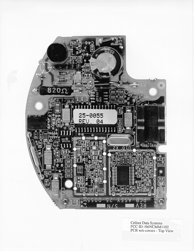
Click to zoom
Application Details
- Equipment Class
- DSS - Part 15 Spread Spectrum Transmitter
- Date of Grant
- Mar 29, 1999
- Application Purpose
- Original Equipment
- Date of Application
- Feb 02, 1999
- Frequency Range
- 917.58000000 - 917.58000000
- Company
- CellNet Data Systems
- Country
- United States
Documents & Files
Document Text
Text extracted from the exhibit documents filed with the FCC. Open a document above to read the original.
ID Label/Location Info
Description of the 26-1130 LAN Transceiver07/06/01 Page 1 of 2 RECEIVER: The LAN receiver utilizes single conversion for any one of 3 spread spectrum ISM band channels, 911.58MHz, 914.58MHz or 917.58MHz. A typical received signal approximately 1 MHz wide at it 6dB BW is amplified, filtered and down converted to a 50MHz IF. It is further filtered using two SAW filters, amplified and fed to a digital attenuator, and then to a 'A-to-D' converter. The digitized signal is hetrodyned against a digitally synthesized local oscillator fully modulated by the psudo-random code (prc), which matches the received prc. The digital IF output signal is processed by a digitally implemented bank of 11 bandpass filters having 20KHz BW. The receiver's matching code is made to 'slip' until it matches the received signal's psudo-random code. This condition is called a locked. The receiver gain for this condition is increased and a large signal appears in one of the 20KHz filters, typically increased 12 to 14 dB(process gain). The received signal's power is than ranked in the 11 frequency channels based on most power received per channel. The three strongest adjacent channels are used to adjust the agc (digital attenuator) to the point where the On-and-Off Keying (OOK) creates the one's and zeros for data reception. For the first 5ms, the received signal packet has a continuous psudo-random signal to allow the receiver to trip and lock onto the code. Then the received packet has it's carrier modulated on and off (OOK) where the data modulation has been applied to the spread carrier. After receiving the sync pulse, the received data contained within is processed into bins to be retransmitted as outgoing data. Periodically, during the data packet (every 8 bytes), the receiver's psudo-random code is re-adjusted to exactly match the received signal's code. The received data can be monitored via a RJ45 S.I.O. (serial interface) or transmitted as a relayed (repeated) message packet. TRANSMITTER: The transmit oscillator (VCO) operates directly at any of the three output frequencies 911.58MHz, 914.58MHz or 917.58MHz. Description of the 26-1130 LAN Transceiver07/06/01 Page 2 of 2 TRANSMITTER Continued: The transmit packet's timing and message format is the same as the received packet described above. While capable of transmitting continuously, the LAN transmitter duty cycle is seldom higher than 5 to 10%. The transmit output frequency is synthesized and phase locked to a TCXO at 18.205952MHz. The transmit signal is buffered, and mixed with the psudo- random code. From the mixer, the signal is routed through the preamp, which also switches the signal on and off (OOK) for the message data. From there, the signal is band-pass filtered, and routed to the final power amps. The signal is low-pass filtered and routed to the output. TRANSCEIVER: By an internal configuration control EEPROM, or control from the RJ45 SIO, the two antenna ports can be operated as follows: Port A or B one-at-a-time using a four-way diversity switch. I.E., the LAN can receive from antenna port A or B, or, the transmitter can be routed to antenna port A or B in single duplex. It can receive on one antenna port and then transmit on the other, or both the same. It can receive (and) or transmit on 'alternating ports' (switched at .5 second intervals for receive and alternating successive packets for transmit). Selection of the receive and transmit frequency is independent. I.E., the LAN can receive on 911.58MHz and then transmit at 914.58 or 917.58MHz or visa-versa. The LAN transceiver is powered by an external +10.5 to +15.5 Vdc drawing approximately .5 amps in receive and .6 amps in transmit (typically .1 more with 10.5 volt and .1 less with 15.5 volts input). The LAN transceiver operates in sheltered enclosures at temperatures from -40 to +85 degrees C ambient.
Test Report
File: R29557 Page 1 of 14 Electromagnetic Emissions Test Report and Application for Grant of Equipment Authorization pursuant to FCC Part 15, Subpart C Specifications for an Intentional Radiator on the Cellnet Data Systems Model: SLAMM Beta 2 FCC ID:H6NCMM1102 GRANTEE:Cellnet Data Systems 125 Shoreway Road San Carlos, CA 94070 TEST SITE:Elliott Laboratories, Inc. 684 W. Maude Avenue Sunnyvale, CA 94086 REPORT DATE:December 17, 1998 FINAL TEST DATE:November 24, 1998 AUTHORIZED SIGNATORY:______________________________ Mark Briggs Manager, EMC Consutling Services This report shall not be reproduced, except in its entirety, without the written approval of Elliott Laboratories, Inc. Elliott Laboratories, Inc. -- EMC DepartmentTest Report Report Date: December 17, 1998 File: R29557Page 2 of 14 pages TABLE OF CONTENTS COVER PAGE....................................................................................... 1 TABLE OF CONTENTS............................................................................ 2 SCOPE................................................................................................ 4 OBJECTIVE.......................................................................................... 4 STATEMENT OF COMPLIANCE................................................................ 4 EMISSION TEST RESULTS...................................................................... 5 LIMITS OF CONDUCTED INTERFERENCE VOLTAGE........................... 5 LIMITS OF RADIATED INTERFERENCE FIELD STRENGTH................... 5 MEASUREMENT UNCERTAINTIES.................................................. 6 COMPLIANCE EXPLANATION........................................................ 6 EQUIPMENT UNDER TEST (EUT) DETAILS................................................. 7 GENERAL................................................................................... 7 INPUT POWER............................................................................. 7 PRINTED WIRING BOARDS............................................................ 7 SUBASSEMBLIES......................................................................... 7 ENCLOSURE............................................................................... 7 SUPPORT EQUIPMENT.................................................................. 7 TEST SOFTWARE......................................................................... 7 TEST SITE............................................................................................ 8 GENERAL INFORMATION.............................................................. 8 CONDUCTED EMISSIONS CONSIDERATIONS.................................... 8 RADIATED EMISSIONS CONSIDERATIONS....................................... 8 MEASUREMENT INSTRUMENTATION...................................................... 9 INSTRUMENT CONTROL COMPUTER.............................................. 9 LINE IMPEDANCE STABILIZATION NETWORK (LISN)........................ 9 POWER METER........................................................................... 10 FILTERS/ATTENUATORS.............................................................. 10 ANTENNAS................................................................................ 10 ANTENNA MAST AND EQUIPMENT TURNTABLE.............................. 10 INSTRUMENT CALIBRATION........................................................ 10 TEST PROCEDURES.............................................................................. 11 EUT AND CABLE PLACEMENT...................................................... 11 CONDUCTED EMISSIONS............................................................. 11 RADIATED EMISSIONS................................................................. 11 SPECIFICATION LIMITS AND SAMPLE CALCULATIONS.............................. 12 CONDUCTED EMISSIONS SPECIFICATION LIMITS, SECTION 15.207.... 12 RADIATED EMISSIONS SPECIFICATION LIMITS, SECTION 15.209........ 12 SAMPLE CALCULATIONS - CONDUCTED EMISSIONS........................ 13 SAMPLE CALCULATIONS - RADIATED EMISSIONS........................... 14 EXHIBIT 1:Test Equipment Calibration Data................................................. 1 EXHIBIT 2:Test Data Log Sheets............................................................... 2 EXHIBIT 3:Radiated Emissions Test Configuration Photographs.......................... 3 EXHIBIT 4:Conducted Emissions Test Configuration Photographs....................... 5 EXHIBIT 5:Proposed FCC ID Label & Label Location...................................... 7 EXHIBIT 6:Detailed Photographs of Cellnet Data Systems Model SLAMM Beta 2 Construction 8 EXHIBIT 7:Operator's Manual for Cellnet Data Systems Model SLAMM Beta 2........ 9 EXHIBIT 8:Block Diagram of Cellnet Data Systems Model SLAMM Beta 2............ 10 EXHIBIT 9:Schematic Diagrams for Cellnet Data Systems Model SLAMM Beta 2..... 11 EXHIBIT 10:Theory of Operation for Cellnet Data Systems Model SLAMM Beta 2..... 12 Elliott Laboratories, Inc. -- EMC DepartmentTest Report Report Date: December 17, 1998 File: R29557Page 3 of 14 pages SCOPE An electromagnetic emissions test has been performed on the Cellnet Data Systems electric meter module model SLAMM Beta 2 pursuant to Subpart C of Part 15 of FCC Rules for intentional radiators. Conducted and radiated emissions data has been collected, reduced, and analyzed within this report in accordance with measurement guidelines set forth in ANSI C63.4-1992 as outlined in Elliott Laboratories test procedures. The intentional radiator above has been tested in a simulated typical installation to demonstrate compliance with the relevant FCC performance and procedural standards. Final system data was gathered in a mode that tended to maximize emissions by varying orientation of EUT, orientation of power and I/O cabling, antenna search height, and antenna polarization. Every practical effort was made to perform an impartial test using appropriate test equipment of known calibration. All pertinent…
Text truncated - open the document above for the full version.
Contact Information
Applicant
Forrest Fulton(Corporate Contact)
Technical Contact
Elliott Laboratories IncMark Briggs
[email protected]408-245-7800
684 W. Maude Ave. · Sunnyvale, California · United States
Test Firm
Elliott Laboratories LLCDavid Bare
Technical Specifications
| # | Rule Parts | Frequency Range | Power Output |
|---|---|---|---|
| 1 | 15C | 917.58 MHz - 917.58 MHz | 72.40 mW |
Other Applications from CellNet Data Systems
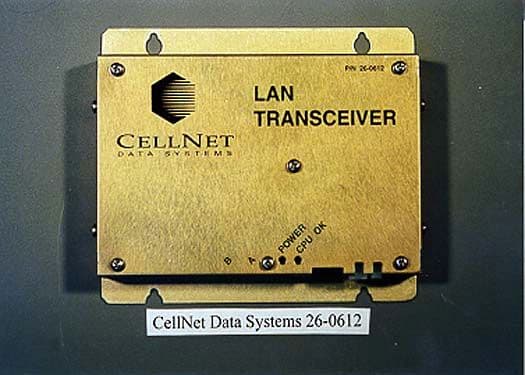
H6N26061200
Nov 05, 2000BLT Transceiver, Model 26-0612
Equipment Class
DSS - Part 15 Spread Spectrum TransmitterH6NCMM2200
Jul 20, 1998Machine Quantity Usage Transmitter
Equipment Class
DSS - Part 15 Spread Spectrum TransmitterH6N-26113097
Feb 08, 1998LAN Transmitter Max. output power 420 millwatts Professional installation of this transmitter is required
Equipment Class
DSS - Part 15 Spread Spectrum TransmitterH6NCMM1301
Jan 05, 1998Utility Meter Module Maximum output power: 26 mW
Equipment Class
DSS - Part 15 Spread Spectrum TransmitterH6NCMM1305
Jan 05, 1998Utility Meter Module Maximum output power: 81 mW
Equipment Class
DSS - Part 15 Spread Spectrum Transmitter