HBW0133-1Part 15 Spread Spectrum Transmitter Commercial Door Operator Radio
Chamberlain Group LLC, The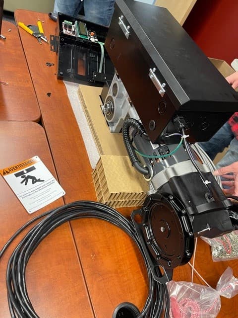
Click to zoom
Application Details
- Equipment Class
- DSS - Part 15 Spread Spectrum Transmitter
- Date of Grant
- Feb 23, 2021
- Application Purpose
- Original Equipment
- Date of Application
- Jan 23, 2021
- Equipment Note
- Part 15 Spread Spectrum Transmitter Commercial Door Operator Radio
- Frequency Range
- 902.25000000 - 926.75000000
- Company
- Chamberlain Group LLC, The
- Country
- United States
Documents & Files
Document Text
Text extracted from the exhibit documents filed with the FCC. Open a document above to read the original.
Users Manual
HPH1 High Performance Variable Speed Operator INSTALLATION MANUAL LiftMaster 300 Windsor Drive Oak Brook, IL 60523 LISTED LISTED 0 12 24 36 48 60 72 84 96 108 120 132 144 156 168 180 192 204 216 CAMERA-READY LOGOTYPE OF THE UL LISTING MARK FOR CANADA AND THE U.S. These Marks are registered by Underwriters Laboratories Inc. U L US LISTED C U L US LISTED C U L US LISTED C U L US LISTED C U L US C LISTED C US U L U L US C LISTED U L US C LISTED U L US C LISTED The minimum height of the registered trademark symbol shall be 3/64 of an inch. When the overall diameter of the UL Mark is less than 3/8 of an inch, the trademark symbol may be omitted if it is not legible to the naked eye. Please note: Not all of these elements should be used together with the same UL Mark. The word “LISTED” would only be used once — either to the right of or below the UL Mark (as shown). The font for all letter forms is Helvetica Condensed Black, except for the trademark symbol , which is Helvetica Condensed Medium. No other fonts are acceptable. RELATIVE DESIGN & PROPORTIONS OF THE UL LISTING MARK FOR CANADA AND THE U.S. KEY TO DIMENSIONS UL Mark A B C D E F G H 8 units 13 units 14 units 15 units 17 units 20 units 24 units 29 units “C” and “US” “LISTED” P Q R T 34 units 56 units 75 units 201 units I J K L M N 0 30 units 35 units 59 units 85 units 87 units 176 units 216 units N PPR JF C F AFGJ M O Q K G B D H E I F P P T I P T L 200-195S 10M/8/98 HPH1, 1.25 HP (120V/240V Single Phase & 230V 3 Phase) HPH2, 1.25 HP (460V/575V Three Phase, via stepdown transformer) NOT FOR RESIDENTIAL USE • Please read this manual and the enclosed safety materials completely, prior to installation and use! • This product is to be installed and serviced by a trained door systems technician ONLY. • These operators are compatible with myQ ® Smart Facility Accessƒ and Security+ 2.0 ® accessories. Need QR code for wiring diagram from J.P. Request: ‘add something for WiFi’ no content supplied 2 TO REDUCE THE RISK OF SEVERE INJURY OR DEATH: IMPORTANT INSTALLATION INSTRUCTIONS 1. READ AND FOLLOW ALL INSTALLATION WARNINGS AND INSTRUCTIONS. 2. Install door operator ONLY on a properly balanced and lubricated door. An improperly balanced door may NOT reverse when required and could result in SEVERE INJURY or DEATH. 3. ALL repairs to cables, spring assemblies and other hardware MUST be made by a trained door systems technician BEFORE installing an operator. 4. Disable ALL locks and remove ALL ropes connected to a door BEFORE installing an operator to avoid entanglement. 5. Install an operator, a minimum of 8 feet (2.44 m) from the floor. 6. NEVER connect a door operator to a power source until instructed to do so. 7. NEVER wear watches, rings or loose clothing while installing or servicing an operator. They could be caught in the door or operator mechanisms. 8. Install a control station and/or controller: • within sight of the door • out of reach of children and at a minimum height of 5 feet (1.5 m) above floors, landings, steps, or any other adjacent walking surface • away from ALL moving parts of the door 9. Install the control station far enough from the door to prevent the user from coming in contact with the door while operating the controls. 10. Install the entrapment warning placard on the wall next to the control station in a prominent location, visible from the door. 11. Instruct the end user on the operation of the manual release. 12. Upon completion of installation, test the entrapment protection device(s). 13. SAVE THESE INSTRUCTIONS. When you see these Safety Symbols and Signal Words on the following pages, they will alert you to the possibility of serious injury or death if you do not comply with the warnings that accompany them. The hazard may come from something mechanical or from electric shock. Read the warnings carefully. Mechanical Electrical IMPORTANT NOTES: • BEFORE attempting to install, operate or maintain the commercial door operator, you must read and fully understand this manual and follow all safety instructions. • DO NOT attempt repair or service of a commercial door operator unless you are an Authorized Service Technician. • A commercial door operator should only be installed on a properly balanced door only. Ensure door is properly balanced prior to installation. SAFETY INFORMATION ENTRAPMENT PROTECTION DEVICES: LiftMaster Monitored Entrapment Protection (LMEP) Monitored photoelectric sensors and/or door edge sensors are required for any momentary contact to close modes of operation. See page 20› for additional information. Refer to the accessories page 45, ‘Entrapment Protection Devices’ for available options. When you see this Signal Word on the following pages, it will alert you to the possibility of damage to your door and/or the door operator if you do not comply with the cautionary statements that accompany it. Read them carefully. Request: ‘change to wall controller’ standardized terminology calls for ‘door control’ or ‘control station’ currently left as is 3 TABLE OF CONTENTS SAFETY INFORMATION 3 OPERATOR 4-9 Overview ....................................4-6 Carton Inventory ...............................6 Operator Specifications ........................7-10 INSTALLATION................................11-13 Determine Mounting Location ....................11 Mounting the Operator..........................12 Mounting the Door Control Station (Controller).......13 WIRING 14-20 Wiring the Power Head .......................14-16 Wiring the Encoder ............................16 Wiring Incoming Power to the Controller ...........18 Wiring Optional Accessories ...................18-19 Wiring the 3-Phase Step Down Transformer.........19 LiftMaster Monitored Entrapment Protection (LMEP) ..20 Install the LiftMaster Monitored Entrapment Protection (LMEP) Devices ......................20 Wire the LiftMaster Monitored Entrapment Protection (LMEP) Devices ......................20 PROGRAMMING ..........................21-…
Text truncated - open the document above for the full version.
Attestation Statements
Agency Authorization Letter December 16, 2020 Elite Ele ctronic Engineering, Inc 1516 Centre Circle Downers Grove, IL 60515 To whom it may concern: Elite Electronic Engineering, Inc is authorized to act on our behald, until otherwise notified, for applications to Elite Electronic Engineering, Inc. We certify that we are not subject to denial of federal benefits, that includes FCC benefits, pursuant to Section 5301 of the Anti- Drug Abuse Act of 1988, U.S.C. 862. Further, no party, as defined in 47 CFR 1.2002 (b) to the application is subject to denial of federal benefits, that includes FCC benefits. Thank you. Regards, Barbara Kelkhoff Regulatory Manager
Cover Letter(s)
Federal Communication Commission Equipment Authorization Division Application Processing Branch 7435 Oakland Mills Road Columbia, Maryland 21046 December 16, 2020 FCC ID: HBW0133-1 Request for Confidentiality In accordance with 47 C.F.R. Section 0.457 and 0.459, we, Chamberlain Group, Inc., hereby request confidentiality for the theory of operation, parts list, user manual, block diagram and schematic presented for certification. In support of the Request for Confidentiality, the following is stated: Enclosed within this application is technical information which we deem to be trade secrets and proprietary. If made public, the information might be used to our disadvantage. To assist in assuring that we receive the full value of our product and protect its competitive posture, we respectfully request this grant of confidentiality. I would appreciate your prompt attention to the submittal. If there are any questions, please call me at 630-993-6306 or send a fax to 630-516-6863. Sincerely, Barbara Kelkhoff Regulatory Manager Chamberlain Group, Inc. 300 Windsor Dr. Oak Brook, IL 60523
ID Label/Location Info
COMMERIAL DOOR OPERATOR 41B6 Rev A
Test Report
For The Chamberlain Group, Inc. 300 Windsor Dr. Oak Brook, IL 60523 P.O. Number4900067654 Date ReceivedDecember 9, 2020 Date TestedDecember 9 - 17, 2020 Test PersonnelT ylar Jozefczyk Specification FCC "Code of Federal Regulations" Title 47, Part 15, Subpart C, Sections 15.207 and 15.247 for Frequency Hopping Spread Spectrum Intentional Radiators within the band 902–928MHz FCC “Code of Federal Regulations” Title 47, Part15, Subpart 15B, Section 15.107 and 15.109 for Receivers Industry Canada RSS-247 Industr y Canada RSS-GEN Test Report B y: T ylar Jozefczyk EMC En gineer Requested B y:David Bornemann The Chamberlain Group, Inc. Approved By: Ra ymond J. Klouda Registered Professional Engineer of Illinois - 44894 Engineering Test Report No. 2004712-01 Measurement of RF Interference from the Model No. HPH1 Wall Control Station Transceiver Engineering Test Report No. 2004712-01 THIS REPORT SHALL NOT BE REPRODUCED, EXCEPT IN FULL, WITHOUT THE WRITTEN APPROVAL OF ELITE ELECTRONIC ENGINEERING INCORPORATED. Page 2 of 80 TABLE OF CONTENTS PARAGRAPH DESCRIPTION OF CONTENTS PAGE NO. 1. INTRODUCTION ............................................................................................................................................... 5 1.1 Scope of Tests .......................................................................................................................................... 5 1.2 Purpose ..................................................................................................................................................... 5 1.3 Deviations, Additions and Exclusions ....................................................................................................... 5 1.4 EMC Laboratory Identification .................................................................................................................. 5 1.5 Laboratory Conditions ............................................................................................................................... 5 2. APPLICABLE DOCUMENTS ............................................................................................................................ 5 3. EUT SET-UP AND OPERATION ...................................................................................................................... 6 3.1 General Description .................................................................................................................................. 6 3.1.1 Power Input .......................................................................................................................................... 6 3.1.2 Peripheral Equipment ........................................................................................................................... 6 3.1.3 Interconnect Cables ............................................................................................................................. 6 3.1.4 Grounding ............................................................................................................................................. 6 3.2 Operational Mode ..................................................................................................................................... 6 3.3 EUT Modifications ..................................................................................................................................... 7 4. TEST FACILITY AND TEST INSTRUMENTATION .......................................................................................... 7 4.1 Shielded Enclosure ................................................................................................................................... 7 4.2 Test Instrumentation ................................................................................................................................. 7 4.3 Calibration Traceability ............................................................................................................................. 7 4.4 Measurement Uncertainty ......................................................................................................................... 7 5. TEST PROCEDURES ....................................................................................................................................... 8 5.1 Receiver .................................................................................................................................................... 8 5.1.1 Powerline Conducted Emissions .......................................................................................................... 8 5.1.1.1 Requirements .............................................................................................................................. 8 5.1.2 Radiated Measurements ...................................................................................................................... 8 5.1.2.1 Requirements .............................................................................................................................. 8 5.1.2.2 Procedures .................................................................................................................................. 8 5.1.2.1 Results ......................................................................................................................................... 9 5.2 Transmitter ................................................................................................................................................ 9 5.2.1 Powerline Conducted Emissions .......................................................................................................... 9 5.2.1.1 Requirements .............................................................................................................................. 9 5.2.2 20dB Bandwidth .................................................................................................................…
Text truncated - open the document above for the full version.
Test Setup Photos
Engineering Test Report No. 2004712-01 Page 19 of 80 Figure 3 Test Setup for Radiated Emissions – 30MHz to 1GHz, Horizontal Polarization Test Setup for Radiated Emissions – 30MHz to 1GHz, Vertical Polarization Engineering Test Report No. 2004712-01 Page 20 of 80 Figure 4 Test Setup for Radiated Emissions (Receiver) – 1 to 10GHz, Horizontal Polarization Test Setup for Radiated Emissions (Receiver) – 1 to 10GHz, Vertical Polarization Engineering Test Report No. 2004712-01 Page 21 of 80 Figure 5 Test Setup for Radiated Emissions (Transmitter) – 1 to 10GHz, Horizontal Polarization Test Setup for Radiated Emissions (Transmitter) – 1 to 10GHz, Vertical Polarization
Contact Information
Applicant
Thomas DeSilvia(Director Corporate Compliance)
Technical Contact
The Chamberlain Group, Inc.Barbara Kelkhoff
[email protected]630 993 6306
300 Windsor Dr. · Oak Brook · United States
Non-Technical Contact
The Chamberlain Group, Inc.Barbara Kelkhoff
[email protected]630 993 6306
Test Firm
Elite Electronic Engineering Inc.Kevin Halpin
Technical Specifications
| # | Rule Parts | Frequency Range | Power Output |
|---|---|---|---|
| 1 | 15C | 902.25 MHz - 926.75 MHz | 47.00 mW |
Other Applications from Chamberlain Group LLC, The

HBW73514
Jul 06, 2026iDock Link 2
Equipment Class
DSS - Part 15 Spread Spectrum TransmitterHBW-VKP2K
Jun 23, 2026SMART GARAGE VIDEO KEYPAD
Equipment Class
DTS - Digital Transmission System
HBWCHM1
Dec 03, 2025Wireless Chime
Equipment Class
DTS - Digital Transmission SystemHBWN519
Oct 10, 2024VEHICULAR GATE OPENER
Equipment Class
DSS - Part 15 Spread Spectrum TransmitterHBWN329
Sep 22, 2024Handheld Remote
Equipment Class
DSC - Part 15 Security/Remote Control Transmitter