HBW0196CAPXM
Chamberlain Group LLC, The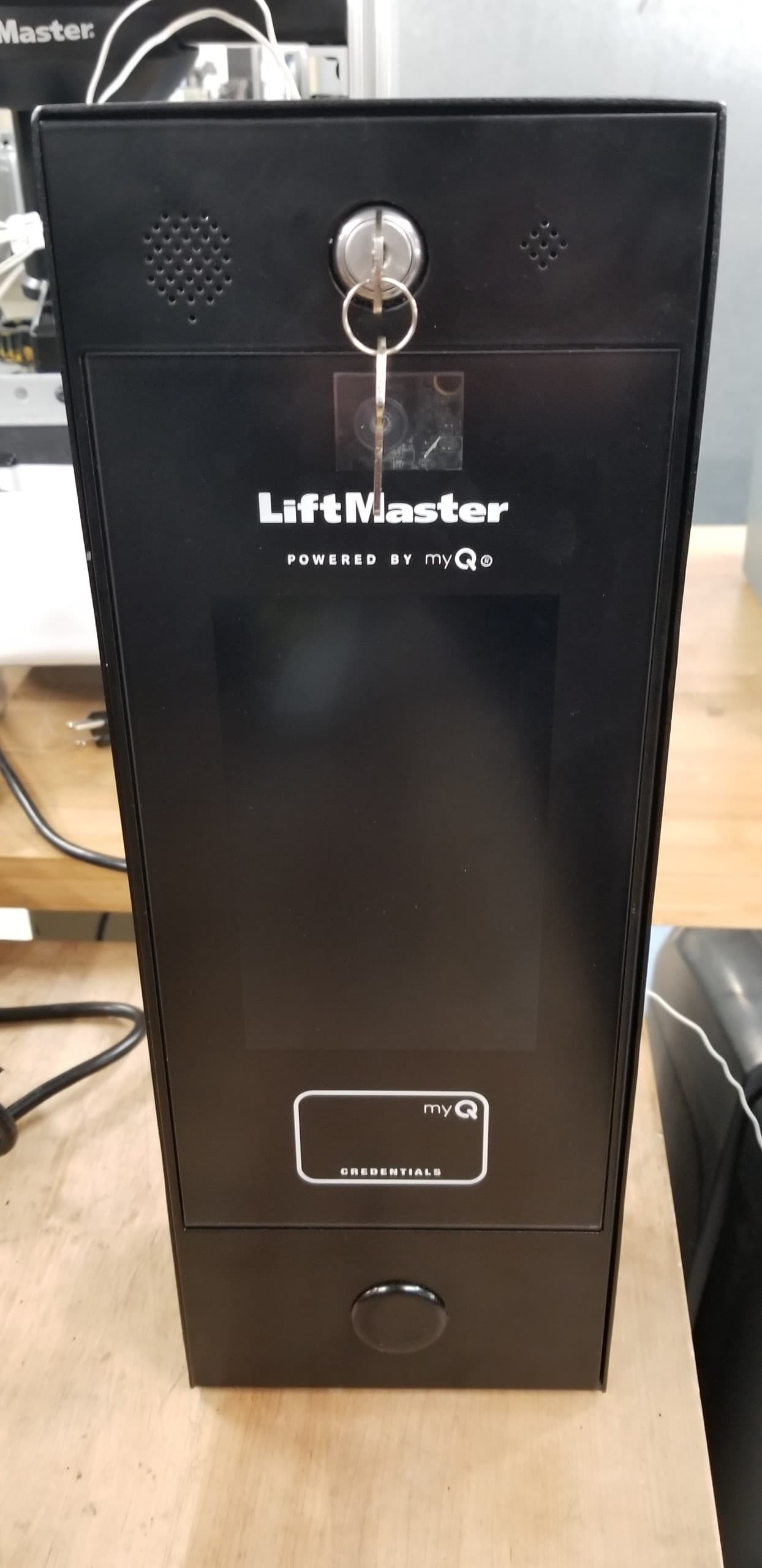
Click to zoom
Application Details
- Equipment Class
- DSS - Part 15 Spread Spectrum Transmitter
- Date of Grant
- May 10, 2021
- Application Purpose
- Original Equipment
- Date of Application
- May 05, 2021
- Equipment Note
- CAPXM
- Frequency Range
- 902.24000000 - 926.74000000
- Company
- Chamberlain Group LLC, The
- Country
- United States
Documents & Files
Document Text
Text extracted from the exhibit documents filed with the FCC. Open a document above to read the original.
Users Manual
1 myQ ® Business™ Smart Video Intercom M INSTALLATION MANUAL Model CAPXM 2 To reduce the risk of SEVERE INJURY or DEATH: • Disconnect power at the fuse box BEFORE proceeding. • To AVOID damaging gas, power or other underground utility lines, contact underground utility locating companies BEFORE digging. • ALL electrical connections MUST be made by a qualified individual. • ALL power and control wiring MUST be run in separate conduit. • All power wiring should be on a dedicated circuit and well protected. The location of the power disconnect should be visible and clearly labeled. • The CAPXM shall be installed in accordance with the National Electrical Code and all local codes. To protect against fire and electrocution: • Disconnect power BEFORE installing or servicing CAPXM. • NEVER connect a keypad/reader or lock to doors without first consulting the applicable fire code. • You MUST consult with, and get approval from, local fire officials BEFORE installing locks or devices on ANY doors that may be fire exits. • Use of egress push buttons may not be legal. Single action exits may be required. • ALWAYS obtain proper permits and approvals in writing BEFORE installing equipment. DO NOT INSTALL THE SYSTEM IN THE FAIL SECURE MODE UNLESS PERMITTED BY THE LOCAL AUTHORITY HAVING JURISDICTION. Doing so may cause interference with the operation of panic hardware. Safety Safety Symbol and Signal Word Review When you see these Safety Symbols and Signal Words on the following pages, they will alert you to the possibility of serious injury or death if you do not comply with the warnings that accompany them. The hazard may come from something mechanical or from electric shock. Read the warnings carefully. When you see this Signal Word on the following pages, it will alert you to the possibility of damage to your property or product if you do not comply with the cautionary statements that accompany it. Read them carefully. MECHANICAL ELECTRICAL WARNING: This product can expose you to chemicals including lead, which are known to the State of California to cause cancer or birth defects or other reproductive harm. For more information go to www.P65Warnings.ca.gov. 3 PRE-INSTALLNETWORKINSTALLACCESS CONTROLINTRODUCTION INTRODUCTIONPRE-INSTALLNETWORKINSTALLACCESS CONTROL INTRODUCTIONPRE-INSTALLNETWORKINSTALLACCESS CONTROL INTRODUCTIONPRE-INSTALLNETWORKINSTALLACCESS CONTROL INTRODUCTIONPRE-INSTALLNETWORKINSTALLACCESS CONTROL INTRODUCTION CAPXM Overview ..........................................................4 Control Board Overview ................................................5 Door Board Overview ....................................................6 Carton Inventory ...........................................................7 Tools Needed ................................................................7 Dimensions ...................................................................8 System Specifications ...................................................8 Wire Specifications .......................................................9 Internet Requirements.................................................10 PRE-INSTALL 1 Setup a myQ ® Business™ Account .............................11 INSTALL 2 Remove Knockouts .....................................................12 Mount the CAPXM .......................................................13 Install the Ground........................................................14 Connect Power ............................................................15 NETWORK 3 Connect Internet ..........................................................16 Validate Setup .............................................................16 ACCESS CONTROL 4 Gate Access (Wired)....................................................17 Gate Access (Wireless) ...............................................18 Door Access ................................................................19 RFID Reader ................................................................20 Wiegand Output ..........................................................21 Postal Lock .................................................................21 Wiring Diagram ...........................................................22 Repair Parts ................................................................23 Accessories .................................................................23 Configuration Sheet.....................................................24 Legal Disclaimers ........................................................25 Warranty .....................................................................26 For myQ ® Business™ programming, please visit www.myqbusiness.com 4 PRE-INSTALLNETWORKINSTALLACCESS CONTROLINTRODUCTION INTRODUCTIONPRE-INSTALLNETWORKINSTALLACCESS CONTROL INTRODUCTIONPRE-INSTALLNETWORKINSTALLACCESS CONTROL INTRODUCTIONPRE-INSTALLNETWORKINSTALLACCESS CONTROL INTRODUCTIONPRE-INSTALLNETWORKINSTALLACCESS CONTROL CAPXM Overview Smart Video Intercom M (Model CAPXM) is a cloud based access control solution that includes an integrated video camera enabling advanced video features. DISPLAY (TOUCHSCREEN) SPEAKER SPEAKER LOCK PROVISION FOR POSTAL LOCK PROVISION FOR POSTAL LOCK PROVISION FOR CARD READER CAMERA WINDOW MICROPHONE TETHER MICROPHONE VIDEO CAMERA CONTROL BOARD DOOR CONTROL BOARD 5 + Voltage Input Admin ModeNot Used + 12 Volts + 5 Volts + 3.3 Volts + 3.4 Volts Diagnostic PRE-INSTALLNETWORKINSTALLACCESS CONTROLINTRODUCTION INTRODUCTIONPRE-INSTALLNETWORKINSTALLACCESS CONTROL INTRODUCTIONPRE-INSTALLNETWORKINSTALLACCESS CONTROL INTRODUCTIONPRE-INSTALLNETWORKINSTALLACCESS CONTROL INTRODUCTIONPRE-INSTALLNETWORKINSTALLACCESS CONTROL Control Board Overview Power + - Expansion Wi-Fi ® Antenna Connection Speaker Microphone Touch Panel Display Data Switches and Diagnostic LEDs Coin Cell Battery Security+ 2.0 ® Radio Antenna EthernetUSB USB (Camera) Postal Lock Door Board FRONT VIEWBACK VIEW 6 PRE-INSTALLNETWORKINSTALLACCESS …
Text truncated - open the document above for the full version.
Users Manual
22 Wiring Diagram Not responsible for conflicts between the information listed in the wiring diagram and the requirements of your local building codes. The information is for suggested use ONLY. Check your local codes BEFORE installation. Yellow White Green Black White Red Black RedBlack Purple Not to scale (Back of Control Board) (Back of Control Board) Red Ethernet USB Black White Door BoardUSB Camera Postal Lock Switch Power Supply Ethernet Connection Internal Wi-Fi ® Antenna Optional External Wi-Fi ® Antenna Optional MyQ ® Cable Extension Kit MicrophoneSpeaker Faceplate/Screen Display Data Touch Panel 2323 Accessories ITEMPART NUMBER Cam and Lock KitK41-0215-000 Front Panel with Display Kit, CAPXMK41-0216-000 Control Board, CAPXMK41-0217-000 Microphone Kit, CAPXMK41-0223-000 Postal Lock Switch, CAPXMK41-0219-000 Rear Housing Assembly, CAPXMK41-0220-000 Wiring Kit, CAPXMK41-0221-000 Speaker Kit, CAPXMK41-0222-000 Power Supply KitK41-0227-000 Door Board and CoversK001D8478 USB Camera KitCAPXLCAM ITEMPART NUMBER Reader Multi-class SE RP10 Mini MullionLMMC-MINI Wi-Fi ® Antenna KitK76-38957 Radio Antenna KitK76-38958 Radio Antenna Extension (15 foot)86LM Wi-Fi ® Antenna Extension (15 foot)WFAEXT Wi-Fi ® /Bluetooth ® External AntennaWFBTEXT ESARM AntennaXMANTKIT Internal Proximity ReaderXMRDRKIT Wiegand Keypad/Proximity ReaderKPR2000* Connected Access Portal 2 DoorCAP2D Cellular 4G/LTE Modem with Wi-Fi ® CAPCELL All LiftMaster ® myQ ® /UL325 compatible gate operators Passport 3-Button Visor Remote Control MAX PPV3M Passport 3-Button Mini Remote Control MAX PPK3M Passport 3-Button Mini Proximity Remote Control MAXPPK3PHM Passport Lite 1-Button Visor RemotePPLV1-X** Passport Lite 1-Button Key Chain RemotePPLK1-X** Passport Lite 1-Button Mini Proximity RemotePPLK1PH-X** RFID Long Range ReaderLMSC1000 RFID Universal Tag (windshield/headlamp)LMUNTG RFID Vehicle Hang TagLMHNTG Repair Parts * KPR2000 is not UL listed to UL 294. It cannot be used as primary means of granting or denying access but only for supplemental use. ** Available in 10 and 100 packs, replace X with 10 or 100 NOTE: A current list of compatible readers and keypads is maintained at LiftMaster.com. If you have a specific model of reader or keypad that is not listed on the LiftMaster website, please contact LiftMaster Technical Support to determine compatibility. 24 Configuration Sheet Record device information and configuration settings below. CAPXM Name: NOTE: Any user of the system is subject to the terms outlined in the product EULA. Notes: DEVICE CONFIGURATION: DOOR 1 DOOR/GATE NAME: INPUTS WIEGANDREXSTATUS EOL (Y / N) OUTPUTS PRIMARY RELAYAUXILIARY RELAY N.O.N.C.N.O.N.C. Notes: DOOR 2 DOOR/GATE NAME: INPUTS WIEGANDREXSTATUS EOL (Y / N) OUTPUTS PRIMARY RELAYAUXILIARY RELAY N.O.N.C.N.O.N.C. Notes: 25 Legal Disclaimers Canada-Underwriters Laboratories Compliance The CAPXM shall be installed in accordance with Part 1 of the Canadian Electrical Code. Documentation Disclaimer and Restrictions Information in this document is subject to change without notice and does not represent a commitment on the part of LiftMaster. For the most up-to-date information, visit LiftMaster.com. This document and the data herein shall not be duplicated, used or disclosed to others for procurement or manufacturing, except as authorized with the written permission of LiftMaster. The information contained within this document or within the product itself is considered the exclusive property of LiftMaster. All information in this document or within the hardware and software product themselves is protected by the copyright and/or other intellectual property laws of the United States. UL 294 Access Control Unit Endurance: Level 3, Line security: Level 1, Destructive Attack: Level 1, Power Standby: Level 1 NOTICE: This device complies with part 15 of the FCC rules and Innovation, Science and Economic Development Canada license-exempt RSSs. Operation is subject to the following two conditions: (1) this device may not cause harmful interference, and (2) this device must accept any interference received, including interference that may cause undesired operation. Any changes or modifications not expressly approved by the party responsible for compliance could void the user’s authority to operate the equipment. This device must be installed to ensure a minimum 20 cm (8 in.) distance is maintained between users/bystanders and device. This device has been tested and found to comply with the limits for a Class B digital device, pursuant to part 15 of the FCC rules and Industry Canada ICES standard. These limits are designed to provide reasonable protection against harmful interference in a residential installation. This equipment generates, uses and can radiate radio frequency energy and, if not installed and used in accordance with the instructions, may cause harmful interference to radio communications. However, there is no guarantee that interference will not occur in a particular installation. If this equipment does cause harmful interference to radio or television reception, which can be determined by turning the equipment off and on, the user is encouraged to try to correct the interference by one or more of the following measures: - Reorient or relocate the receiving antenna. - Increase the separation between the equipment and receiver. - Connect the equipment into an outlet on a circuit different from that to which the receiver is connected. - Consult the dealer or an experienced radio/TV technician for help. NOTICE: When mounting the CAPXM at a pedestrian entrance, to meet ADA compliance, mount the top of the CAPXM screen no higher than 54 inches from the ground. NOTE: When installing CAPXM, please refer to the local jurisdiction for any specific requirements such as physical signage that may be required. 26 Warranty LiftMaster (“Seller”) warrants to the first purchaser of this product, for the structure in which this product is originally installed, that…
Text truncated - open the document above for the full version.
Users Manual
20 Schéma de câblage du lecteur RFID LMSC1000 de LiftMaster RF LP PWR RESET Serial PowerLoop Dry ContWiegand SET/ERR SER I SER 0 WO DC SETUP LOOP 8SEC 4SEC 2SEC 1SEC 1 2 3 4 5 6 PWR SET Boucle de détection de mise en service (facultative) Régler le commutateur 5 à « ON » pour activer. Lecteur RFID LMSC1000 Transformateur de puissance Noir avec pointillé Noir uni Rouge Noir Normalement ouvert Normalement ouvert Éclairage à faible tension Boucle de détection de mise en service Neutre Neutre 24 V c. a./c. c. 1 A max. Verte Blanc Jaune Blanc Les fils gris, bleu et brun du lecteur RFID ne sont pas utilisés. Verte Noir Panneau de porte 1 Porte 1Porte 2 ENTRÉE WIEGAND RELAIS PRIMAIRE RELAIS AUXILIAIRE RELAIS AUXILIAIRE DEMANDE DE SORTIE SORTIE WIEGAND DEMANDE DE SORTIE ÉTAT ÉTAT RELAIS PRIMAIRE ON ENTRÉE WIEGAND ON - OFF +12 V - 12 V c. c. (masse) +12 V - 12 V c. c. (masse) ENTR SÉR SORT SÉR GND DON- NÉES 1 DON- NÉES 0 GND GND BCLE_ INL BCLE_ INh AUCUNE CONN A B Actionneur de barrière Témoin lumineux externe de faible tension (facultatif) PRÉINSTALLATIONRÉSEAUINSTALLATIONCONTRÔLE D'ACCÈSINTRODUCTION PREINSTALACIÓNREDINSTALACIÓNCONTROL DE ACCESOINTRODUCCIÓN PRÉINSTALLATIONRÉSEAUINSTALLATIONCONTRÔLE D'ACCÈSINTRODUCTION PRÉINSTALLATIONRÉSEAUINSTALLATIONCONTRÔLE D'ACCÈSINTRODUCTION PRÉINSTALLATIONRÉSEAUINSTALLATIONCONTRÔLE D'ACCÈSINTRODUCTION PRÉINSTALLATIONRÉSEAUINSTALLATIONCONTRÔLE D'ACCÈSINTRODUCTION 21 Sortie Wiegand PORTE 1 Données-0 Masse Données 1 Entrée Wiegand de système d’accès de tierce partie (Ce dispositif/lecteur doit être homologué à la norme UL 294.) Déconnecter l’alimentation AVANT d’effectuer toute connexion électrique. Le CAPXM offre une sortie Wiegand capable d’une transmission de 26 bits des données suivantes : • Appel réussi avec accès accordé par le résident. Le CAPXM fournira un code d’installation myQ ® Business™ précisé suivi du code de répertoire du résident ayant accordé l’accès. et/ou • Accès réussi par code d’entrée. Le CAPXM fournira un installation d’installation myQ ® Business™ précisé suivi du code d’entrée réussi. ET/OU • Accès réussi avec identifiant Wiegand. Le CAPXM transmet le code à identifiant et l’ID de l’installation. PRÉINSTALLATIONRÉSEAUINSTALLATIONCONTRÔLE D'ACCÈSINTRODUCTION PREINSTALACIÓNREDINSTALACIÓNCONTROL DE ACCESOINTRODUCCIÓN PRÉINSTALLATIONRÉSEAUINSTALLATIONCONTRÔLE D'ACCÈSINTRODUCTION PRÉINSTALLATIONRÉSEAUINSTALLATIONCONTRÔLE D'ACCÈSINTRODUCTION PRÉINSTALLATIONRÉSEAUINSTALLATIONCONTRÔLE D'ACCÈSINTRODUCTION PRÉINSTALLATIONRÉSEAUINSTALLATIONCONTRÔLE D'ACCÈSINTRODUCTION Verrou postal 1. Enlever l’écrou à oreilles et le bouchon. Jeter l’écrou à oreilles et le bouchon. 2. Enlever les 4 écrous de montage des goujons. 3. Installer la serrure pour service postal avec les 4 écrous. 4. Couper le serre-fils installé en usine de l’interrupteur de serrure pour service des postes. 5. L’interrupteur de serrure pour service des postes est câblé en usine. 22 Schéma de câblage Non responsable des conflits entre l’information indiquée dans le schéma de câblage et les exigences des codes du bâtiment de votre région. Cette information est fournie UNIQUEMENT à titre de suggestion. Consulter les codes de votre région AVANT l’installation. Jaune Blanc Vert Noir Blanc Rouge Noir RougeNoir Mauve Pas à l’échelle (Arrière de la carte logique) (Arrière de la carte logique) Rouge Ethernet USB Noir Blanc Carte de porteCaméra USB Interrupteur de serrure pour service des postes Alimentation électrique Connexion Ethernet Antenne Wi-Fi ® interne Antenne Wi-Fi ® externe facultative Trousse de rallonge de câble myQ ® facultative MicrophoneHaut-parleur Plaque avant/écran Données d’affichage Panneau tactile 23 Accessoires ARTICLENUMÉRO DE PIÈCE Trousse de caméra et serrureK41-0215-000 Panneau avant avec trousse d’écran d’affichage, CAPXMK41-0216-000 Carte logique, CAPXMK41-0217-000 Trousse de microphone, CAPXMK41-0223-000 Interrupteur de serrure pour service des postes, CAPXMK41-0219-000 Ensemble de boîtier arrière, CAPXMK41-0220-000 Trousse de câblage, CAPXMK41-0221-000 Trousse de haut-parleur, CAPXMK41-0222-000 Trousse d’alimentation électriqueK41-0227-000 Carte de porte et couverclesK001D8478 Trousse de caméra USBCAPXLCAM ARTICLENUMÉRO DE PIÈCE Lecteur multiclasse SE RP10 Mini MullionLMMC-MINI Trousse d’antenne Wi-Fi ® K76-38957 Trousse d’antenne radioK76-38958 Rallonge d’antenne radio (4,5 m ou 15 pi)86LM Wi-Fi ® Rallonge d’antenne (4,5 m ou 15 pi)WFAEXT Wi-Fi ® / Bluetooth ® Antenne externeWFBTEXT Antenne ESARMXMANTKIT Lecteur interne de proximitéXMRDRKIT Clavier Wiegand/lecteur de proximitéKPR2000* Portail d’accès connecté pour 2 portesCAP2D Modem cellulaire 4G/LTE avec Wi-Fi ® CAPCELL Tous les les actionneurs de barrièreLiftmaster ® myQ ® /UL325 compatibles Télécommande MAX à trois boutons pour pare-soleil Passport PPV3M Mini-télécommande Control MAX à trois boutons Passport PPK3M Mini-télécommande de proximité Control MAX à trois boutons PassportPPK3PHM Télécommande à un bouton pour pare-soleil Passport LitePPLV1-X** Télécommande à un bouton de porte-clés Passport LitePPLK1-X** Mini-télécommande de proximité à 1 bouton Passport LitePPLK1PH-X** Lecteur RFID de longue portéeLMSC1000 Étiquette universelle RFID (pare-brise/phare)LMUNTG Étiquette à fil RFID du véhiculeLMHNTG Pièces de réparation * KPR2000 n’est pas homologué UL à la norme UL 294. Il ne peut être utilisé comme moyen primaire de donner ou de refuser l’accès, seulement comme utilisation complémentaire. ** Offert en paquets de 10 et 100, remplacer X par 10 ou 100 REMARQUE : Une liste courant des lecteurs et claviers compatibles est maintenue par LiftMaster.com. Si le modèle de votre lecteur ou clavier particulier ne figure pas sur le site Web de LiftMaster, communiquer avec l’assistance technique LiftMaster pour déterminer la compatibilité. 24 Feuille de configuration Noter l’information sur le dispositif et les paramètres de configuration ci-dessous. Nom du CAPXM : REMARQUE : Tout utilisateur de ce système est soumi…
Text truncated - open the document above for the full version.
Users Manual
18 PREINSTALACIÓNREDINSTALACIÓNCONTROL DE ACCESOINTRODUCCIÓN PREINSTALACIÓNREDINSTALACIÓNCONTROL DE ACCESOINTRODUCCIÓN PREINSTALACIÓNREDINSTALACIÓNCONTROL DE ACCESOINTRODUCCIÓN PREINSTALACIÓNREDINSTALACIÓNCONTROL DE ACCESOINTRODUCCIÓN PREINSTALACIÓNREDINSTALACIÓNCONTROL DE ACCESOINTRODUCCIÓN PREINSTALACIÓNREDINSTALACIÓNCONTROL DE ACCESOINTRODUCCIÓN Acceso de portón (inalámbrico) El CAPXM puede comunicarse de manera inalámbrica con los operadores de portón LiftMaster ® que cumplen el estándar UL325 para enviar comandos de apertura, monitorear la posición del portón y enviar notificaciones de correo electrónico si ocurre un error en el operador (las notificaciones de correo electrónico se configuran en myQ ® Business™). Hasta 4 operadores de portón se pueden asociar al CAPXM, uno por cada relé primario y auxiliar. Si usa portones dobles, programe el CAPXM al operador primario. NOTA: El uso de esta función requiere el juego de antena opcional Passport. 1 Entre en Modo Administrador Cambie el interruptor DIP N.° 1 a la posición Encendido para ingresar al Modo Administrador. NOTA: En el caso de las instalaciones nuevas, presione el botón de inicio de sesión sin ingresar información en los campos “Admin Username” (Nombre de usuario del administrador) y “Admin Password” (Contraseña del administrador). 2 Seleccione las salidas y el relé Seleccione la lengüeta Salidas . Luego seleccione el relé deseado a la izquierda (1 al 4). 3 Presione el botón de APREN- DIZAJE en el operador de portón Presione y suelte el botón de APRENDIZAJE en el operador primario. Se encenderá el LED XMITTER verde. NOTA: El modo de programación del operador expirará después de 180 segundos. 4 Vuelva a presionar el botón de APRENDIZAJE en el operador de portón Vuelva a presionar y soltar el botón de APRENDIZAJE en el operador primario. Se encenderá el LED NETWORK amarillo. 5 Seleccione APRENDIZAJE en la pantalla Seleccione el botón de APRENDIZAJE en la pantalla y el botón pasará de azul a rojo. Tanto el operador de portón como el CAPXM emitirán una señal sonora y el LED de la RED en el operador de portón se apagará para indicar que la programación tuvo éxito. NOTA: 4 Señales sonoras/parpadeos indican que el operador primario no se ha programado. Vuelva a intentar realizar la programación desde otro operador. DIAGNOSTICS DIAGNOSTICS 6 Validación Valide la funcionalidad seleccionando “Test Relay” (Probar relé) en la pantalla del CAPXM. Admin Visite myQBusiness.com para obtener más información sobre cómo configurar las puertas para un enlace inalámbrico. 19 + + NOTA: La longitud de los cables del lector sin blindaje debe ser la mínima posible para evitar el ruido eléctrico. CIERRE MAGNÉTICO LED ROJO - marrónLED VERDE - anaranjadoDATA 1 - blancoDATA 0 - verdeTIERRA - negro12 Vcc – rojo LECTOR TECLADO O Para alimentación eléctrica de CC: Instale un diodo 1N4005 o uno equivalente. Use un cable AWG 18 a 22 Fuente de alimentación para el cierre magnético (no incluida) NO use el suministro eléctrico para el controlador Para alimentación eléctrica de CA: Instale un S10K30MOV Siemens (Varistor de óxido metálico) (incluido) o uno equivalente NORMALMENTE CERRADO COMÚN Puerta 1 o 2 WIEGAND DERIVACIÓN DE LA ALARMA LUZ NORMALMENTE ABIERTO COMÚN RELÉ AUXILIAR O NOTA: NO coloque cables de alto voltaje dentro de la carcasa del CAPXM. Relé de aislamiento Alimentación eléctrica de bajo voltaje NOTA: Para instalar el teclado del KPR2000, conecte los cables rosa y negro (tierra) juntos. SENSOR DE LA PUERTA (SUPERVISADO) CERRADURA DE LA PUERTA SENSOR DE LA PUERTA (NO SUPERVISADO) Use un cable AWG 18 a 22 Para alimentación eléctrica de CC: Instale un diodo 1N4005 o uno equivalente. Fuente de alimentación para la cerradura de la puerta (no provista) PEDIDO DE SALIDA TIERRA SUPERVISADO NORMALMENTE ABIERTO COMÚN NORMALMENTE CERRADO NORMALMENTE ABIERTO COMÚN NORMALMENTE ABIERTO COMÚN SUPERVISADO (ESTADO DE LA PUERTA) *RELÉ PRIMARIO Para alimentación eléctrica de CA: Instale un S10K30MOV Siemens (Varistor de óxido metálico) (incluido) o uno equivalente MAGLOCK O PULSADOR SENSOR DE PROXIMIDAD O PEDIDO DE SALIDA O Resistor de EOL (Fin de línea) (1 k ohm) * NOTA: El CIERRE MAGNÉTICO, la cerradura de la puerta y la DERIVACIÓN DE LA ALARMA no fueron evaluados por UL. Acceso de puerta Desconecte la alimentación ANTES de realizar las conexiones eléctricas. A continuación encontrará un ejemplo de una configuración de cableado para el acceso de puerta. El acceso de puerta se puede conectar por cable a la puerta 1 o 2 en el tablero de puerta. PREINSTALACIÓNREDINSTALACIÓNCONTROL DE ACCESOINTRODUCCIÓN PREINSTALACIÓNREDINSTALACIÓNCONTROL DE ACCESOINTRODUCCIÓN PREINSTALACIÓNREDINSTALACIÓNCONTROL DE ACCESOINTRODUCCIÓN PREINSTALACIÓNREDINSTALACIÓNCONTROL DE ACCESOINTRODUCCIÓN PREINSTALACIÓNREDINSTALACIÓNCONTROL DE ACCESOINTRODUCCIÓN PREINSTALACIÓNREDINSTALACIÓNCONTROL DE ACCESOINTRODUCCIÓN 20 Diagrama de cableado del lector de RFID LMSC1000 LiftMaster RF LP PWR RESET Serial PowerLoop Dry ContWiegand SET/ERR SER I SER 0 WO DC SETUP LOOP 8SEC 4SEC 2SEC 1SEC 1 2 3 4 5 6 PWR SET Detector de bucle de armado (opcional) Colocar el interruptor N.° 5 en “ENCENDIDO” para activar. Lector de RFID LMSC1000 Transformador eléctrico Negro c/rayas Negro Rojo Negro Normalmente abierto Operador de portón o luz de bajo voltaje Detector de bucle de armado Común 24 voltios CA/CC 1 amperio máx. Verde Blanco Amarillo Blanco Los cables gris, azul y marrón del lector de RFID no se usan. Verde Negro TARJETA DE LA PUERTA 1 Puerta 1Puerta 2 ENTRADA WIEGAND RELÉ PRIMARIO RELÉ AUXILIAR RELÉ AUXILIAR PEDIDO DE SALIDA WIEGAND OUTPUT PEDIDO DE SALIDA ESTADO ESTADO RELÉ PRIMARIO ON ENTRADA WIEGAND ON - OFF +12 V - 12 VCC (GND) +12 V - 12 VCC (GND) SER IN SER OUT TIERRA DATA 1 DATA 0 TIERRA TIERRA LP_INL LP_INH NO CONN A B Luz indicadora de bajo voltaje externo (opcional) Operadores de portón Normalmente abierto Común PREINSTALACIÓNREDINSTALACIÓNCONTROL DE ACCESOINTRODUCCIÓN PREINSTALACIÓNREDINSTALACI…
Text truncated - open the document above for the full version.
Cover Letter(s)
Date: May 4, 2021 Page 1 of 1 The Chamberlain Group, Inc. 300 Windsor Dr Oak Brook, IL 60523 Tel: 630.993.6306 Fax: 630.516.6863 Email: [email protected] To: Federal Communication Commission Equipment Authorization Division Application Processing Branch 7435 Oakland Mills Rd Columbia, MD 21046 FCC ID: HBW0196 for circuit assembly 003D0196-1 Request for Confidentiality In accordance with 47 C.F.R. Section 0.457 and 0.459, we, Chamberlain Group, hereby request confidentiality for the Schematics, BOM / Parts List, Component Layout, Theory of Operation and Block Diagram presented for certification. In support of the Request for Confidentiality, the following is stated: Enclosed within this application is technical information which we deem to be trade secrets and proprietary. If made public, the information might be used to our disadvantage. To assist in assuring that we receive the full value of our product and protect its competitive posture, we respectfully request this grant of confidentiality. I would appreciate your prompt attention to the submittal. If there are any questions, please call me at 630-993-6306 or send a fax to 630-516-6863. Sincerely, Barbara Kelkhoff Regulatory Engineering Manager Chamberlain Group 300 Windsor Dr, Oak Brook, IL 60523
Cover Letter(s)
Date: March 9, 2021 Page 1 of 1 The Chamberlain Group, Inc. 300 Windsor Dr Oak Brook, IL 60523 Tel: 630.993.6306 Fax: 630.516.6863 Email: [email protected] To: Elite Electronic Engineering, Inc. 1516 Centre Circle Downers Grove, IL 60515 To whom it may concern, Elite Electronic Engineering, Inc. is authorized to act on our behalf, until otherwise notified, for applications to Elite Electronics Engineering, Inc. We certify that we are not subject to denial of federal benefits, that includes FCC benefits, pursuant to Section 5301 of the Anti-Drug Abuse Act of 1988, U.S.C. 862. Further, no party, as defined in 47 CFR 1.2002 (b) to the application is subject to denial of federal benefits, that includes FCC benefits. Thank you. Regards, Barbara Kelkhoff Regulatory Engineering Manager Chamberlain Group 300 Windsor Dr, Oak Brook, IL 6052
ID Label/Location Info
The FCC/ISED label is the blank label in the upper left corner of the enclosure cover.
ID Label/Location Info
2.35 Inch 1.3 Inch 0.10” ( 4 place ) Artwork Approval Format Dev Dt. : 02.03.2021 Customer/Seal Prepared by Checked by Rectangle Colour Specification Label Specification Bartech Approved by UV — — — Smita- 4, Near Regal Indl. Estate , Revenue Village, Sativali. Vasai ( East) - 401208 , Dist- Palghar . mob. 9769798705 Naik Black and Gray Jabil Circuit India Pvt. Ltd. Part No:- 40-37178-20 Color:- Black and Gray Material:- 2 mil White Poly. Tolerance:- ± 0.20 mm RoHS approval:- Yes UL approval:- Yes Labels Thickness details Metric Value Facestock :- 50.80 microns Adhesive :- 25.40 micron Liner :- 81.28 microns Actual Size Zoom Size 2.35” x 1.3” 2 mil White Polyester 40-37178-2 Roll Direction with 1 ups Qr Code 3” Plastic Core LABEL, MODEL, DATE, IC, FCC 40-37178-20 40-37178-2 PART NO.DATE CHAMBERLAIN GROUP INC. OAK BROOK, IL 60523, USA FCC ID: HBW0196 003D0196-1 IC: 2666A-0196 This device complies with Part 15 of the FCC rules and Innovation, Science, and Economic Development Canada license-exempt RSSs. Operation is subject to the following two conditions: (1) this device may not cause harmful interference, and (2) this device must accept any interference received, including interference that may cause undesired operation. CAN ICES-3 (B) / NMB-3 (B) 40-37178-2 Qr Code 40-37178-2 PART NO.DATE CHAMBERLAIN GROUP INC. OAK BROOK, IL 60523, USA FCC ID: HBW0196 003D0196-1 IC: 2666A-0196 This device complies with Part 15 of the FCC rules and Innovation, Science, and Economic Development Canada license-exempt RSSs. Operation is subject to the following two conditions: (1) this device may not cause harmful interference, and (2) this device must accept any interference received, including interference that may cause undesired operation. CAN ICES-3 (B) / NMB-3 (B) 40-37178-2 PART NO.DATE CHAMBERLAIN GROUP INC. OAK BROOK, IL 60523, USA FCC ID: HBW0196 003D0196-1 IC: 2666A-0196 This device complies with Part 15 of the FCC rules and Innovation, Science, and Economic Development Canada license-exempt RSSs. Operation is subject to the following two conditions: (1) this device may not cause harmful interference, and (2) this device must accept any interference received, including interference that may cause undesired operation. CAN ICES-3 (B) / NMB-3 (B) 40-37178-2 PART NO.DATE CHAMBERLAIN GROUP INC. OAK BROOK, IL 60523, USA FCC ID: HBW0196 003D0196-1 IC: 2666A-0196 This device complies with Part 15 of the FCC rules and Innovation, Science, and Economic Development Canada license-exempt RSSs. Operation is subject to the following two conditions: (1) this device may not cause harmful interference, and (2) this device must accept any interference received, including interference that may cause undesired operation. CAN ICES-3 (B) / NMB-3 (B) 40-37178-2 PART NO.DATE CHAMBERLAIN GROUP INC. OAK BROOK, IL 60523, USA FCC ID: HBW0196 003D0196-1 IC: 2666A-0196 This device complies with Part 15 of the FCC rules and Innovation, Science, and Economic Development Canada license-exempt RSSs. Operation is subject to the following two conditions: (1) this device may not cause harmful interference, and (2) this device must accept any interference received, including interference that may cause undesired operation. CAN ICES-3 (B) / NMB-3 (B)
Test Report
Engineering Test Report No. 2004506-01 Rev A Report Date February 5, 2021 Manufacturer Name Chamberlain Group, Inc. Manufacturer Address 300 Windsor Dr Oak Brook, IL 60523 Model No. CAPXM Date Received December 10, 2020 Test Dates December 11, 2020 to February 5, 2021 Specifications FCC "Code of Federal Regulations" Title 47 Part 15, Subpart C, Section 15.247 FCC “Code of Federal Regulations” Title 47, Part15, Subpart 15B Innovation, Science, and Economic Development Canada, RSS-247 Innovation, Science, …
Text truncated - open the document above for the full version.
Contact Information
Applicant
Thomas DeSilvia(Director Corporate Compliance)
Technical Contact
The Chamberlain Group, Inc.Andrew Marks
[email protected]6309936306
300 Windsor Dr. · Oak Brook · United States
Test Firm
Elite Electronic Engineering Inc.Kevin Halpin
Technical Specifications
| # | Rule Parts | Frequency Range | Power Output |
|---|---|---|---|
| 1 | 15C | 902.24 MHz - 926.74 MHz | 15.00 mW |
Other Applications from Chamberlain Group LLC, The

HBW73514
Jul 06, 2026iDock Link 2
Equipment Class
DSS - Part 15 Spread Spectrum TransmitterHBW-VKP2K
Jun 23, 2026SMART GARAGE VIDEO KEYPAD
Equipment Class
DTS - Digital Transmission System
HBWCHM1
Dec 03, 2025Wireless Chime
Equipment Class
DTS - Digital Transmission SystemHBWN519
Oct 10, 2024VEHICULAR GATE OPENER
Equipment Class
DSS - Part 15 Spread Spectrum TransmitterHBWN329
Sep 22, 2024Handheld Remote
Equipment Class
DSC - Part 15 Security/Remote Control Transmitter