HBW0349Wall Mount Garage Door Opener
Chamberlain Group LLC, The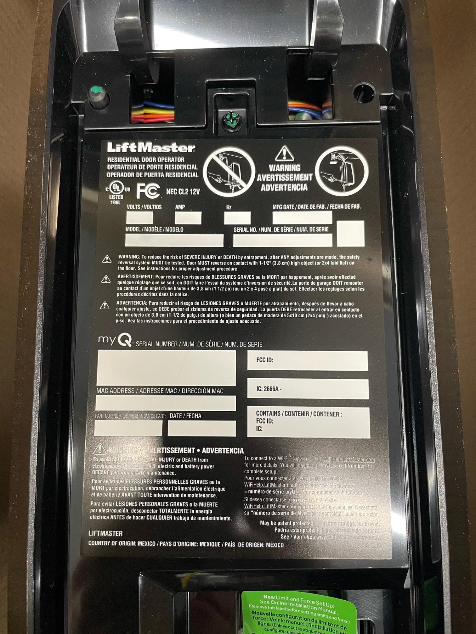
Click to zoom
Application Details
- Equipment Class
- DSS - Part 15 Spread Spectrum Transmitter
- Date of Grant
- Jan 15, 2023
- Application Purpose
- Original Equipment
- Date of Application
- Jan 10, 2023
- Equipment Note
- Wall Mount Garage Door Opener
- Frequency Range
- 902.25000000 - 926.75000000
- Company
- Chamberlain Group LLC, The
- Country
- United States
Documents & Files
Document Text
Text extracted from the exhibit documents filed with the FCC. Open a document above to read the original.
Users Manual
•Please read this manual and the enclosed safety materials carefully! •The door WILL NOT CLOSE unless the Protector System ® is connected and properly aligned. •Periodic checks of the garage door opener are required to ensure safe operation. •The model number is located on the front cover of the opener. •This garage door opener is ONLY compatible with myQ ® , Security+ 2.0 ® , and Security+ 3.0 ® accessories. •Attach warning labels to the location indicated on label. This product is intended for installation only by trained garage door technicians. This product may require adjustments to door springs and/or track configurations. This product is not intended for use on low headroom tracks with outside pick up drums or garage doors utilizing extension springs. For Residential Use Install On Sectional Doors With Torsion Assemblies Only Wall Mount Wi-Fi ® Garage Door Opener Models 93002MC, 93002-VKP1MC LiftMaster 300 Windsor Drive Oak Brook, IL 60523 Register your garage door opener to receive updates and offers from LiftMaster Take a photo of the camera icon including the points (). Send it in by texting the photo to 71403 (US) or visit www.Liftmaster.photo (Global) SM 2 Preparation When you see these Safety Symbols and Signal Words on the following pages, they will alert you to the possibility of serious injury or death if you do not comply with the warnings that accompany them. The hazard may come from something mechanical or from electric shock. Read the warnings carefully. When you see this Signal Word on the following pages, it will alert you to the possibility of damage to your garage door and/or the garage door opener if you do not comply with the cautionary statements that accompany it. Read them carefully. Mechanical Electrical Safety Symbol and Signal Word Review This garage door opener has been designed and tested to offer safe service provided it is installed, operated, maintained and tested in strict accordance with the instructions and warnings contained in this manual. Table of Contents PREPARATION 2 myQ Serial Number ......................................2 Safety Symbol and Signal Word Review ......2 Unattended Operation ...................................2 Planning ........................................................3 Before You Connect with Your Smartphone 4 Preparing Your Garage Door ........................5 Tools Needed ................................................5 Carton Inventory ...........................................6 Additional Items You May Need ...................6 ASSEMBLY 7 Attach the Collar to the Garage Door Opener .....................................7 Attach Mounting Bracket to Garage Door Opener .....................................8 INSTALLATION 8 Position and Mount the Garage Door Opener .....................................9 Attach the Emergency Release Rope and Handle ..................................................10 Install Automatic Door Lock .......................10 Install the Door Control (Smart Control Panel ® ) ...............................12 Install myQ Remote LED Light ...................13 Install the Protector System ......................14 Connect Power ............................................17 Install the Battery Backup ...........................19 ADJUSTMENT 20 Program the Travel .....................................20 Automatic Force Set Up ..............................20 Test the Safety Reversal System ................21 Test the Protector System .........................21 Test Cable Tension Monitor ........................22 Test Automatic Door Lock ..........................22 To Open the Door Manually ........................22 OPERATION 23 Using Your Garage Door Opener ................24 Connect with Your Smartphone .................25 Using the Door Control ...............................26 PROGRAMMING 28 893MAX Remote Control ............................28 Reprogramming myQ Remote LED Light.....................................................29 To Erase the Memory ..................................29 HomeLink ® ..................................................30 MAINTENANCE 31 Care of Your Garage Door Opener ..............31 TROUBLESHOOTING 32 Diagnostic Chart ..........................................32 Additional Troubleshooting .........................33 REPAIR PARTS 35 Installation Parts .........................................35 Garage Door Opener Assembly Parts .........36 CONTACT INFORMATION 36 ACCESSORIES 37 WARRANTY 38 Automatic Garage Door Opener Safety & Maintenance Guide 39 Date of Purchase: Write down the following information for future reference: Product Serial Number: myQ Serial Number: Serial Numbers WARNING: This product can expose you to chemicals including lead, which are known to the State of California to cause cancer or birth defects or other reproductive harm. For more information go to www.P65Warnings.ca.gov. The Timer-to-Close (TTC) feature, the myQ Smartphone Control app, and myQ Garage Door and Gate Monitor are examples of unattended close and are to be used ONLY with sectional doors. Any device or feature that allows the door to close without being in the line of sight of the door is considered unattended close. The Timer-to-Close (TTC) feature, the myQ Smartphone Control, and any other myQ devices are to be used ONLY with sectional doors. myQ Remote LED Light must be installed to enable use of Timer To Close or myQ Smartphone Control of the door. myQ Serial Number Unattended Operation 3 Preparation Survey your area to see if any of the conditions below apply to your installation. Depending on your requirements, additional materials may be required. THIS DOOR OPENER IS COMPATIBLE WITH: • Doors that use a torsion bar and springs. The torsion bar must be 1" (2.5 cm) diameter. NOT compatible with reverse wound drums. • 4-6" (10-15 cm) drums, not to be used on tapered drums over 6" (15 cm). • 3 to 3.9 inch (7.6cm to 9.9cm) drums may be used on doors up to 430lbs. (195.4Kgs) • …
Text truncated - open the document above for the full version.
Users Manual
30 HomeLink ® In the rare case the HomeLink system does not program with the Security+ 2.0 Garage door opener, install a repeater kit. Refer to HomeLink instructions below. HomeLink is the in-vehicle system. The image used is for reference only and your product may look different. WHEN TO INSTALL A HOMELINK REPEATER KIT All 2006 and Older vehicles – A repeater kit is required and must be purchased by the homeowner. All 2007 and Newer vehicles – Program the HomeLink according to the vehicle instructions. If after ONE attempt to program the HomeLink to the garage door opener and you are unsuccessful, install a repeater. HOW TO ORDER Order the HomeLink repeater kit from an installer or call 1-800-355-3515. To program the HomeLink repeater kit, refer to the instructions provided in the kit or visit: http://www.homelink.com/program. INSTALLATION QUICK FACTS • Only one repeater kit is required per home. • Use different HomeLink buttons in vehicle if programming multiple cars, button 1 first car, button 2 second car... etc. • HomeLink remote is NOT a garage door opener. • If you are using the HomeLink repeater with a garage door opener that has a battery backup system, ensure your original garage door opener remote control is programmed to the garage door opener and place it in your glove box for use in the event of a power outage. • The remote included in this repeater kit MUST be kept for future programming (new vehicle, new garage door opener etc). IIIIII HomeLink Repeater Kit Programming 31 Maintenance MAINTENANCE SCHEDULE EVERY MONTH • Manually operate door. If it is unbalanced or binding, call a trained door systems technician. • Check to be sure door opens and closes fully. Adjust limits if necessary (see Adjustment Step 1). • Repeat the safety reversal test. Make any necessary adjustments (see Adjustment Step 2). EVERY YEAR • Oil door rollers, bearings and hinges. The garage door opener does not require additional lubrication. Do not grease the door tracks. EVERY TWO TO THREE YEARS • Use a rag to wipe away the existing grease from the garage door opener rail. Reapply a small layer of white lithium grease to the top and underside of the rail surface where the trolley slides. myQ Remote LED Light • Unplug the light before cleaning. • Use a lightly dampened cloth for cleaning. • DO NOT use liquid cleaners on the light lens. Care of Your Garage Door Opener To prevent possible SERIOUS INJURY or DEATH: • NEVER allow small children near batteries. • If battery is swallowed, immediately notify doctor. To reduce risk of fire, explosion or chemical burn: • Replace ONLY with 3V CR2032 coin batteries. • DO NOT recharge, disassemble, heat above 212° F (100° C) or incinerate. THE REMOTE CONTROL BATTERY The LED(s) on your remote control will stop flashing when the battery is low and needs to be replaced. To replace battery, open the case as shown. Insert battery positive side up (+). Replace the battery with only 3V CR2032 coin cell batteries. Dispose of old battery properly. 3V CR2032 Pry open the case first in the middle (1), then at each side (2 and 3) with the visor clip. 1 2 3 32 Troubleshooting Your garage door opener is programmed with self-diagnostic capabilities. The UP and DOWN arrows on the garage door opener flash the diagnostic codes. Diagnostic Chart Garage Door Opener Diagnostic LED UP Button DOWN Button DIAGNOSTIC CODESYMPTOMSOLUTION Up Arrow Flash(es) Down Arrow Flash(es) 11The garage door opener will not close. Safety sensors are not installed, connected or wires may be cut. Inspect sensor wires for a disconnected or cut wire. 12The garage door opener will not close. There is a short or reversed wire for the safety sensors. Inspect safety sensor wire at all staple points and connection points and replace wire or correct as needed. 13The door control will not function. The wires for the door control are shorted or the door control is faulty. Inspect door control wires at all staple points and connection points and replace wire or correct as needed. 14The garage door opener will not close, and the lights flash. Safety sensors are misaligned or were momentarily obstructed. Realign both sensors to ensure both LEDs are steady and not flickering. Make sure nothing is hanging or mounted on the door that would interrupt the sensors path while closing. 15Door moves 6-8" (15-20 cm) stops or reverses. Manually open and close the door. Check for binding or obstructions, such as a broken spring or door lock, correct as needed. Check wiring connections at travel module and at the logic board. Replace travel module if necessary. No movement, only a single click. Manually open and close the door. Check for binding or obstructions, such as a broken spring or door lock, correct as needed. Replace logic board if necessary. Opener hums for 1-2 seconds no movement. Manually open and close the door. Check for binding or obstructions, such as a broken spring or door lock, correct as needed. Replace motor if necessary. 16Door coast after it has come to a complete stop. Program travel to coasting position or have door balanced by a trained technician. 21-5No movement or sound.Replace logic board. 31The garage door opener moves slightly, then stops Activate the garage door opener again. If problem persists, replace logic board. 33The battery status LED is constantly flashing green. Battery backup charging circuit error, replace logic board. 35The garage door opener will not close or door reverses during travel. If two cable tension monitors were previously installed and one has been removed, unplug and plug in the opener three times to relearn the monitor to the opener. • Check for possible door obstructions and remove. • Check that the cable tension monitor is properly connected to the opener. • Replace the cable tension monitor. • Reset CTM Learn (See page #) to apporpriate to what you installed. 41-4Door is moving, stops or reverses. Opener beeps and lights flash. Manually open and close the door. Check fo…
Text truncated - open the document above for the full version.
Users Manual
17 Onglet de terre Vis de terre verte Fil de terre Fil noir du câble d’alimentation Fil blanc du câble d’alimentation Conduit flexible Connecteur 90 ̊ (Non fourni) Fil vert Fil blanc Fil noir VUE ARRIÈRE Connecter l’alimentation 8 OPTION B : CONNEXION PERMANENTE DU CÂBLAGE Si un câblage permanent est requis par votre code local, consultez la procédure suivante. 1. Pour établir une connexion permanente à travers le trou de 7/8 po à l’arrière de l’ouvre-porte de garage (selon le code local) : 2. Assurez-vous que l’alimentation n’est PAS connectée à l’ouvre-porte et coupez l’alimentation du circuit. 3. Retirez l’ouvre-porte de garage de la barre de torsion, enlevez les vis du couvercle et mettez le couvercle de côté. 4. Coupez le cordon de ligne à 15,2 cm (6 po) au-dessus de la décharge de traction. 5. Serrez la décharge de traction et poussez-la dans l’ouvre-porte de garage, puis retirez la décharge de traction du cordon d’alimentation. 6. Installez un conduit à 90° (non fourni) ou un adaptateur de câble flexible (non fourni) dans le trou de 7/8 po. Réinstallez l’ouvre-porte de garage sur la barre de torsion. 7. Faites passer les fils dans le conduit, coupez-les à la bonne longueur, puis dénudez-les. 8. Dénudez 1,3 cm (1/2 po) d’isolant des fils noir, blanc et vert existants. 9. Connectez la ligne au fil noir et le neutre au fil blanc à l’aide d’écrous (non fournis). Connectez le fil de terre à la vis de terre verte. 10. Fixez correctement les fils sous des attaches en plastique afin qu’ils n’entrent pas en contact avec les pièces mobiles. 11. Réinstallez le couvercle. Pour éviter les difficultés d’installation, assurez-vous de ne pas faire fonctionner l’ouvre-porte à ce moment-là. Pour réduire le risque de choc électrique, votre ouvre-porte de garage est équipé d’une fiche de type mise à la terre avec une troisième goupille de mise à la terre. Cette fiche rentre seulement dans une prise de terre. Si la fiche ne rentre pas dans la prise, communiquez avec un électricien qualifié pour faire installer une prise adéquate. Il existe deux options pour connecter l’alimentation : OPTION A - CÂBLAGE TYPIQUE 1. Branchez l’ouvre-porte de garage dans une prise de courant mise à la terre. 2. Ne faites PAS fonctionner l’ouvre-porte de garage à ce moment-là. Pour éviter les risques de BLESSURES GRAVES voire MORTELLES par électrocution ou incendie : • Assurez-vous que le courant n’est PAS connecté à l’ouvre-porte, et débranchez le courant du circuit AVANT de retirer le couvercle pour établir une connexion permanente. • L’installation et le câblage de la porte de garage DOIVENT être conformes à TOUS les codes électriques et de construction locaux. • N’utilisez JAMAIS de rallonge, d’adaptateur à 2 fils ou ne modifiez en AUCUN cas la fiche pour l’adapter à la prise. Assurez-vous que l’ouvre-porte est mis à la terre. Avertissement Avertissement Avertissement Attention RIGHT WRONG RIGHTWRONG Ground Tab Green Ground Screw Ground Wire Black Wire PERMANENT WIRING CONNECTION White Wire Black Wire Ground Tab Green Ground Screw Ground Wire Black Wire PERMANENT WIRING CONNECTION White Wire Black Wire RIGHT WRONG RIGHTWRONG Ground Tab Green Ground Screw Ground Wire Black Wire PERMANENT WIRING CONNECTION White Wire Black Wire Ground Tab Green Ground Screw Ground Wire Black Wire PERMANENT WIRING CONNECTION White Wire Black Wire INCORRECTCORRECT Installation (SUITE) 18 Alignez les capteurs d’inversion de sécurité La porte ne se fermera pas si les capteurs n’ont pas été installés et alignés correctement. Les DEL des deux capteurs doivent être allumés en permanence, ce qui indique qu’ils sont alimentés et alignés correctement. Le capteur d’envoi (avec une DEL ambre) transmet un faisceau lumineux invisible au capteur de réception (avec une DEL verte). Si un obstacle brise le faisceau lumineux pendant la fermeture de la porte, la porte s’arrête, puis retourne en position complètement ouverte. Si la porte est déjà ouverte, elle ne se ferme pas. POUR ALIGNER LES CAPTEURS : Les capteurs peuvent être alignés en desserrant les écrous à oreilles, alignant les capteurs et resserrant les écrous à oreilles. Si les DEL ne sont pas allumées en continu : Capteur de réception (un autocollant est apposé au dos) DEL verte Capteur d’envoi DEL ambre Si le capteur de réception se trouve en plein soleil, intervertissez-le avec le capteur d’émission de manière à ce qu’il se trouve du côté opposé de la porte. (rayon lumineux invisible) Installation (SUITE) • Vérifiez que les deux capteurs sont installés à l’intérieur du garage, un de chaque côté de la porte. • Vérifiez que les capteurs se font face, que les lentilles sont alignées et que le capteur de réception ne reçoit pas la lumière directe du soleil. • Vérifiez que les capteurs ont la même mesure et qu’ils ne ne sont pas placé à plus de 15 cm (6 po) au-dessus du sol. La DEL ambre n’est pas allumée : • Vérifiez que l’ouvre-porte de garage est bien alimenté. • Vérifiez que le fil du capteur n’est pas court-circuité ou cassé. • Vérifiez que le capteur a été câblé correctement : les fils blancs à la borne blanche et les fils blancs/noirs à la borne grise. La DEL verte n’est pas allumée : • Vérifiez que le fil du capteur n’est pas court-circuité ou cassé. • Vérifiez que les capteurs sont alignés. ASSUREZ-VOUS QUE LE CONTRÔLE DE LA PORTE EST CORRECTEMENT CÂBLÉ La DEL de commande jaune et la DEL d’apprentissage de la commande de porte clignote rapidement pendant 5 minutes au maximum pendant que la commande de porte se recharge. Lorsque la commande de la porte est opérationnelle, la DEL jaune de commande s’allume en permanence. 9 19 Pour réduire les risques d’INCENDIE ou de BLESSURE CORPORELLE : • Débranchez TOUTE l'alimentation électrique et la batterie AVANT d’effectuer TOUT entretien ou toute maintenance. • Utilisez UNIQUEMENT la pièce 485LM de Chamberlain pour remplacer la batterie. • NE jetez PAS la batterie dans un feu. La batterie peut exploser. Vérifiez les codes locaux pour les instructions…
Text truncated - open the document above for the full version.
Cover Letter(s)
Dec 8, 2022 To: Federal Communications Commission Authorization and Evaluation Division 7435 Oakland Mills Road Columbia, MD Subject: Permanent Confidentiality Request for FCC ID: HBW0349 Pursuant to sections 0.457 and 0.459 of CFR 47, we respectfully request permanent confidential treatment of the following Exhibits accompanying this application as: - e.g. Block Diagram - e.g. Schematics & Parts List - e.g. Operational Description The above materials contain trade secrets and proprietary information not customarily released to the public. The public disclosure of these materials may be harmful to the applicant and provide unjustified benefits to its competitors. The applicant understands that disclosure of this application and all accompanying documentation will not be made before the date of the Grant for this application. Sincerely, Barbara Kelkhoff, Regulatory Engineering Manager The Chamberlain Group LLC. Email: [email protected]
Cover Letter(s)
Dec 8, 2022 To: Federal Communications Commission Office of Engineering and Technology Equipment Authorization Division 7345 Oakland Mills Road Columbia, Maryland 21046 Subject: Short Term Confidentiality Request for FCC ID: HBW0349 To Whom It May Concern: Pursuant to sections 0.457 and 0.459 of CFR 47, and to avoid premature release of sensitive information prior to marketing or release of the product to the public, the applicant requests the following documents contained in this certification application be temporarily withheld from public disclosure for an initial period of 45 or 180 days; or for a specified date of / / not to exceed 180 days from the Grant Date. See KDB 726920. - e.g. User Manual - e.g. Internal Photos - e.g. Test Setup photos - e.g. External Photos The above materials contain trade secrets and proprietary information not customarily released to the public. The public disclosure of these materials may be harmful to the applicant and provide unjustified benefits to its competitors. Sincerely, Barbara Kelkhoff, Regulatory Engineering Manager The Chamberlain Group LLC. Email: [email protected]
Cover Letter(s)
Dec 8, 2022 To: Elite Electronic Engineering. 1516 Centre Circle Downers Grove, IL 60515-1082 USA Dear Sir/Madam, Re: Project and Product Certification Representative Authorization Letter We, Chamberlain Group LLC. hereby authorize Elite Electronic Engineering to act as a Certification Body for certifying for the following project(s): FCC ID: HBW0349 Product Description: Wall Mount Garage Door Opener Models: 93002-VKP1, 93002RGD-VKP1, RJO101 & 041DJ003. We affirm that between Elite Electronic Engineering and Chamberlain Group Inc, The, any difference in understanding, including test plan, measurement methods, applicable standards and relevant procedures and processes have been resolved prior to commencement of testing activities. Sincerely, Barbara Kelkhoff, Regulatory Engineering Manager The Chamberlain Group LLC Email: [email protected]
Cover Letter(s)
Date: Dec 8, 2022 Page 1 of 1 The Chamberlain Group LLC 300 Windsor Dr Oak Brook, IL 60523 To: Federal Communication Commission Equipment Authorization Division Application Processing Branch 7435 Oakland Mills Rd Columbia, MD 21046 New FCC ID: HBW0349; IC 2666A-0349 for our Main Control/transceiver for use in Wall Mount Garage Door Opener To whom it may concern, We would like to submit for Certification to FCC a new FCC ID: HBW0349 for our Main Control/transceiver for use in Wall Mount Garage Door Opener. Product Description: Wall Mount Garage Door Opener Models: 93002-VKP1, 93002RGD-VKP1, RJO101. Please find in the following application all related documentation to support this new certification. We would appreciate your prompt attention to the submittal. If there are any questions, please contact me by phone, fax or email. Sincerely, Barbara Kelkhoff Regulatory Engineering Manager Chamberlain Group Tel: 630.993.6306 Fax: 630.516.6863 Email: [email protected]
ID Label/Location Info
0349 HBW0349 041DJ003 MC 93002-VKP1 MC 01/05/2023 120 601.5 01/05/2023
RF Exposure Info
1516 Centre Circle, Downers Grove IL 60515 RF EXPOSURE EXHIBIT Manufacturer Name The Chamberlain Group LLC Manufacturer Address 300 Windsor Drive Oak Brook,IL 60523 Model No. Residential Jackshaft Opener HVIN 041DJ003 Specifications FCC “Code of Federal Regulations” Title 47 Part 1.1307(b) FCC “Code of Federal Regulations” Title 47 Part 2.1093 Industry Canada RSS-102 Test Facility Elite Electronic Engineering, Inc. 1516 Centre Circle, Downers Grove, IL 60515 FCC Reg. Number: 269750 IC Reg. Number: 2987A CAB Identifier: US0107 Test Procedure FCC KDB 447498 D01 General RF Exposure Guidance v06 RSS-102, Issue 5 Radio Frequency (RF) Exposure Compliance of Radiocommunication Apparatus (All Frequency Bands ANSI/IEEE C95.1-1992, "Safety Levels with Respect to Human Exposure to Radio Frequency Electromagnetic Fields, 3 kHz to 300 GHz," Evaluation Distance 20 cm Radio Access Technology ƒ Transmit Frequency (MHz) ERP/P (dBm) ERP/P (mW) WIFI 2412 24.9 309.0295433 BLE 2402 1.5 1.412537545 security 2402 9 7.943282347 900MHz 914 17.56 57.01642723 Equipment is exempt from routine evaluation Radio Access Technology ƒ Transmit Frequency (MHz) ERP/P (mW) Power Threshold (mW) Calculated Power Density (mW/cm 2 ) Power Density Limit (mW/cm 2 ) Fractional Contributions ∑ Fractional Contributions WIFI2412------0.0614794741.000.06150.082 BLE2402------0.0002810151.000.0003 security2402------0.0015802661.000.0016 900MHz914------0.0113430580.610.0186 1516 Centre Circle, Downers Grove IL 60515 Radio Access Technology ƒ Transmit Frequency (MHz) S C Calculated Power Density (W/m 2 ) S L Power Density Limit (W/m 2 ) S C :S L Ratio ∑ S C :S L Ratio WIFI24120.6147946815.3660182780.1145718570.16 BLE24020.0028101545.3508045630.000525183 security24020.0158026575.3508045630.002953323 900MHz9140.1134305672.7646880070.041028343 Assessment Results Relevant to General/Uncontrolled Exposure Limits
Test Report
Engineering Test Report No. 2202429-03 Page 83 of 102 Test Setup for Spurious Radiated Emissions, 30MHz – 1GHz – Antenna Polarization Horizontal Test Setup for Spurious Radiated Emissions, 30MHz – 1GHz – Antenna Polarization Vertical Engineering Test Report No. 2202429-03 Page 84 of 102 Test Setup for Spurious Radiated Emissions, Above 1GHz – Antenna Polarization Horizontal Test Setup for Spurious Radiated Emissions, Above 1GHz – Antenna Polarization Vertical Engineering Test Report No. 2202429-03 Page 85 of 102 Test Details Manufacturer Chamberlain Group, LLC. EUT Residential Jackshaft Opener Model No. RJOA MPP Serial No. Radiated Sample 2 Test Peak Measurements in the Restricted Bands Mode Transmit at 902.25MHz Date Tested December 2, 2022 through December 5, 2022 Notes Meter CBL Ant Pre Total Total Limit Freq. Ant Reading Fac Fac Amp dBuV/m uV/m uV/m Margin MHz Pol (dBuV) Ambient (dB) (dB/m) (dB) at 3m at 3 m at 3 m (dB) 2706.75 H 57.0 2.8 33.4 -40.2 53.0 448.0 5000.0 -21.0 2706.75 V 55.7 2.8 33.4 -40.2 51.7 385.7 5000.0 -22.3 3609.00 H 62.5 3.2 34.6 -39.5 60.8 1098.8 5000.0 -13.2 3609.00 V 59.4 3.2 34.6 -39.5 57.7 769.0 5000.0 -16.3 4511.25 H 51.7 3.6 35.9 -39.6 51.6 380.5 5000.0 -22.4 4511.25 V 51.2 3.6 35.9 -39.6 51.1 359.2 5000.0 -22.9 5413.50 H 53.9 3.9 36.6 -39.5 54.9 556.8 5000.0 -19.1 5413.50 V 53.1 3.9 36.6 -39.5 54.1 507.8 5000.0 -19.9 8120.25 H 48.8 Ambient 4.9 38.3 -39.6 52.4 417.6 5000.0 -21.6 8120.25 V 48.8 Ambient 4.9 38.3 -39.6 52.4 417.6 5000.0 -21.6 9022.50 H 47.8 Ambient 4.9 38.6 -39.4 52.0 396.3 5000.0 -22.0 9022.50 V 48.0 Ambient 4.9 38.6 -39.4 52.2 405.5 5000.0 -21.8 Engineering Test Report No. 2202429-03 Page 86 of 102 Test Details Manufacturer Chamberlain Group, LLC. EUT Residential Jackshaft Opener Model No. RJOA MPP Serial No. Radiated Sample 2 Test Average Measurements in the Restricted Bands Mode Transmit at 902.25MHz Date Tested December 2, 2022 through December 5, 2022 Notes Average Average Average Meter CBL Ant Pre Duty Total Total Limit Freq. Ant Reading Fac Fac Amp Cycle dBuV/m uV/m uV/m Margin MHz Pol (dBuV) Ambient (dB) (dB/m) (dB) (dB) at 3m at 3 m at 3 m (dB) 2706.75 H 57.00 2.8 33.4 -40.2 -37.9 15.2 5.7 500.0 -38.8 2706.75 V 55.7 2.8 33.4 -40.2 -37.9 13.9 4.9 500.0 -40.1 3609.00 H 62.5 3.2 34.6 -39.5 -37.9 22.9 14.0 500.0 -31.0 3609.00 V 59.4 3.2 34.6 -39.5 -37.9 19.8 9.8 500.0 -34.1 4511.25 H 51.7 3.6 35.9 -39.6 -37.9 13.7 4.9 500.0 -40.2 4511.25 V 51.2 3.6 35.9 -39.6 -37.9 13.2 4.6 500.0 -40.7 5413.50 H 53.9 3.9 36.6 -39.5 -37.9 17.0 7.1 500.0 -36.9 5413.50 V 53.1 3.9 36.6 -39.5 -37.9 16.2 6.5 500.0 -37.7 8120.25 H 4.9 38.3 -39.6 -37.9 -34.3 0.0 500.0 -88.2 8120.25 V 48.8 Ambient 4.9 38.3 -39.6 -37.9 14.5 5.3 500.0 -39.4 9022.50 H 47.8 Ambient 4.9 38.6 -39.4 -37.9 14.1 5.1 500.0 -39.9 9022.50 V 48.0 Ambient 4.9 38.6 -39.4 -37.9 14.3 5.2 500.0 -39.7 Engineering Test Report No. 2202429-03 Page 87 of 102 Test Details Manufacturer Chamberlain Group, LLC. EUT Residential Jackshaft Opener Model No. RJOA MPP Serial No. Radiated Sample 2 Test Peak Measurements in the Non-Restricted Bands Mode Transmit at 902.25MHz Date Tested December 2, 2022 through December 5, 2022 Notes Peak Peak Peak Meter CBL Ant Pre Total Total Limit Freq. Ant Reading Fac Fac Amp dBuV/m uV/m uV/m Margin MHz Pol (dBuV) Ambient (dB) (dB/m) (dB) at 3m at 3 m at 3 m (dB) 902.25 H 84.4 1.5 26.5 0.0 112.4 418018.7 NA NA 902.25 V 82.1 1.5 26.5 0.0 110.1 320771.5 NA NA 1804.50 H 70.6 2.2 31.5 -40.1 64.2 1622.2 41801.9 -28.2 1804.50 V 71.9 2.2 31.5 -40.1 65.5 1884.1 41801.9 -26.9 6315.75 H 60.3 4.3 38.1 -39.6 63.1 1431.4 41801.9 -29.3 6315.75 V 59.6 4.3 38.1 -39.6 62.4 1320.5 41801.9 -30.0 7218.00 H 52.8 4.6 38.4 -39.7 56.2 644.0 41801.9 -36.2 7218.00 V 45.9 4.6 38.4 -39.7 49.3 291.0 41801.9 -43.1 Engineering Test Report No. 2202429-03 Page 88 of 102 Test Details Manufacturer Chamberlain Group, LLC. EUT Residential Jackshaft Opener Model No. RJOA MPP Serial No. Radiated Sample 2 Test Peak Measurements in the Restricted Bands Mode Transmit at 914.75MHz Date Tested December 2, 2022 through December 5, 2022 Notes Peak Peak Peak Meter CBL Ant Pre Total Total Limit Freq. Ant Reading Fac Fac Amp dBuV/m uV/m uV/m Margin MHz Pol (dBuV) Ambient (dB) (dB/m) (dB) at 3m at 3 m at 3 m (dB) 2744.25 H 56.3 2.8 33.2 -40.2 52.1 404.7 5000.0 -21.8 2744.25 V 53.7 2.8 33.2 -40.2 49.5 300.0 5000.0 -24.4 3659.00 H 61.6 3.3 34.8 -39.5 60.1 1013.0 5000.0 -13.9 3659.00 V 60.9 3.3 34.8 -39.5 59.4 934.6 5000.0 -14.6 4573.75 H 49.6 Ambient 3.6 36.4 -39.7 49.9 311.6 5000.0 -24.1 4573.75 V 49.6 Ambient 3.6 36.4 -39.7 49.9 311.6 5000.0 -24.1 7318.00 H 51.2 4.7 38.2 -39.6 54.4 527.8 5000.0 -19.5 7318.00 V 49.1 Ambient 4.7 38.2 -39.6 52.3 414.5 5000.0 -21.6 8232.75 H 48.4 Ambient 4.9 38.4 -39.5 52.2 407.4 5000.0 -21.8 8232.75 V 48.0 Ambient 4.9 38.4 -39.5 51.8 389.0 5000.0 -22.2 9147.50 H 48.4 Ambient 5.0 38.7 -39.4 52.7 433.1 5000.0 -21.2 9147.50 V 48.3 Ambient 5.0 38.7 -39.4 52.6 428.2 5000.0 -21.3 Engineering Test Report No. 2202429-03 Page 89 of 102 Test Details Manufacturer Chamberlain Group, LLC. EUT Residential Jackshaft Opener Model No. RJOA MPP Serial No. Radiated Sample 2 Test Average Measurements in the Restricted Bands Mode Transmit at 914.75MHz Date Tested December 2, 2022 through December 5, 2022 Notes Average Average Average Meter CBL Ant Pre Duty Total Total Limit Freq. Ant Reading Fac Fac Amp Cycle dBuV/m uV/m uV/m Margin MHz Pol (dBuV) Ambient (dB) (dB/m) (dB) (dB) at 3m at 3 m at 3 m (dB) 2744.25 H 56.30 2.8 33.2 -40.2 -37.9 14.3 5.2 500.0 -39.7 2744.25 V 53.7 2.8 33.2 -40.2 -37.9 11.7 3.8 500.0 -42.3 3659.00 H 61.6 3.3 34.8 -39.5 -37.9 22.2 12.9 500.0 -31.7 3659.00 V 60.9 3.3 34.8 -39.5 -37.9 21.5 11.9 500.0 -32.4 4573.75 H 49.6 Ambient 3.6 36.4 -39.7 -37.9 12.0 4.0 500.0 -42.0 4573.75 V 3.6 36.4 -39.7 -37.9 -37.6 0.0 500.0 -91.6 7318.00 H 51.2 4.7 38.2 -39.6 -37.9 16.6 6.7 500.0 -37.4 7318.00 V 49.1 Ambient 4.7 38.2 -39.6 -37.9 14.5 5.3 500.0 -39.5 8232.75 H 48.4 Ambient 4.9 38.4 -39.5 -37.9 14.3 5.2 …
Text truncated - open the document above for the full version.
Test Report
Engineering Test Report No. 2202429-06 Report Date December 15, 2022 Manufacturer Name Chamberlain Grou…
Text truncated - open the document above for the full version.
Contact Information
Applicant
Thomas DeSilvia(Director Corporate Compliance)
Technical Contact
The Chamberlain Group, Inc.Lin Liu
[email protected]6309936541
300 Windsor Drive · Oak Brook · United States
Test Firm
Elite Electronic Engineering Inc.Kevin Halpin
Technical Specifications
| # | Rule Parts | Frequency Range | Power Output |
|---|---|---|---|
| 1 | 15C | 902.25 MHz - 926.75 MHz | 33.10 mW |
Other Applications from Chamberlain Group LLC, The

HBW73514
Jul 06, 2026iDock Link 2
Equipment Class
DSS - Part 15 Spread Spectrum TransmitterHBW-VKP2K
Jun 23, 2026SMART GARAGE VIDEO KEYPAD
Equipment Class
DTS - Digital Transmission System
HBWCHM1
Dec 03, 2025Wireless Chime
Equipment Class
DTS - Digital Transmission SystemHBWN519
Oct 10, 2024VEHICULAR GATE OPENER
Equipment Class
DSS - Part 15 Spread Spectrum TransmitterHBWN329
Sep 22, 2024Handheld Remote
Equipment Class
DSC - Part 15 Security/Remote Control Transmitter