HBW0716-1Single Button Programmable DIP Remote Control Transmitter
Chamberlain Group LLC, The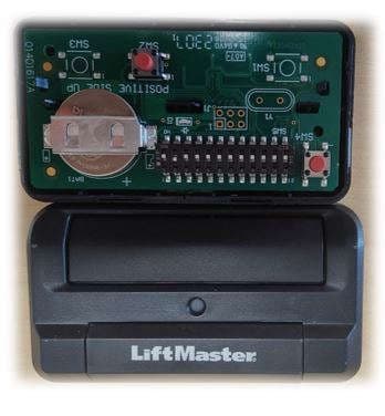
Click to zoom
Application Details
- Equipment Class
- DSC - Part 15 Security/Remote Control Transmitter
- Date of Grant
- Dec 04, 2023
- Application Purpose
- Original Equipment
- Date of Application
- Nov 29, 2023
- Equipment Note
- Single Button Programmable DIP Remote Control Transmitter
- Frequency Range
- 390.00000000 - 390.00000000
- Company
- Chamberlain Group LLC, The
- Country
- United States
Documents & Files
Document Text
Text extracted from the exhibit documents filed with the FCC. Open a document above to read the original.
Users Manual
Introduction The 811LMX and 813LMX are programmable DIP switch remote controls for use with LiftMaster commercial products using Security+ 2.0 ® Encrypted DIP, as well as older 315 MHz DIP and 390 MHz DIP devices. The remote control default setting is Security+ 2.0 ® . The 813LMX model is designed for OPEN/ CLOSE/STOP functionality. The images throughout this manual are for reference only and your product may look different. 1 Slide the cover open to access the DIP switches. 2 Use a pen or screwdriver to slide the DIP switches to any position you want (ON or OFF). 811LMX813LMX WARNING: This product can expose you to chemicals including lead, which are known to the State of California to cause cancer or birth defects or other reproductive harm. For more information go to www.P65Warnings.ca.gov. To prevent possible serious injury or death from a moving gate or garage door: • ALWAYS keep remote controls out of reach of children. NEVER permit children to operate, or play with remote control transmitters. • Activate gate or door ONLY when it can be seen clearly, is properly adjusted, and there are no obstructions to door travel. • ALWAYS keep gate or garage door in sight until completely closed. Never permit anyone to cross path of moving gate or door. PROGRAMMABLE DIP SWITCH REMOTE CONTROLS Models 811LMX and 813LMX Programming Step 1: Set the DIP Switches Cover DIP Switch Yellow LED Follow these steps to select 315 MHz DIP, 390 MHz DIP or to reset the remote to Security+ 2.0 ® Encrypted DIP from a different setting. 1 Locate and press the Program Button. The LED glows steady Yellow. Step 2: Select the Security Type NOTE: If the device you use with this remote is Security+ 2.0 ® Encyrpted DIP, skip this step and go to Step 3: Program the Remote to a Device. 2 Press any remote control button the number of times that corresponds to the security type for your device. 3 Press and hold the Program Button until the LED on the front of the remote turns off. Program Button # OF PRESSESDEVICE SECURITY TYPE 1Security+ 2.0 ® 2315 MHz DIP 3390 MHz DIP The Remote Control Battery To prevent possible SERIOUS INJURY or DEATH: • NEVER allow small children near batteries. • If battery is swallowed, immediately notify doctor. To reduce risk of fire, explosion or chemical burn: • Replace ONLY with 3V CR2032 coin batteries. • DO NOT recharge, disassemble, heat above 212°F (100°C) or incinerate. The lithium battery should produce power for up to 3 years. To replace battery: Replacement Parts Visor Clip . . . . . . . . . . . . . . . . . . . . . . . . . . . . . . . . . . . . . . . . . . . . . . . . . . . . . . . . . . . . . . . . . . K029B0137 3V CR2032 lithium Battery . . . . . . . . . . . . . . . . . . . . . . . . . . . . . . . . . . . . . . . . . . . . . . . . . . . . K010A0020 NOTICE: To comply with FCC and/or Industry Canada (IC) rules, adjustment or modifications of this transceiver are prohibited. THERE ARE NO USER SERVICEABLE PARTS. This device complies with Part 15 of the FCC rules and IC RSS-210. Operation is subject to the following two conditions: (1) this device may not cause harmful interference, and (2) this device must accept any interference received, including interference that may cause undesired operation. Remote 811LMX or (IFT#: _____________) Operation of this equipment is subject to the following two conditions: (1) This equipment may not cause harmful interference, including that which may cause undesired operation. Learn Buttons Example: Your receiver or operator may look different. See your LiftMaster device’s manual for programming. 1 Press and release the LEARN button on your device. 2 Within 30 seconds press and hold the button on the remote control that you wish to program to the device. 3 Test by pressing the remote button you just programmed. The operator or gate activates. Additional buttons on the 813LMX can be programmed to operate other devices of the same security type. The 813LMX can be programmed for OPEN/ CLOSE/STOP functionality. Refer to your device manual for instructions. Step 3: Program the Remote to a Device Open, Close, Stop Introduction Les modèles 811LMX et 813LMX sont des télécommandes à commutateur DIP programmables à utiliser avec les produits commerciaux LiftMaster avec commutateur DIP chiffré Security+ 2.0 ® de même que les dispositifs plus anciens à commutateur DIP de 315 Mhz et 390 MHz. Le réglage par défaut de la télécommande est Security+ 2.0 ® . Le modèle 813LMX est conçu pour la fonctionnalité d’ouverture/fermeture/arrêt. Les illustrations de ce manuel ne sont fournies qu’à titre de référence; votre produit peut avoir une apparence différente. 1 Glisser le couvercle pour l’ouvrir et accéder aux COMMUTATEURS DIP. 2 Utiliser un crayon ou un tournevis pour glisser les DIP commutateurs à la position désirée (ON ou OFF). 811LMX813LMX Pour prévenir d’éventuelles BLESSURES GRAVES ou MORTELLES dues à une barrière ou une porte en mouvement : • Garder TOUJOURS la télécommande hors portée des enfants. Ne JAMAIS permettre à un enfant de faire fonctionner des télécommandes ou de jouer avec celles-ci. • Actionner la porte UNIQUEMENT lorsqu’on la voit clairement, qu’elle est bien réglée et que rien ne gêne sa course. • Garder TOUJOURS la barrière ou la porte en vue jusqu’à sa fermeture complète. Ne JAMAIS permettre à quiconque de passer lorsqu’une barrière ou une porte est en mouvement. COMMUTATEUR DIP RPGORAMMABLE TÉLÉCOMMANDES Modèles 811LMX et 813LMX Programmation Étape 1 : Régler les commutateurs DIP. Couvercle Commutateur DIP DEL jaune Suivre ces étapes pour sélectionner DIP 315 MHz, DIP 390 MHz ou pour réinitialiser la télécommande à un commutateur DIP chiffré Security+ 2.0 ® d’un autre réglage. 1 Repérer et appuyer sur le bouton de programmation. La DEL s’allume en jaune. Étape 2 : Sélectionner le type de sécurité. REMARQUE : Si le dispositif utilisé avec cette télécommande est un commutateur DIP Security+ 2.0 ® chiffré, sauter cette étape et passer à l’étape 3 : P…
Text truncated - open the document above for the full version.
Attestation Statements
TO: Federal Communication Commission Equipment Authorization Division Application Processing Branch 7435 Oakland Mills Rd Columbia, MD 21046 Date: July 10, 2023 Pursuant to FCC 22-84 Report and Order and KDB 986446 D01 Covered Equipment v01, the Commission adopted new FCC requirements to protect the nation’s networks and supply chains from equipment that poses an unacceptable risk to national security or the safety of U.S. persons. Specifically, the Commission adopted rules that prohibit equipment authorization for “covered” telecommunications equipment and video surveillance equipment produced by entities identified on the Commission’s Covered List. Certifications concerning “covered” equipment. Section 2.911(d)(5)(i)-(ii). FCC ID’s: HBW0690, HBW0690-2, HBW0718, HBW0716-1, HBW0716-2 The Chamberlain Group LLC (“the applicant”) certifies that the equipment for which authorization is sought is not “covered” equipment prohibited from receiving an equipment authorization pursuant to section 2.903 of the FCC rules. The Chamberlain Group LLC (“the applicant”) certifies that as of the date of the filing of the application, the applicant is not identified on the covered list as an entity producing covered equipment. Thank you. Regards, Signature: Thomas DeSilvia Date: July 10, 2023 Signed by: Thomas DeSilvia
Attestation Statements
TO: Federal Communication Commission Equipment Authorization Division Application Processing Branch 7435 Oakland Mills Rd Columbia, MD 21046 Date: July 10, 2023 Pursuant to FCC 22-84 Report and Order and KDB 986446 D01 Covered Equipment v01, the Commission adopted new FCC requirements to protect the nation’s networks and supply chains from equipment that poses an unacceptable risk to national security or the safety of U.S. persons. Specifically, the Commission adopted rules that prohibit equipment authorization for “covered” telecommunications equipment and video surveillance equipment produced by entities identified on the Commission’s Covered List. Certification designating a U.S. agent for service of process. As required by section 2.911(d)(7), the applicant must designate a contact located in the United States for purposes of acting as the applicant’s agent for service of process, regardless of whether the applicant is a domestic or foreign entity. An applicant located in the United States may designate itself as the agent for service of process. The Chamberlain Group LLC (“the applicant”) consent to accept the service of process. Contact Name: Tom DeSilvia, Director Corporate Compliance Address: 300 Windsor Drive Oak Brook, IL. 60523 Telephone No: 1-630-993-8618 Email: [email protected] FRN: 004301545 Regards, Signature: Thomas DeSilvia Date: July 10, 2023 Signed by: Thomas DeSilvia This Agreement is valid until rescinded by the Applicant
Cover Letter(s)
July 10, 2023 To: Federal Communication Commission Equipment Authorization Division Application Processing Branch 7435 Oakland Mills Rd Columbia, MD 21046 & Industry Canada Certification and Engineering Bureau P.O. Box 11490, Station H 3701 Carling Avenue (Building 94) Ottawa, Ontario K2H 8S2 Subject: Permanent Confidentiality Request for FCC ID HBW0716-1 and IC ID 2666A-07161 Pursuant to FCC 47 CRF 0.457(d) and 0.459 and IC RSP-100, Section 10, the applicant requests that a part of the subject FCC application be held confidential. We hereby request confidential treatment of information accompanying this application as outlined below: - e.g. block diagrams - e.g. operational description - e.g. schematic diagrams - e.g. BOM / Parts List The above materials contain trade secrets and proprietary information not customarily released to the public. The public disclosure of these materials may be harmful to the applicant and provide unjustified benefits to its competitors. Sincerely, Tom DeSilvia Tom DeSilvia Director Corporate Compliance Chamberlain Group Tel: 630.993.8618 Email: [email protected]
Cover Letter(s)
Date: July 10, 2023 Page 1 of 1 The Chamberlain Group LLC 300 Windsor Dr Oak Brook, IL 60523 To: Federal Communication Commission Equipment Authorization Division Application Processing Branch 7435 Oakland Mills Rd Columbia, MD 21046 New FCC ID: HBW0716-1 for our Single Button Programmable DIP Remote Control Transmitter To whom it may concern, We would like to submit for a new FCC ID (HBW0716-1) for our Single Button Programmable DIP Remote Control Transmitter Product Description: Single Button Programmable DIP Remote Control Transmitter Circuit Assembly: 003-0716-1 Please find in the following application all related documentation to support this new certification. We would appreciate your prompt attention to the submittal. If there are any questions, please contact me by phone, fax, or email. Sincerely, Tom DeSilvia Tom DeSilvia Director Corporate Compliance Chamberlain Group Tel: 630.993.8618 Fax: 630.516.6863 Email: [email protected]
RF Exposure Info
1516 Centre Circle, Downers Grove IL 60515 RF EXPOSURE EXHIBIT Manufacturer Name The Chamberlain Group, Inc. Manufacturer Address 300 Windsor Dr. Oak Brook, IL 60523 Model No. HVIN Specifications FCC “Code of Federal Regulations” Title 47 Part 1.1307(b) FCC “Code of Federal Regulations” Title 47 Part 2.1093 Industry Canada RSS-102 Test Facility Elite Electronic Engineering, Inc. 1516 Centre Circle, Downers Grove, IL 60515 FCC Reg. Number: 269750 IC Reg. Number: 2987A CAB Identifier: US0107 Test Procedure FCC KDB 447498 D01 General RF Exposure Guidance v06 RSS-102, Issue 5 Radio Frequency (RF) Exposure Compliance of Radiocommunication Apparatus (All Frequency Bands ANSI/IEEE C95.1-1992, "Safety Levels with Respect to Human Exposure to Radio Frequency Electromagnetic Fields, 3 kHz to 300 GHz," Evaluation Distance 0 cm Exemption Option A Radio Type ƒ Mid-Band of Transmit Frequency (MHz) Electric Field Strength (E) (dBμV/m) Field Strength Measurement Distance (d) (m) Max Power EIRP (dBm) Max Power EIRP (mW) (Part 1.1307 Option A P th (mW) Periodic Transmitter 3 1 EIRP = E + 20log d – 104.8, where d is the measurement distance 813LMX MC 315 811LMXMC 72.9-22.4.006
Test Report
Engineering Test Report No. 2300430-01 Report Date 10/18/2023 Manufacturer Name Chamberlain Group Inc Manufacturer Address 300 Windsor Dr Oak Brook, IL 60523 Model No. 811LMX MC and 813LMX MC Date Received 9/25/2023 Test Dates 9/25/2023 through 10/18/2023 Specifications FCC "Code of Federal Regulations" Title 47 Part 15, Subpart C, Section 15.231(b) Innovation, Science, and Economic Development Canada, RSS-210 Innovation, Science, and Economic Development Canada, RSS-GEN Test Facility Elite Electronic Engineering, Inc. 1516 Centre Circle, Downers Grove, IL 60515 FCC Reg. Number: 269750 IC Reg. Number: 2987A CAB Identifier: US0107 Signature Tested by Javier Cardenas Signature Approved by Raymond J. Klouda, Registered Professional Engineer of Illinois – 44894 PO Number 4900089862 This report is for your exclusive use. Any copying or replication of this report to or for any other person or entity, or use of our name or trademark, is permitted only with our prior written permission. This report sets forth our findings solely with respect to the test samples identified herein. The results set forth in this report are not indicative or representative of the quality or characteristics of the lot from which a test sample was taken or any similar or identical product unless specifically and expressly noted. Our report includes all of the tests requested by you and the results thereof based upon the information that you provided to us. You have 60 days from date of issuance of this report to notify us of any material error or omission caused by our negligence, provided, however, that such notice shall be in writing and shall specifically address the issue you wish to raise. A failure to raise such issue within the prescribed time shall constitute your unqualified acceptance of the completeness of this report, the tests conducted and the correctness of the report contents. This report shall not be reproduced, except in full, without the written approval of Elite Electronic Engineering Inc. Elite Electronic Engineering Incorporated certifies that the information contained in this report was obtained under conditions which meet or exceed those specified in the FCC "Code of Federal Regulations" Title 47 Part 15, Subpart C, Section 15.231 and Innovation, Science, and Economic Development Canada, RSS-210 and RSS-Gen test specification(s). The data presented in this test report pertains to the EUT on the test date(s) specified. Any electrical or mechanical modifications made to the EUT subsequent to the specified test date will serve to invalidate the data and void this certification. This report must not be used to claim product certification, approval, or endorsement by A2LA, NIST, or any agency of the Federal Government. Engineering Test Report No. 2300430-01 This report shall not be reproduced, except in full, without the written approval of Elite Electronic Engineering Inc. Page 2 of 55 Table of Contents 1. Report Revision History ............................................................................................................................ 3 2. Introduction ............................................................................................................................................... 4 2.1. Scope of Tests .......................................................................................................................................... 4 2.2. Purpose ..................................................................................................................................................... 4 2.3. Identification of the EUT ............................................................................................................................ 4 3. Power Input ............................................................................................................................................... 5 4. Grounding ................................................................................................................................................. 5 5. Support Equipment ................................................................................................................................... 5 6. Interconnect Leads .................................................................................................................................... 5 7. Modifications Made to the EUT ................................................................................................................. 5 8. Modes of Operation ................................................................................................................................... 5 9. Test Specifications .................................................................................................................................... 5 10. Test Plan ................................................................................................................................................... 5 11. Deviation, Additions to, or Exclusions from Test Specifications ............................................................... 5 12. Laboratory Conditions ............................................................................................................................... 6 13. Summary ................................................................................................................................................... 6 14. Sample Calculations ................................................................................................................................. 6 15. Statement of Conformity ........................................................................................................................... 7 16. Certification ............................................................................................................................................... 7 17. Photographs of EUT ............................................…
Text truncated - open the document above for the full version.
Test Report
| Name Universal Visor Antenna Type PCB antenna PCB/ASSY 014R1611/003-0690 Approximate maximum gain -20dB Work Frequencies LATAM 310 Mhz,315 Mhz,390Mhz USA/CANADA 315Mhz,390Mhz Approximate Antenna Dimension Large:49.505mm High: 34.417mm | Name UNIVERSAL CLICKER Antenna Type PCB antenna PCB/ASSY 014R1618/003-0718 Approximate maximum gain -20dB Work Frequencies NORTH AMERICA 303MHz, 310MHz, 315Mhz, 318MHz, 372.5MHz, 390Mhz Approximate Antenna Dimension Large:37mm High: 27.5mm | Name SSU EVOLUTION DIP Antenna Type PCB antenna PCB/ASSY 014R1617/003-0226 Approximate maximum gain -20dB USA/CANADA 315Mhz,390Mhz Approximate Antenna Dimension Large:71.644mm High: 35.634mm
Test Setup Photos
Engineering Test Report No. 2300430-01 Page 31 of 55 Test Setup for Spurious Radiated Emissions, 30-1000MHz – Antenna Polarization Horizontal Test Setup for Spurious Radiated Emissions, 30-1000MHz – Antenna Polarization Vertical Engineering Test Report No. 2300430-01 Page 32 of 55 Test Setup for Spurious Radiated Emissions, Above 1GHz – Antenna Polarization Horizontal Test Setup for Spurious Radiated Emissions, Above 1GHz – Antenna Polarization Vertical
Contact Information
Applicant
Thomas DeSilvia(Director Corporate Compliance)
Technical Contact
The Chamberlain Group, Inc.Thomas Cabaj
6305012269
300 Windsor Drive · Oak Brook · United States
Test Firm
Elite Electronic Engineering Inc.Kevin Halpin
Technical Specifications
| # | Rule Parts | Frequency Range | Power Output |
|---|---|---|---|
| 2 | 15.231 | 390 MHz - 390 MHz | - |
Other Applications from Chamberlain Group LLC, The

HBW73514
Jul 06, 2026iDock Link 2
Equipment Class
DSS - Part 15 Spread Spectrum TransmitterHBW-VKP2K
Jun 23, 2026SMART GARAGE VIDEO KEYPAD
Equipment Class
DTS - Digital Transmission System
HBWCHM1
Dec 03, 2025Wireless Chime
Equipment Class
DTS - Digital Transmission SystemHBWN519
Oct 10, 2024VEHICULAR GATE OPENER
Equipment Class
DSS - Part 15 Spread Spectrum TransmitterHBWN329
Sep 22, 2024Handheld Remote
Equipment Class
DSC - Part 15 Security/Remote Control Transmitter