HBW1255433Remote control transmitter
Chamberlain Group LLC, The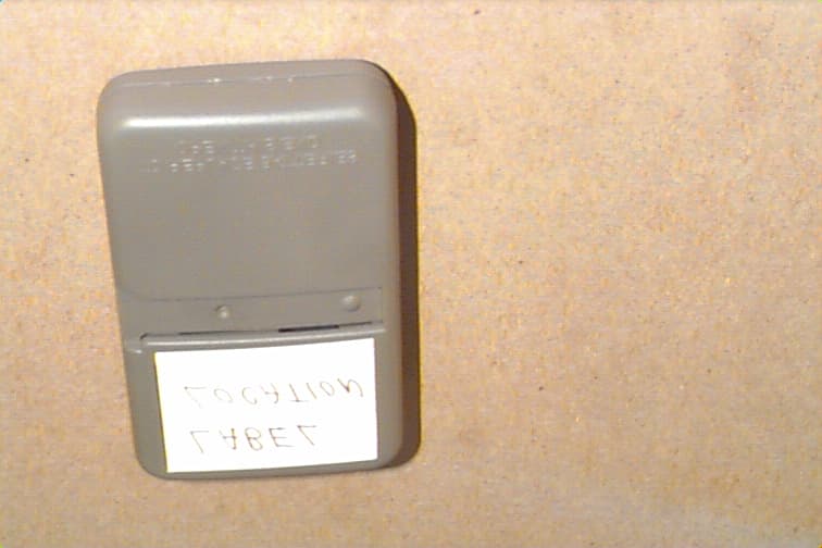
Click to zoom
Application Details
- Equipment Class
- DSC - Part 15 Security/Remote Control Transmitter
- Date of Grant
- Oct 04, 1998
- Application Purpose
- Original Equipment
- Date of Application
- Aug 20, 1998
- Equipment Note
- Remote control transmitter
- Frequency Range
- 433.00000000 - 433.00000000
- Company
- Chamberlain Group LLC, The
- Country
- United States
Documents & Files
Document Text
Text extracted from the exhibit documents filed with the FCC. Open a document above to read the original.
Users Manual
The Security:remote control (with blue push buttons) works only with rolling code door openers and light controls (with an orange SRT button and yellow indicator light). The code between the remote control and the receiver changes with each use, randomly accessing over 100 billion new codes. Instructions are given below for programming your opener to match the remote control's code. The additional remote control buttons can also activate other Security:garage door openers and/or light controls. (Instructions for programming light products are included with those accessories.) ® 433MHz 3-Function Remote Control To comply with FCC rules, adjustment or modifications of this receiver and/or transmitter are prohibited, except for changing the code setting or replacing the battery. THERE ARE NO OTHER USER SERVICEABLE PARTS. SECURITY:GARAGE DOOR OPENERS Program the Opener to Accept the Remote Control Code Select a remote control push button to operate the receiver. The large button is recommended for use with the garage door opener. If you have a Premium Control Console: 1.With the door closed, press and hold the selected remote push button. See Figure 1. 2. Press and hold the Light button on the door control, Figure 2. 3. Press and hold the door control push button. 4. After the opener light flashes, release all buttons. If you do not have a Premium Control Console: 1. Press and hold the selected remote push button. See Figure 1. 2. Press and release the SRT (learn) button on the opener panel. See Figure 3.The indicator light on the panel will begin to blink and the opener light will flash once. 3. Release the remote push button. Now the opener will operate when that remote control button is pressed. Test it by pressing the remote button to see that the door goes up and down. To Erase All Remote Control Codes Press and hold the SRT button on the opener panel until the indicator light turns off (about 6 seconds). All remote codes are now erased. Then follow the steps above to re-program each remote control. To Control the Opener Light (Premium Consoles) With Security :remote controls, a push button can be programmed to operate the opener light without opening the door. 1. With the door closed, press and hold the remote button that you want to control the light. 2. Press and hold the Light button on the door control. 3. Press and hold the Lock button on the door control. 4. After the opener light flashes, release all buttons. Test by pressing the remote push button. The opener light should turn on or off but the door should not move. Orange SRT (learn) Button Yellow Indicator Light 1 23 OWNER’S MANUAL Children operating or playing with a garage door opener can injure themselves or others. The garage door could close and cause serious injury or death. Do not allow children to operate the door push button(s) or remote control(s). A moving garage door could injure or kill someone under it. Activate the opener only when you can see the door clearly, it is free of obstructions, and is properly adjusted. WARNING Figure 3 Figure 2 Select a push button to operate opener Figure 1 Code programming instructions are also located on the opener panel. LOCK LIGHT Light Door Control Push button Lock PREMIUM CONTROL CONSOLE 3-FUNCTION REMOTE CONTROL SECURITY:GARAGE DOOR OPENER The Remote Control Battery The lithium battery should produce power for up to 5 years. To replace the battery, use the visor clip or screwdriver blade to pry open the case, as shown. (“Open” location is stamped on back of case.) Insert battery positive side down. To replace cover, insert the 3 tabs at the opposite end and snap shut. Dispose of old battery properly. Replacement Parts: SECURITY: 3-Function remote control housing only (no circuit board) – 41A5032; 3V 2032 Lithium Battery – 10A20; Visor Clip – 29B134. When ordering parts, always provide the following information: • Product Type• Part Number • Model Number• Part Description For the repair or replacement parts you need Call 7 am – 7 pm, 7 days a week: 1-800-366-PART (1-800-366-7278) Keep batteries away from small children. If swallowed, promptly notify doctor. WARNING Open this end first to avoid cracking housing FOR 433MHz © 1998, Sears Roebuck & Company 114A2334All Rights ReservedPrinted in Mexico
Cover Letter(s)
845 Larch Ave. Elmhurst, IL 60126 phone 630.993.6306 fax 630.530.6140 email: [email protected] August 21, 1998 Federal Communications Commission EQUIPMENT APPROVAL SERVICES PO Box 358315 Pittsburgh, PA 15251-5315 Re: Request for Certification Enclosed is an application, fee in the amount of $895, and exhibits for Certification of a Remote Control Transmitter, Model 1A5235-1. The final instruction sheet is not available at this time, so I have included a typical instruction sheet indicating the FCC statement and important information. The FCC ID of this model, upon certification, will be HBW11255433. We would appreciate your prompt attention to the submittal. Sincerely, THE CHAMBERLAIN GROUP, INC. Barbara P. Kelkhoff Manager, Product Safety LIST OF EXHIBITS 3 FUNCTION, REMOTE CONTROL TRANSMITTER MODEL 1A5235-1 1. Expository Statement 2. Theory of Operation 3. Schematic 4. Photographs 5. FCC Label Drawing 6. Operating Instructions 7. Test Report EXPOSITORY STATEMENT 3 FUNCTION, REMOTE CONTROL TRANSMITTER MODEL 1A5235-1 1. Since the final instruction sheet is not available at this time, a marked-up typical version has been included. The instructions include statements required to assure compliance with the Commission's Rules; Part 15. 2. Labeling is in accordance with the Commission's labeling requirements, Parts 2 and 15, Section 15.19. 3. This transmitter is intended for use with the certified receivers of our manufacture only. 4. The transmitter is equipped with an automatically releasing push-button switch. Transmission is terminated upon release of the push-button. 5. The 1A5235-1 is factory set to 433 ± 0.1% MHz. It is not intended to be readjusted in the field, and specific instruction prohibiting tampering are provided to the user. 6. Test data for the Model 1A5235-1 is part of this submission. No emissions were detected in the forbidden bands below 1.0 GHz. Certified by: Barbara P. Kelkhoff Manager, Product Safety THEORY OF OPERATION AND CIRCUIT DESCRIPTION MODEL 1A5235-1 3 FUNCTION, REMOTE CONTROL TRANSMITTER (Please refer to enclosed schematic drawing: 195D1255C) The 1A5235-1 transmitter consists of a low power RF oscillator (Q2 and associated components), a digital encoder (U1 and related components), and on/off switches. The RF oscillator, Q1, is of the grounded base type. C3, C6, C7, C8, and the copper loop, L2, set the center frequency of the oscillator at 433 MHz. C1 and C4, with the internal capacitance of Q1, establish feedback levels and harmonic suppression. R1 and R2 establish dc operating conditions on Q2 and help improve temperature stability. U1 and related components generate a digital code. This code is used in the companion receiver to identify a particular transmitter or function. The 3V battery circuit is equipped with an automatically releasing (normally off) push-button switches that supply voltage to U1 when SW1, SW2 or SW3 are depressed. U1 contains a voltage switcher circuit that increases the 3V to 9V . A square wave output is applied to driver Q2 through R3. L1, D1 and C2 boost and filter the voltage to 9V. This is applied to Q1, regulated to 9V by U1, and monitored through pin 5. SW1-SW3 and U1 provide three input functions. The digital signal is randomly programmed and the code is stored within U1. 1. EXPOSITORY STATEMENT 2. THEORY OF OPERATION 3. SCHEMATIC 4. PHOTOGRAPHS 5. FCC LABEL DRAWING 6. OPERATING INSTRUCTIONS 7. TEST REPORT
External Photos
1A5235-1 TRANSMITTER
Internal Photos
1A5235-1 TRANSMITTER
Operational Description
845 Larch Ave. Elmhurst, IL 60126 phone 630.993.6306 fax 630.530.6140 email: [email protected] August 21, 1998 Federal Communications Commission EQUIPMENT APPROVAL SERVICES PO Box 358315 Pittsburgh, PA 15251-5315 Re: Request for Certification Enclosed is an application, fee in the amount of $895, and exhibits for Certification of a Remote Control Transmitter, Model 1A5235-1. The final instruction sheet is not available at this time, so I have included a typical instruction sheet indicating the FCC statement and important information. The FCC ID of this model, upon certification, will be HBW11255433. We would appreciate your prompt attention to the submittal. Sincerely, THE CHAMBERLAIN GROUP, INC. Barbara P. Kelkhoff Manager, Product Safety LIST OF EXHIBITS 3 FUNCTION, REMOTE CONTROL TRANSMITTER MODEL 1A5235-1 1. Expository Statement 2. Theory of Operation 3. Schematic 4. Photographs 5. FCC Label Drawing 6. Operating Instructions 7. Test Report EXPOSITORY STATEMENT 3 FUNCTION, REMOTE CONTROL TRANSMITTER MODEL 1A5235-1 1. Since the final instruction sheet is not available at this time, a marked-up typical version has been included. The instructions include statements required to assure compliance with the Commission's Rules; Part 15. 2. Labeling is in accordance with the Commission's labeling requirements, Parts 2 and 15, Section 15.19. 3. This transmitter is intended for use with the certified receivers of our manufacture only. 4. The transmitter is equipped with an automatically releasing push-button switch. Transmission is terminated upon release of the push-button. 5. The 1A5235-1 is factory set to 433 ± 0.1% MHz. It is not intended to be readjusted in the field, and specific instruction prohibiting tampering are provided to the user. 6. Test data for the Model 1A5235-1 is part of this submission. No emissions were detected in the forbidden bands below 1.0 GHz. Certified by: Barbara P. Kelkhoff Manager, Product Safety THEORY OF OPERATION AND CIRCUIT DESCRIPTION MODEL 1A5235-1 3 FUNCTION, REMOTE CONTROL TRANSMITTER (Please refer to enclosed schematic drawing: 195D1255C) The 1A5235-1 transmitter consists of a low power RF oscillator (Q2 and associated components), a digital encoder (U1 and related components), and on/off switches. The RF oscillator, Q1, is of the grounded base type. C3, C6, C7, C8, and the copper loop, L2, set the center frequency of the oscillator at 433 MHz. C1 and C4, with the internal capacitance of Q1, establish feedback levels and harmonic suppression. R1 and R2 establish dc operating conditions on Q2 and help improve temperature stability. U1 and related components generate a digital code. This code is used in the companion receiver to identify a particular transmitter or function. The 3V battery circuit is equipped with an automatically releasing (normally off) push-button switches that supply voltage to U1 when SW1, SW2 or SW3 are depressed. U1 contains a voltage switcher circuit that increases the 3V to 9V . A square wave output is applied to driver Q2 through R3. L1, D1 and C2 boost and filter the voltage to 9V. This is applied to Q1, regulated to 9V by U1, and monitored through pin 5. SW1-SW3 and U1 provide three input functions. The digital signal is randomly programmed and the code is stored within U1. 1. EXPOSITORY STATEMENT 2. THEORY OF OPERATION 3. SCHEMATIC 4. PHOTOGRAPHS 5. FCC LABEL DRAWING 6. OPERATING INSTRUCTIONS 7. TEST REPORT
Contact Information
Applicant
Thomas DeSilvia(Director Corporate Compliance)
Technical Specifications
| # | Rule Parts | Frequency Range | Power Output | Tolerance |
|---|---|---|---|---|
| 1 | - | 433 MHz - 433 MHz | - | 0.1000000000 % |
Other Applications from Chamberlain Group LLC, The

HBW73514
Jul 06, 2026iDock Link 2
Equipment Class
DSS - Part 15 Spread Spectrum TransmitterHBW-VKP2K
Jun 23, 2026SMART GARAGE VIDEO KEYPAD
Equipment Class
DTS - Digital Transmission System
HBWCHM1
Dec 03, 2025Wireless Chime
Equipment Class
DTS - Digital Transmission SystemHBWN519
Oct 10, 2024VEHICULAR GATE OPENER
Equipment Class
DSS - Part 15 Spread Spectrum TransmitterHBWN329
Sep 22, 2024Handheld Remote
Equipment Class
DSC - Part 15 Security/Remote Control Transmitter