HBW1304Remote controlled receiver
Chamberlain Group LLC, The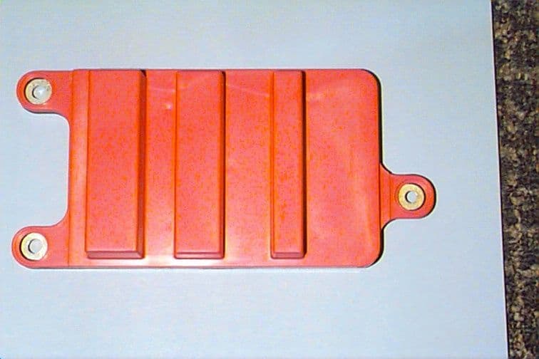
Click to zoom
Application Details
- Equipment Class
- CRR - Superregenerative Receiver
- Date of Grant
- Sep 21, 1999
- Application Purpose
- Original Equipment
- Date of Application
- Jul 13, 1999
- Equipment Note
- Remote controlled receiver
- Frequency Range
- 390.00000000 - 390.00000000
- Company
- Chamberlain Group LLC, The
- Country
- United States
Documents & Files

Document Text
Text extracted from the exhibit documents filed with the FCC. Open a document above to read the original.
Cover Letter(s)
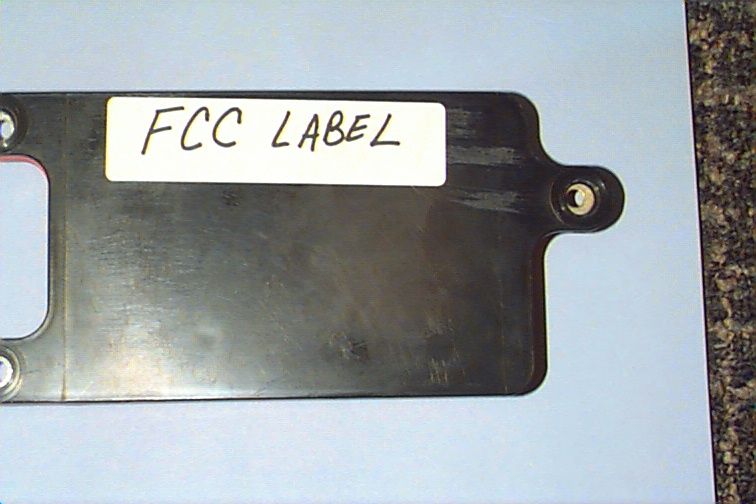
845 Larch Ave. Elmhurst, IL 60126 phone 630.993.6306 fax 630.530.6140 email: [email protected] July 14, 1999 Federal Communications Commission EQUIPMENT APPROVAL SERVICES PO Box 358315 Pittsburgh, PA 15251-5315 Re: Request for Certification Enclosed is an application, fee in the amount of $485 which includes the Request for Confidentiality fee of $135, and exhibits for certification of Superregenerative Receiver Model JCIRX which is manufactured by Chamberlain. The final instruction sheet is not available at this time, so I have included a typical instruction sheet indicating the FCC statement and important information. The FCC ID of this model, upon certification, will be HBW1304. We would appreciate your prompt attention to the submittal. Sincerely, THE CHAMBERLAIN GROUP, INC. Barbara P. Kelkhoff Manager, Product Safety LIST OF EXHIBITS Superregenerative Receiver Model JCIRX 1. Expository Statement 2. Theory of Operation 3. Schematic 4. Photographs 5. FCC Label Drawing 6. Operating Instructions 7. Test Report EXPOSITORY STATEMENT Superregenerative Receiver Model JCIRX 1. Since the final instruction sheet is not available at this time, a typical draft version has been included. The instructions include statements required to assure compliance with the Commission's Rules; Part 15. 2. Labeling is in accordance with the Commission's labeling requirements, Parts 2 and 15, Section 15.19. 3. This receiver is intended for use with certified transmitters of our manufacture only. 4. The JCIRX receiver is factory set to 390 ± 0.1% MHz.. It is not intended to be readjusted in the field, and specific instructions prohibiting tampering are provided to the user. 5. Test data for Model JCIRX is part of this submission. No emissions were detected in the forbidden bands below 1.0 GHz. Certified by: Barbara P. Kelkhoff Manager, Product Safety CIRCUIT DESCRIPTION FOR BATTERY RADIO RECEIVER MODEL JCIRX (Please refer to enclosed schematic drawing: 195D1377 Rev. C) The wire from A100 to A101 and PCB trace through R155 form an antenna. L151, L152, C152 and C153 comprise the bandpass filter tuned to 390.0 MHz. Q5, R151, R152, R153, R154 and C155 comprise an RF buffer to block back radiation from the superregenerative detector. C101 couples the buffer to the detector. T101 and C102 select the desired frequency (390 MHz ± 0.1%). Q101 bias resistors are R101, R102, R103 and R104. L102 and C106 form the self-quench network for Q101. C103 is the feedback capacitor. C104 and C105 control the junction capacitance. C107 and R105 comprise the first quench filter. L150, C150, C151, C154 and R150 isolate the detector and RF buffer from the outside world to prevent conducted RF emissions from passing through to other receivers. U4:A is a two stage active low pass filter. U4:D is a conventional audio amplifier used to bring the demodulated levels of the filter output up to a level sufficient for U4:C to digitize the data which drives the digital decoder/logic IC, U3. If the incoming code matches the programmed code the unit will either be armed or disarmed. The power supply is derived from the +12V of battery and is regulated through a 5V regulator, U1. 1. EXPOSITORY STATEMENT 2. THEORY OF OPERATION 3. SCHEMATIC 4. PHOTOGRAPHS 5. FCC LABEL DRAWING 6. OPERATING INSTRUCTIONS 7. TEST REPORT
Contact Information
Applicant
Thomas DeSilvia(Director Corporate Compliance)
Technical Specifications
| # | Rule Parts | Frequency Range | Power Output | Tolerance |
|---|---|---|---|---|
| 1 | - | 390 MHz - 390 MHz | - | % |
Other Applications from Chamberlain Group LLC, The

HBW73514
Jul 06, 2026iDock Link 2
Equipment Class
DSS - Part 15 Spread Spectrum TransmitterHBW-VKP2K
Jun 23, 2026SMART GARAGE VIDEO KEYPAD
Equipment Class
DTS - Digital Transmission System
HBWCHM1
Dec 03, 2025Wireless Chime
Equipment Class
DTS - Digital Transmission SystemHBWN519
Oct 10, 2024VEHICULAR GATE OPENER
Equipment Class
DSS - Part 15 Spread Spectrum TransmitterHBWN329
Sep 22, 2024Handheld Remote
Equipment Class
DSC - Part 15 Security/Remote Control Transmitter