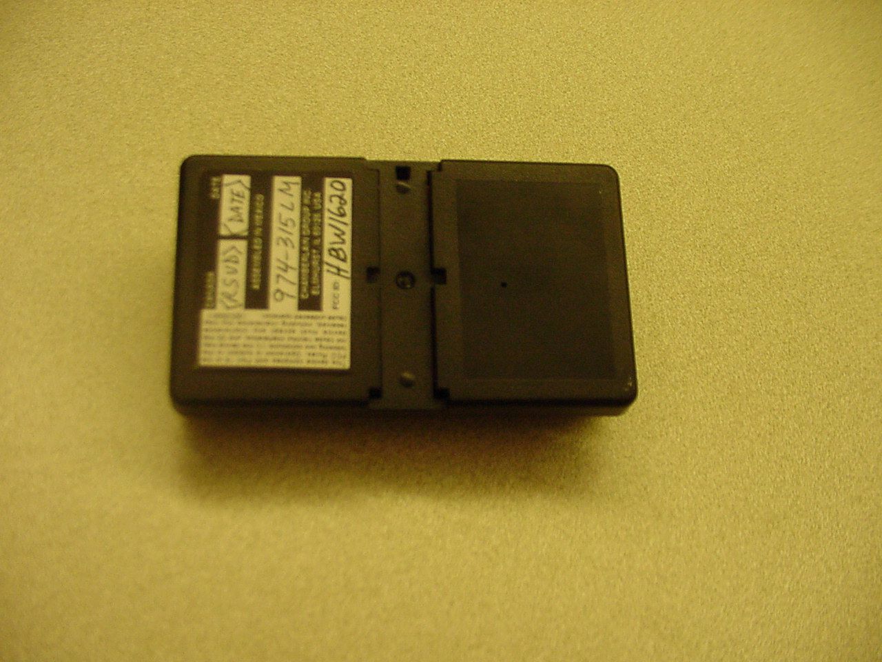
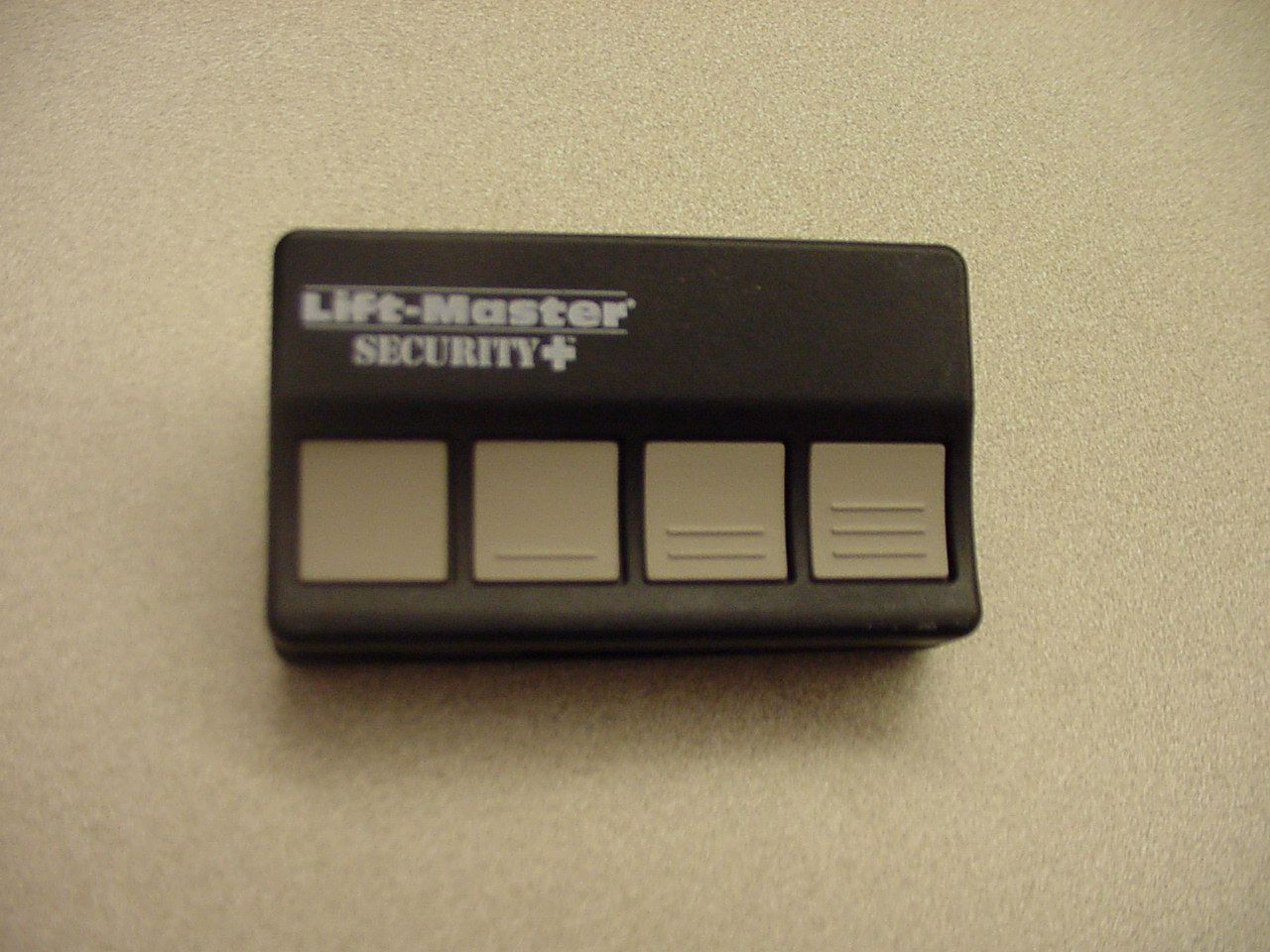
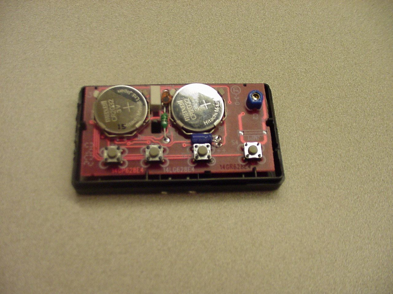
HBW1620Remote Control Transmitter
Chamberlain Group LLC, The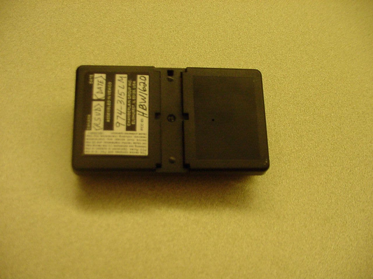
Click to zoom
Application Details
- Equipment Class
- DSC - Part 15 Security/Remote Control Transmitter
- Date of Grant
- Feb 25, 2002
- Application Purpose
- Original Equipment
- Date of Application
- Feb 25, 2002
- Equipment Note
- Remote Control Transmitter
- Frequency Range
- 315.00000000 - 315.00000000
- Company
- Chamberlain Group LLC, The
- Country
- United States
Documents & Files
Document Text
Text extracted from the exhibit documents filed with the FCC. Open a document above to read the original.
Operational Description
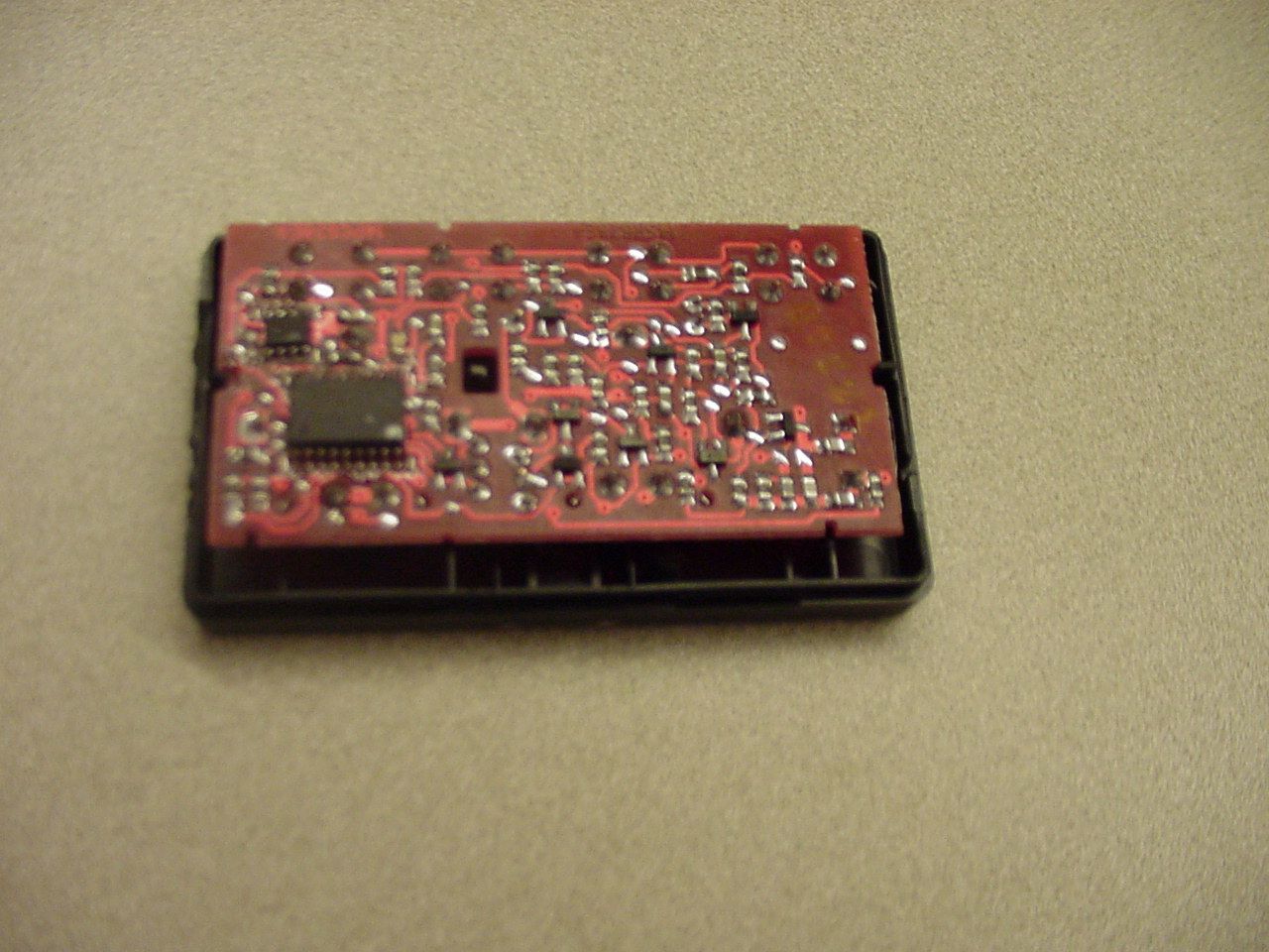
THEORY OF OPERATION AND CIRCUIT DESCRIPTION MODEL 974-315LM 4 FUNCTION, REMOTE CONTROL TRANSMITTER (Please refer to enclosed schematic drawing: 195D1620) The four-channel learning transmitter consists of a low power RF oscillator which doubles as a square-law detector (Q4 and associated components), an audio band amplifier (Q2 and associated components), a digital encoder (U1, U2, and associated components), a power latching circuit (Q1, Q3, and associated components), a switch-mode boost voltage converter (L1, Q5, and associated components), and on/off switches. The RF oscillator, Q4, is of the grounded base type. C8, C5, C7, and the copper loop set the center frequency of the oscillator at 315 MHz. C4 and C13, with the internal capacitance of Q4, establish feedback levels and harmonic suppression. R10, R11, and R12 establish dc operating conditions on Q1 and help improve temperature stability when transmitting, with R9 being held at a tri-state (floating) condition by U2. U2 and related components generate a digital code. This code is used in the companion receiver to identify a particular transmitter or function. R29 and R30 are used for harmonic suppression. To make the unit receive, R9 is held high and R10 at a tri-state (floating) condition by U2. Q4 is thus biased to a dc level, which is insufficient for oscillation. Incoming RF signals are square-law detected by Q4 and associated components and amplified by Q2 and associated components. The signal is detected by a comparator at pin 9 of U2, with the reference being a DC voltage, set by R1 and R2, at pin 10 of U2. When transmitting or receiving a radio code, the unit maintains its power through Q1, Q3, and associated components. When a button is depressed, Q1 is biased on supplying power to U2. U2 then biases Q3 on, thus keeping Q1 active for as long as necessary. When transmitting a radio code, the unit generates a 9 volt power supply for the RF circuit from its 3-6V source through the switching voltage converter formed by L1, Q5, and associated components. Q5 is periodically switched on, causing current flow through L1 at a rate, which increases linearly. When Q5 is switched off, a high voltage is generated across L1 due to instantaneous change in inductor current. This voltage is transferred across D1 and stored in C15. D3 and R24 form a feedback, which goes into pin 8 of U2, providing U2 with information about the actual voltage of the RF supply.
Schematics
REF-DESP/NDESCRIPTIONQTY B1-232D0134-2HOLDER/ +CONTACT, COIN CELL2 ITEM 310A0020BATTERY, 3V COIN CELL2 C130B0445-081CAPACITOR, LYTIC 22uF 10V1 C13SEE NOTE 1CAP SMD0805 1.8pF +/-.1 NPO1 C1430B0477CAPACITOR, LYTIC 4.7uF 16V1 C230B0431CAPACITOR, VARIABLE TOP ADJ1 C3 C6 C10-12030D710422R0CAP SMD0805 0.01uF 20% X7R5 C4 C7030D71020100CAP SMD0805 100pF 5% NPO2 C5030D76800000CAP SMD0805 6.8pF 5% NPO1 C8030D73903000CAP SMD0805 3.9pF +/-.1 NPO1 CR133B0039-3RESONATOR, CERAMIC 4MHz1 D1 D552B0065DIODE, SMD SIGNAL2 D252B0070DIODE, SMD DUAL COMMON CATHODE1 D352B0115DIODE, SMD ZENER 9.1V1 D452B0114DIODE, LED SMD805 YELLOW1 JMP1SEE NOTE 1WIRE JUMPER SPECIAL 0.30" 1" L140A0096INDUCTOR, 1000uH1 ITEM 214D0628PC BOARD1 NEGDOWN1-232C0133CONTACT, NEG COIN CELL2 Q1-2207C0069TRANSISTOR, SMD PNP SWITCH2 Q3 Q5207C0073TRANSISTOR, SMD NPN SWITCH2 Q4207C0074TRANSISTOR, SMD NPN RF1 R1311C1225RES SMD0805 1.2K 5%1 R11 R13 R20 R28 311C1025RES SMD0805 1.0K 5%4 R19 R21311C1045RES SMD0805 100K 5%2 R2 R10 R12311C1535RES SMD0805 15K 5%3 R22311C8235RES SMD0805 82K 5%1 R23311C6825RES SMD0805 6.8K 5%1 R29-30311C1015RES SMD0805 100 5%2 R3-6 R16-17 R26 R31 311C1035RES SMD0805 10K 5%8 R7-8 R14-15 R18 R24-25 R27 311C2235RES SMD0805 22K 5%8 R9311C6235RES SMD0805 62K 5%1 SW1 SW4180B0120-2SWITCH, MOMENTARY PB2 SW3 SW2SEE CHARTSWITCH, MOMENTARY PB2 U1125C0148SOIC, ELECT. ERASABLE PROM 3V1 U2SEE NOTE 1SOIC, LEARNING TX ENCODER1 NOTE 1 001A5581-2 2 CHANNEL (LEARNING CHANNEL FIXED) 001A5581-4 4 CHANNEL (LEARNING CHANNEL FIXED) 001A5581-3 2 CHANNEL (LEARNING CHANNEL ROLL) 001A5581-5 4 CHANNEL (LEARNING CHANNEL ROLL) SW2, SW3NOT USED180B0120-2NOT USED180B0120-2 U2125C0154125C0154125C0267125C0267 TEST SPEC190A0465190A0465190A0595190A0595 C13NOT USEDNOT USEDNOT USEDNOT USED JMP1NOT USEDNOT USEDNOT USEDNOT USED
Contact Information
Applicant
Thomas DeSilvia(Director Corporate Compliance)
Technical Contact
The Chamberlain Group Inc.Hank Sieradzki
[email protected]1 630 993 6564
845 Larch Avenue · Elmhurst, Illinois · United States
Test Firm
Elite Electronic Engineering Co.Daniel Crowder
Technical Specifications
| # | Rule Parts | Frequency Range | Power Output |
|---|---|---|---|
| 1 | 15.231 | 315 MHz - 315 MHz | - |
Other Applications from Chamberlain Group LLC, The

HBW73514
Jul 06, 2026iDock Link 2
Equipment Class
DSS - Part 15 Spread Spectrum TransmitterHBW-VKP2K
Jun 23, 2026SMART GARAGE VIDEO KEYPAD
Equipment Class
DTS - Digital Transmission System
HBWCHM1
Dec 03, 2025Wireless Chime
Equipment Class
DTS - Digital Transmission SystemHBWN519
Oct 10, 2024VEHICULAR GATE OPENER
Equipment Class
DSS - Part 15 Spread Spectrum TransmitterHBWN329
Sep 22, 2024Handheld Remote
Equipment Class
DSC - Part 15 Security/Remote Control Transmitter