HBW1662Remote Control Transmitter
Chamberlain Group LLC, The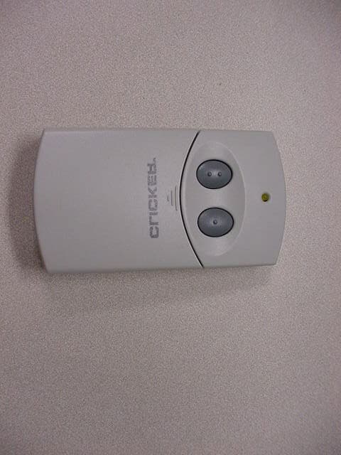
Click to zoom
Application Details
- Equipment Class
- DSC - Part 15 Security/Remote Control Transmitter
- Date of Grant
- May 25, 2006
- Application Purpose
- Original Equipment
- Date of Application
- May 25, 2006
- Equipment Note
- Remote Control Transmitter
- Frequency Range
- 390.00000000 - 390.00000000
- Company
- Chamberlain Group LLC, The
- Country
- United States
Documents & Files
Document Text
Text extracted from the exhibit documents filed with the FCC. Open a document above to read the original.
Users Manual
The Receiver DIP switch has three positions labeled “+”, “0” and “-”. The “0” setting cannot be used with the clicker remote . 1) Reset switches: 1 to “-” and positions 2 through 9 to a randomsetting using “+” and the “-”. DO NOT USE THE “O” SETTING . 2) Gather any existing remotes and open to expose the DIP switches. Resetthe DIP switch to match the newly coded receiver. Note: some three button remotes do not have a #1 switch. Match the 2 through 9 to the receiver. On three button remotesthe large button is now programmed to activate the door. 3) Test all the newly codedremote controls to be sure that they operate the door before proceeding to the BRAND MODE SETTING. After determining that the Receiver has a yellow, white or graylearn button, 1) Gather any existing remotes and open to expose the DIP switches labeled “+”, “0” and “-”. 2) Reset switches: 1 to “-” and positions 2 through 9 to a random setting using “+” and the “-”. DO NOT USE THE “0” SETTING, SET ALL REMOTES TO THE SAME SETTING. On three button remotes the large button is now programmed to activate the door. 3) The recoded remotes must beprogrammed to the receiver. Press and release the smart-learn button.Then press and hold the existing remote push button for three seconds. 4) Test all the newly coded remote controls to be sure that they operate the door before proceeding to the BRAND MODE SETTING. With this type receiver, the existing remotes do not contain DIP switches. Proceed to BRAND MODE SETTINGS. L O C K L I G H T Motor Unit & Receiver Wall Mounted Control Remote Control The clicker remote can be programmed to operate up to 2 garage door openers or gates,including different brands. All programming is done using the: • Brand switch • Transmitter DIP switch • Transmit push buttons A and B, and LED indicator Determine the BRAND of the existing garage door opener or handheld remote controls. If all remote controls are lost, the BRAND is located on the ceiling mounted motor unit or on the receiver near the flexible wire antenna. Proceed to the SECTION indicated on the BRAND chartbelow.Note: If programming to more than one opener, after programming button “A” refer to brand chart, and follow the instructions pertaining to the brand you wish to program into button “B”.When the remotes range is diminished, operation is intermittent, or the LED dims, replace thebattery. Memory is not lost when the battery is removed. Note: Dispose of old batteriesproperly. Model No. CLT 1 Universal Garage Door Opener Remote Control CLICKER Proceed to appropriate section. Step 4 - When LED flashes,release both buttons. Step 5 - Press the button you wish to operate theopener (your choice). Step 6 - Programming is complete, to test, press the button selected to activate garage door. Step 2Step 1 Existing Remote Clicker Remote Matchexistingcodes.Set extraswitches off. ➡ ➡ SECTION III • Open existing remote; determine if there are 9 or 12 code switch settings.• Set brand mode switches on clicker remote. • Program clicker remote push button. Step 1 ORANGE/REDSMART-LEARN BUTTON SECTION I SECTION II • Determine specific brand and circle above. • Open existing remote to expose code switches. • Set brand mode switches on clicker remote. • Program clicker remote push button. ➡ Chamberlain, Sears, LiftMaster, Master Mechanic, DoIt - ➡ ON ON OFF OFF OFF ON ON OFF OFF OFF OFF OFF STANLEY ON OFF OFF OFF MULTI-CODE OFF ON OFF OFF LINEAR/MOORE-O-MATIC OFF OFF ON OFF GENIE 9 SWITCH ON OFF ON OFF GENIE 12 SWITCH SECTION I - Chamberlain, Sears, LiftMaster, Master Mechanic, DoIt SECTION II - Stanley, Multi-code, Linear, Moore-O-Matic SECTION III - Genie BRAND CHART LED Button B Button A Brand Switch Dip SwitchBatterySlide battery door down & Remove Preparation Determine if your motor unit/receiver system has DIP switches or a smart-learn button.(Locate the small gray wire antenna. Somemodels require removing the light lens.)• If the Receiver has 9 DIP switches Proceed to TYPE A • If the Receiver has a yellow, white, or gray smart-learn button, proceed to TYPE B • If the Receiver has a green, red, or orange smart-learn button, proceed to TYPE C SMART-LEARNBUTTON ➡ DIP SWITCHES A TYPE B TYPE C TYPE ➡ ✚ – O 2 3 1 KG KG ➡ Use this button 2 3 1 KG KG ➡ Remote push button TECHNICAL SUPPORT: 800-442-1255 (MONDAY-FRIDAY 6AM-7PM CST; SATURDAY 8AM-6PM)Chamberlain, LiftMaster and Moore-O-Matic are Trademarks of Chamberlain Group. Genie is a Trademark of Overhead DoorCorporation. Linear and Multi-Code are Trademarks of Linear Corporation. Master Mechanic is a Trademark of TruServ. Sears is a Trademark of Sears & Roebuck. Stanley is a Trademark of The Stanley Works. DoIt is a trademark of DoIt Best Corporation. ©2001, Clicker Corporation 114A2504B All Rights Reserved Printed in Mexico ➡ Existing Remote Match existing codes. Set extraswitches off. ➡ ➡ ClickerRemote ✚ O – 1234 5 6789 RANDOM 2-9 DO NOT USE ✚ O – 1234 5 6789 RANDOM 2-9 DO NOT USE Use this button ➡ FOR TYPE A AND B ON ON ON OFF GREEN SMART-LEARNBUTTON ➡ Code switchsettings arenot used. ➡ ➡ Code switchsettings arenot used. ➡ - Stanley, Multi-Code, Linear, Moor e-O-Matic - Genie - 9 Code Switch, Genie - 12 Code Switch Step 1 - Step 1 Step 3 - Press and hold bothbuttons for 5 secondsor until LED begins toflash. Step 4 - When LED flashes,release both buttons. Step 5 - Press the button you wish to operate theopener (your choice). Step 6 - Programming is complete, to test, press the button selected to activate garage door. Step 2 Existing Remote Clicker Remote Matchexistingcodes.Set extraswitches off. ➡ ➡ Step 3 - Press and hold both buttons for 5seconds or until LEDbegins to flash. BRAND MODE SETTINGS - Set switches on clicker remote Step 2 - Press and hold both buttons for 5 seconds or until LED begins to flash. Step 3 - When LED flashes, release both buttons. Step 4 - Press the button you wish to operate the opener (your choice).For type A & B, proceed to step 6. For type C, continue on to Step 5. 2 3 1 KG KG A. Pr…
Text truncated - open the document above for the full version.
Cover Letter(s)
FCC ID: HBW1662 Request for Confidentiality In accordance with 47 C.F.R. Section 0.459, we, Chamberlain Group, Inc., hereby request confidentiality for the block diagram, schematic and product description presented for certification. In support of the Request for Confidentiality, the following is stated: Enclosed within this application is technical information which we deem to be trade secrets and proprietary. If made public, the information might be used to our disadvantage. To assist in assuring that we receive the full value of our product and protect its competitive posture, we respectfully request this grant of confidentiality. Barbara Kelkhoff Manager of Regulatory Affairs Chamberlain Group, Inc. 845 Larch Ave. Elmhurst, IL. 60126
Cover Letter(s)
845 Larch Ave. Elmhurst, IL 60126 Phone 630.993.6306 Fax 630.530.6140 Email: [email protected] May 22, 2006 Federal Communications Commission EQUIPMENT APPROVAL SERVICES PO Box 358315 Pittsburgh, PA 15251-5315 Re: Request for Certification Enclosed is an application and exhibits for Certification of a Remote Control Transmitter Model CLT1D. Circuit board assembly 1A5510CLT1D is used in Model CLT1D. I have included a typical instruction sheet indicating the FCC statement and important information. The FCC ID of this model, upon certification, will be HBW1662. We would appreciate your prompt attention to the submittal. Sincerely, THE CHAMBERLAIN GROUP, INC. Barbara Kelkhoff Manager, Regulatory Affairs LIST OF EXHIBITS REMOTE CONTROL TRANSMITTER Model CLT1D 1. Expository Statement 2. Theory of Operation 3. Schematic 4. Photographs 5. FCC Label Drawing 6. Operating Instructions 7. Test Report EXPOSITORY STATEMENT 2 FUNCTION, REMOTE CONTROL TRANSMITTER Model CLT1D 1. The instructions include statements required to assure compliance with the Commission's Rules; Part 15. 2. Labeling is in accordance with the Commission's labeling requirements, Parts 2 and 15, Section 15.19. 3. This transmitter is intended for use with the certified receivers of garage door and gate operator systems manufactured by Chamberlain , Genie , and Linear . 4. The transmitter is equipped with an automatically releasing push-button switch. Transmission is terminated upon release of the push-button. 5. Transmitter Model CLT1D is factory set to 300, 315 and 390 ± 0.1% MHz. It is not intended to be readjusted in the field, and specific instructions prohibiting tampering are provided to the user. 6. Test data for Model CLT1D is part of this submission. No emissions were detected in the forbidden bands below 1.0 GHz. Certified by: Barbara P. Kelkhoff Manager, Regulatory Affairs
Test Report
Page 1 of 17 Engineering Test Report No. 36460-01 Measurement of RF Interference from a Transmitter, Model 1A5510CLT1D Transmitter For : Chamberlain Manufacturing 845 Larch Avenue Elmhurst, IL 60126 P.O. No. : 852390 Date Received : March 23, 2006 Date Tested : March 23 and 24 and April 4, 2006 Test Personnel : Richard E. King Specification : FCC "Code of Federal Regulations” Title 47 Part 15, Subpart C Test Report By : Richard E. King EMC Engineer Approved By : Raymond J. Klouda Registered Professional Engineer of Illinois – 44894 Elite Electronic Engineering Inc. 1516 Centre Circle Downers Grove, IL 60515 Tel : (630) 495-9770 Fax: (630) 495-9785 www.elitetest.com Engineering Test Report No. 36460-01 THIS REPORT SHALL NOT BE REPRODUCED, EXCEPT IN FULL, WITHOUT THE WRITTEN APPROVAL OF ELITE ELECTRONIC ENGINEERING INCORPORATED. Page 2 of 17 Engineering Test Report No. 36460-01 THIS REPORT SHALL NOT BE REPRODUCED, EXCEPT IN FULL, WITHOUT THE WRITTEN APPROVAL OF ELITE ELECTRONIC ENGINEERING INCORPORATED. Page 3 of 17 TABLE OF CONTENTS PARAGRAPH DESCRIPTION OF CONTENTS PAGE NO. 1.0 INTRODUCTION................................................................................................................................................ 4 1.1 Description of Test Item.................................................................................................................................... 4 1.2 Purpose............................................................................................................................................................. 4 1.3 Deviations, Additions and Exclusions............................................................................................................. 4 1.4 Applicable Documents ...................................................................................................................................... 4 1.5 Subcontractor Identification .............................................................................................................................. 4 1.6 Laboratory Conditions..................................................................................................................................... 4 2.0 TEST ITEM SET-UP AND OPERATION.......................................................................................................... 4 2.1 Power Input...................................................................................................................................................... 4 2.2 Grounding......................................................................................................................................................... 5 2.3 Peripheral Equipment........................................................................................................................................ 5 2.4 Interconnect Cables........................................................................................................................................... 5 2.5 Operational Mode ............................................................................................................................................. 5 2.6 Test Item Modifications................................................................................................................................... 5 3.0 TEST EQUIPMENT............................................................................................................................................. 5 3.1 Test Equipment List .......................................................................................................................................... 5 3.2 Calibration Traceability ................................................................................................................................... 5 3.3 Measurement Uncertainty................................................................................................................................ 5 4.0 REQUIREMENTS, PROCEDURES AND RESULTS .......................................................................................5 4.1 Powerline Conducted Emissions ..................................................................................................................... 5 4.1.1 Requirements ............................................................................................................................................................ 5 4.2 Duty Cycle Factor Measurements .................................................................................................................. 5 4.2.1 Procedures................................................................................................................................................................ 5 4.2.2 Results...................................................................................................................................................................... 6 4.3 Radiated Measurements................................................................................................................................... 6 4.3.1 Requirements ............................................................................................................................................................ 6 4.3.2 Procedures................................................................................................................................................................. 7 4.3.3 Results....................................................................................................................................................................... 7 4.4 Occupied Bandwidth Measurements ............................................................................................................... 8 4.4.1 Requirement ......................................................................................................................................................…
Text truncated - open the document above for the full version.
Test Setup Photos
Figure 2 Test Set-up for Radiated Emissions Horizontal Polarity Test Set-up for Radiated Emissions Vertical Polarity
Contact Information
Applicant
Thomas DeSilvia(Director Corporate Compliance)
Technical Contact
Chamberlain Group Inc, TheHank Sieradzki
[email protected]630-993-6564
845 Larch Avenue · Elmhurst, Illinois · United States
Test Firm
Elite Electronic Engineering Co.Daniel Crowder
Technical Specifications
| # | Rule Parts | Frequency Range | Power Output |
|---|---|---|---|
| 3 | 15.231 | 390 MHz - 390 MHz | - |
Other Applications from Chamberlain Group LLC, The

HBW73514
Jul 06, 2026iDock Link 2
Equipment Class
DSS - Part 15 Spread Spectrum TransmitterHBW-VKP2K
Jun 23, 2026SMART GARAGE VIDEO KEYPAD
Equipment Class
DTS - Digital Transmission System
HBWCHM1
Dec 03, 2025Wireless Chime
Equipment Class
DTS - Digital Transmission SystemHBWN519
Oct 10, 2024VEHICULAR GATE OPENER
Equipment Class
DSS - Part 15 Spread Spectrum TransmitterHBWN329
Sep 22, 2024Handheld Remote
Equipment Class
DSC - Part 15 Security/Remote Control Transmitter