HBW190A1808-1Keypad Access Control
Chamberlain Group LLC, The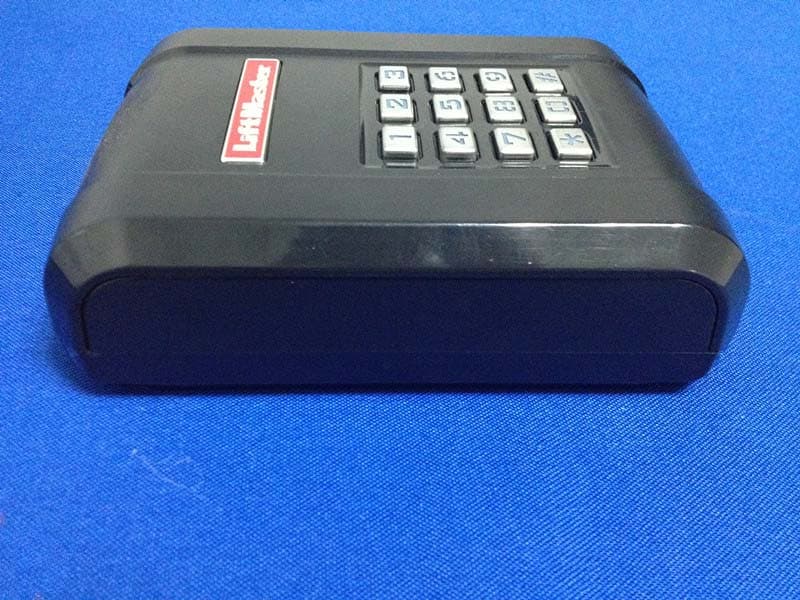
Click to zoom
Application Details
- Equipment Class
- DSC - Part 15 Security/Remote Control Transmitter
- Date of Grant
- Mar 17, 2015
- Application Purpose
- Original Equipment
- Date of Application
- Mar 17, 2015
- Equipment Note
- Keypad Access Control
- Frequency Range
- 390.00000000 - 390.00000000
- Company
- Chamberlain Group LLC, The
- Country
- United States
Documents & Files
Document Text
Text extracted from the exhibit documents filed with the FCC. Open a document above to read the original.
Users Manual
1 OVERVIEW The Wireless Commercial Keypad comes with one 9V Lithium battery, instructions, and two keys. A wireless signal is transmitted when a valid 4-digit PIN and the # key is pressed. A long tone will sound. The keypad backlight will illuminate for 15 seconds when any key is pressed. If an invalid PIN or partial PIN is accidentally entered, an error tone will sound. The Wireless Commercial Keypad is compatible with the brands of commercial door and gate operators listed in the table below. Wireless Commercial Keypad Models KPW5 and KPW250 MODELFREQUENCY AND ENCRYPTIONPIN CAPACITY KPW5LiftMaster Security+ 2.0™ Default Tri-band 390 MHz, 315 MHz, and 310 MHz Up to 5 permanent PINs and Up to 10 unique temporary PINs KPW250LiftMaster Security+ 2.0™ Default Tri-band 390 MHz, 315 MHz, and 310 MHz Up to 250 permanent PINs and Up to 10 unique temporary PINs LiftMaster Security+ ® 315 MHz LiftMaster Security+ ® 390 MHz Linear Multi-Code 300 MHz Specifi cations Power . . . . . . . . . . . . . . . . . . . . . . . . . . . . . . . . . . . . . . . . . . .9V lithium battery Operating temperature range . . . . . . . . . . . . . . . . . . . . . . . . . -40°F to 140°F (-40°C to +60°C) Storage and shipping temperature range . . . . . . . . . . . . . . .-40°F to 140°F (-40°C to +60°C) Enclosure . . . . . . . . . . . . . . . . . . . . . . . . . . . . . . . . . . . . . . . . .NEMA 3R KPW5KPW250 2 INSTALLATION 1. Choose a mounting location suitable for your application such as a wall, flat surface, or a pedestal with a 3" x 3" mounting pattern (LiftMaster gooseneck pedestal post models PED42 or PED64). 2. Unlock and remove the faceplate from the mounting plate. 3. Mount the mounting plate to the desired surface and secure with 1/4" screws or bolts (not provided). 4. Remove the battery cover using a Phillips screw driver. Install the battery (provided) and re-install inner cover. 5. Reattach the faceplate to the mounting plate and lock with the key. BASIC PROGRAMMING The Wireless Commercial Keypad must be put into programming mode prior to any of the programming steps below unless otherwise indicated. The keypad backlight will remain on if the product is in programming mode. While in programming mode, if an invalid code is entered, an error tone will sound, but the keypad will remain in programming mode. After 60 seconds of inactivity, the keypad will exit the programming mode. The 6-digit Master Code is used to prevent unauthorized access to the system. A Master Code is required (factory default code: 888888) to operate the Wireless Commercial Keypad. It is highly recommended to change and record your unique Master Code. Set Master Code Program a PIN To prevent possible SERIOUS INJURY or DEATH from a moving gate or door: • ALWAYS keep remote controls out of reach of children. NEVER permit children to operate or play with remote controls. • Activate gate or door ONLY when it can be seen clearly, is properly adjusted, and there are no obstructions to door travel. • ALWAYS keep gate or door in sight until completely closed. NEVER permit anyone to cross path of moving gate or door. Programming StepKeystroke CombinationIndicator 1. Enter program mode * (Master Code) # Long tone 2. Update Master Code09 # (New 6-digit Code) # (New 6-digit Code) # Long tone 3. Exit Program Mode * * # Keypad backlight will turn off Programming StepKeystroke CombinationIndicator 1. Enter program mode * (Master Code) # Long tone 2. Set new pin01 # (New 4-digit PIN) # (new 4-digit PIN) #Long tone 3. Exit Program Mode * * # Keypad backlight will turn off NOTE: An error tone will sound if the maximum number of PINs is exceeded or if user tries to program a PIN already programmed in the memory. Battery Mounting plate Faceplate Battery Cover 3 LiftMaster NOTE: The Master Code and a PIN need to be set before the gate operator can be programmed. See Basic Programming, page 2. KPW5 - The frequency and encryption are set at the factory. Proceed to Step 4. KPW250 - The frequency and encryption are set at the factory for LiftMaster Security+ 2.0 (tri-band 310, 315, and 390 MHz) operators. Proceed to Step 4. For LiftMaster Security+ (315 MHz or 390 MHz), the frequency and encryption need to be set. Proceed to Step 1. 1. Enter program mode: * (Master Code) # 2 Set frequency and encryption (KPW250 only): • LiftMaster Security+ 315 MHz - Press 03 # 2 #. A long tone will sound. • LiftMaster Security+ 390 MHz - Press 03 # 3 #. A long tone will sound. • To reset factory default - Press 03 # 1 #. A long tone will sound. 3. Exit Program Mode: * * #. 4. Press the Learn Button on the operator. 5. Within 30 seconds- Enter a valid 4-digit PIN then press #. A long tone will sound. PROGRAM TO OPERATOR Linear Multi-Code KPW250 ONLY 1. Locate the DIP switch sequence on the operator and record it. If DIP switch is in the “up” or “on” (CLOSED) position place a 1, “down” or “off” (OPEN) position place a 0 in the corresponding box in the chart below. NOTE: Leave any unused switch locations blank. Write the DIP switch 10-digit sequence: ___ ___ ___ ___ ___ ___ ___ ___ ___ ___ 2. Enter program mode: * (Master Code) #. A long tone will sound. 3. Set Linear Multi-Code frequency and encryption: Press 03 # 4 #. A long tone will sound. 4. Enter the DIP Switch sequence (Use ONLY 1 and 0). Press #. A long tone will sound. 3. Exit Program Mode: * * #. NOTE: When entering the DIP Switch sequence 3 beeps will sound if an incorrect number of entries is input. DIP Switch Sequence12345678910 UP / ON (CLOSED) DOWN / OFF (OPEN) Once an operator has been programmed, enter a valid 4-digit PIN and the # key to activate the operator. 4 ADDITIONAL PROGRAMMING The Wireless Commercial Keypad must be put into programming mode prior to any of the programming steps below unless otherwise indicated. Set Temporary PIN A temporary 4-digit PIN can be programmed to allow access to visitors (maximum of 9 uses). The temporary PIN cannot be the same as any previously programmed PIN. The keypad will …
Text truncated - open the document above for the full version.
Cover Letter(s)
Chamberlain Group Inc, The Letter of Authorization Company: Chamberlain Group Inc, The Address: 845 Larch Avenue, Elmhurst, IL 60126 Product Name: Keypad Access Controller Model Number: KPW5 We authorize MiCOM Labs Inc, 575 Boulder Court, Pleasanton, CA 94566, USA, to act on our behalf on all matters concerning the above named equipment. Any individual within MiCOM Labs is authorized to act on our behalf and take action on the application. This shall include the following: • Testing • Approval applications (includes complete product documentation package, including Confidential information) and procedures • Payment of approval fees We declare that MiCOM Labs Inc, 575 Boulder Court, Pleasanton, CA 94566, USA, is allowed to forward all information related to the approval project to the applied notified body and to the notification entities and to discuss any issues concerning the approval application. Any and all acts carried out by MiCOM Labs on our behalf shall have the same effect as acts of our own. Name: Barbara Kelkhoff Date: 2015.01.26 Title: Manager of Regulatory Affairs Signature of applicant:
Cover Letter(s)
< Chamberlain Group Inc, The > Office of Engineering Technology Federal Communications Commission 7435 Oakland Mills Road Columbia, MD 21046 Date:2015.01.26 Subject; Request for Confidentiality FCC ID: HBW190A1808-1 To Whom It May Concern, Pursuant to the provisions of Sections 0.457 and 0.459 of Commission's rules (47CFR0.457, 0.459), we are requesting the Commission to withhold the following attachment(s) as confidential document from public disclosure indefinitely. • Schematic Diagram • Block Diagram • Operational Description Above mentioned document contains detailed system and equipment description are considered as proprietary information in operation of the equipment. The public disclosure of above documents might be harmful to our company and would give competitor an unfair advantage in the market. It is our understanding that all measurement test reports, FCC ID label format and correspondent during certification review process cannot be granted as confidential documents and those information will be available for public review once the grant of equipment authorization is issued. Sincerely, Signature: Name: Barbara Kelkhoff Title: Manager of Regulatory Affairs
External Photos
External photos
ID Label/Location Info
LABEL ARTWORK AND LOCATION Remark: The FCC Statement is seen in user manual. FCC ID Location
Internal Photos
Internal photos
Test Report
Report No: TCT150209E007 The results detailed in this test report relate only to the specific sample(s) tested. and the test results show that the equipment under test (EUT) is in compliance with the FCC requirements. This report is not to be reproduced except in full, without written approval from Tongce Testing Lab. Test REPORT Applicant: Chamberlain Group Inc, The Address of Applicant: 845 Larch Avenue, Elmhurst, IL 60126 Equipment Under Test (EUT) Product Name: Keypad Access Controller Model No.: KPW5 FCC ID: HBW190A1808-1 Applicable standards: FCC CFR Title 47 Part 15 Subpart C Section 15.231; RSS 210; RSS-Gen Date of sample receipt: Feb. 09, 2015 Date of Test: Feb. 10,to Mar. 09, 2015 Date of report issued: Mar. 10, 2015 Test Result : PASS * * In the configuration tested, the EUT complied with the standards specified above. Report No: TCT150209E007 Hotline: 400-6611-140 Tel: 86-755-27673339 Fax: 86-755-27673332 http://www.tct-lab.com Page 2 of 27 2 Version Version No. Date Description 00 Mar. 10, 2015 Original Prepared By: Date: Mar. 10, 2015 Report Clerk Check By: Date: Mar. 10, 2015 EMC Manger Report No: TCT150209E007 Hotline: 400-6611-140 Tel: 86-755-27673339 Fax: 86-755-27673332 http://www.tct-lab.com Page 3 of 27 3 Contents Page 1 COVER PAGE ............................................................................................................................... .........1 2 Version............................................................................................................................................................................... 2 3 Contents............................................................................................................................................................................. 3 4 Test Summary................................................................................................................................................................... 4 5 General Information........................................................................................................................................................ 5 5.1 Client Information..................................................................................................................................................... 5 5.2 General Description of E.U.T.................................................................................................................................. 5 5.3 Test mode.................................................................................................................................................................. 6 5.4 Description of Support Units................................................................................................................................... 6 5.5 Laboratory Facility.................................................................................................................................................... 6 5.6 Measuremet uncertainty.......................................................................................................................................... 7 5.7 Laboratory Location................................................................................................................................................. 7 5.8 Other Information Requested by the Customer................................................................................................... 7 5.9 Test Instruments list................................................................................................................................................. 8 6 Test results and Measurement Data........................................................................................................................... 9 6.1 Antenna requirement:.............................................................................................................................................. 9 6.2 Conducted Emission.............................................................................................................................................. 10 6.3 Radiated Emission................................................................................................................................................. 11 6.4 Bandwidth Test....................................................................................................................................................... 23 6.5 Manually Activated Transmitter ................................................................................................................. 26 Report No: TCT150209E007 Hotline: 400-6611-140 Tel: 86-755-27673339 Fax: 86-755-27673332 http://www.tct-lab.com Page 4 of 27 4 Test Summary Test Item Section in CFR 47 Result Antenna requirement 15.203 Pass AC Power Line Conducted Emission 15.207; RSS-Gen N.A. Manually Activated Transmitter 15.231(a); RSS-210 Pass Radiation Emission 15.231(b), 15.205, 15.209, 15.35; RSS-210; RSS-Gen Pass Occupied Bandwidth 15.231(c); RSS-210 Pass Pass: The EUT comply with the essential requirements in the standard. Report No: TCT150209E007 Hotline: 400-6611-140 Tel: 86-755-27673339 Fax: 86-755-27673332 http://www.tct-lab.com Page 5 of 27 5 General Information 5.1 Client Information Applicant: Chamberlain Group Inc, The Address of Applicant: 845 Larch Avenue, Elmhurst, IL 60126 Manufacturer: Chamberlain Group Inc, The Address of Manufacturer: 845 Larch Avenue, Elmhurst, IL 60126 5.2 General Description of E.U.T. Product Name: Keypad Access Controller Model No.: KPW5 Brand Name: Liftmaster Operation Frequency: 310M, 315M, 390M Modulation type: OOK Antenna Type: Internal antenna Antenna gain: 0dBi Power supply: DC 9V Battery Note: 1. For a more detailed features description, please refer to the manufacturer’s specifications or the User's Manual. Report No: TCT150209E007 Hotline: 400-6611-140 Tel: 86-755-27673339 Fax: 86-755-27673332 http://www.tct…
Text truncated - open the document above for the full version.
Contact Information
Applicant
Thomas DeSilvia(Director Corporate Compliance)
Technical Contact
Shenzhen Tongce Testing LabJoe Zhou
[email protected](86)75536638142
1F, Leinuo Watch Building, Fuyong Town, Baoan Dist · Shenzhen · China
Test Firm
Shenzhen Tongce Testing LabJoe Zhou
[email protected]860755-36638142
Technical Specifications
| # | Rule Parts | Frequency Range | Power Output |
|---|---|---|---|
| 2 | 15.231 | 390 MHz - 390 MHz | - |
Other Applications from Chamberlain Group LLC, The

HBW73514
Jul 06, 2026iDock Link 2
Equipment Class
DSS - Part 15 Spread Spectrum TransmitterHBW-VKP2K
Jun 23, 2026SMART GARAGE VIDEO KEYPAD
Equipment Class
DTS - Digital Transmission System
HBWCHM1
Dec 03, 2025Wireless Chime
Equipment Class
DTS - Digital Transmission SystemHBWN519
Oct 10, 2024VEHICULAR GATE OPENER
Equipment Class
DSS - Part 15 Spread Spectrum TransmitterHBWN329
Sep 22, 2024Handheld Remote
Equipment Class
DSC - Part 15 Security/Remote Control Transmitter