HBW1A5247Garage Door Opener Transmitter
Chamberlain Group LLC, The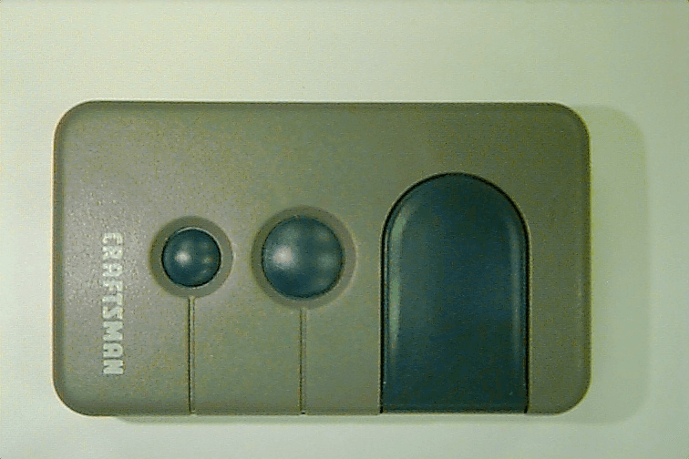
Click to zoom
Application Details
- Equipment Class
- DSC - Part 15 Security/Remote Control Transmitter
- Date of Grant
- Jan 31, 1999
- Application Purpose
- Original Equipment
- Date of Application
- Nov 19, 1998
- Equipment Note
- Garage Door Opener Transmitter
- Frequency Range
- 390.00000000 - 390.00000000
- Company
- Chamberlain Group LLC, The
- Country
- United States
Documents & Files
Document Text
Text extracted from the exhibit documents filed with the FCC. Open a document above to read the original.
Cover Letter(s)
845 Larch Ave. Elmhurst, IL 60126 phone 630.993.6306 fax 630.530.6140 email: [email protected] November 20, 1998 Federal Communications Commission EQUIPMENT APPROVAL SERVICES PO Box 358315 Pittsburgh, PA 15251-5315 Re: Request for Certification Enclosed is an application, fee in the amount of $940, and exhibits for Certification of a Remote Control Transmitter, Model 1A5247. The final instruction sheet is not available at this time, so I have included a typical instruction sheet indicating the FCC statement and important information. The FCC ID of this model, upon certification, will be HBW1A5247. We would appreciate your prompt attention to the submittal. Sincerely, THE CHAMBERLAIN GROUP, INC. Barbara P. Kelkhoff Manager, Product Safety LIST OF EXHIBITS 3 FUNCTION, REMOTE CONTROL TRANSMITTER MODEL 1A5247 1. Expository Statement 2. Theory of Operation 3. Schematic 4. Photographs 5. FCC Label Drawing 6. Operating Instructions 7. Test Report EXPOSITORY STATEMENT 3 FUNCTION, REMOTE CONTROL TRANSMITTER MODEL 1A5247 1. Since the final instruction sheet is not available at this time, a marked-up typical version has been included. The instructions include statements required to assure compliance with the Commission's Rules; Part 15. 2. Labeling is in accordance with the Commission's labeling requirements, Parts 2 and 15, Section 15.19. 3. This transmitter is intended for use with the certified receivers of our manufacture only. 4. The transmitter is equipped with an automatically releasing push-button switch. Transmission is terminated upon release of the push-button. 5. The 1A5247 is factory set to 390 ± 0.1% MHz. It is not intended to be readjusted in the field, and specific instruction prohibiting tampering are provided to the user. 6. Test data for the Model 1A5247 is part of this submission. No emissions were detected in the forbidden bands below 1.0 GHz. Certified by: Barbara P. Kelkhoff Manager, Product Safety THEORY OF OPERATION AND CIRCUIT DESCRIPTION MODEL 1A5247 3 FUNCTION, REMOTE CONTROL TRANSMITTER (Please refer to enclosed schematic drawing: 195D1255D) The 1A5247 transmitter consists of a low power RF oscillator (Q1 and associated components), a digital encoder (U1 and related components), and on/off switches. The RF oscillator, Q1, is of the grounded base type. C4, C5, C6, C7, and the copper loop, L2, set the center frequency of the oscillator at 390 MHz. C3, L1, L2 and C2, with the internal capacitance of Q1, establish feedback levels and harmonic suppression. R3, R4 and R6 establish dc operating conditions on Q1 and help improve temperature stability. U1 and related components generate a digital code. This code is used in the companion receiver to identify a particular transmitter or functions. The 3V battery circuit is equipped with an automatically releasing (normally off) push-button switches. D1, D2, and D3 supply voltage to Q1 and U1 when SW1, SW2 or SW3 are depressed. SW1-SW3, and related components, R1, R2, R7-R9 and and U1 provide three input functions. The digital signal at U1 (pin 1) is randomly programmed at our factory location. 1. EXPOSITORY STATEMENT 2. THEORY OF OPERATION 3. SCHEMATIC 4. PHOTOGRAPHS 5. FCC LABEL DRAWING 6. OPERATING INSTRUCTIONS 7. TEST REPORT
Internal Photos
SrsLbl 1A5247 SrsTop 1A5247 SrsCase 1A5247
Operational Description
845 Larch Ave. Elmhurst, IL 60126 phone 630.993.6306 fax 630.530.6140 email: [email protected] November 20, 1998 Federal Communications Commission EQUIPMENT APPROVAL SERVICES PO Box 358315 Pittsburgh, PA 15251-5315 Re: Request for Certification Enclosed is an application, fee in the amount of $940, and exhibits for Certification of a Remote Control Transmitter, Model 1A5247. The final instruction sheet is not available at this time, so I have included a typical instruction sheet indicating the FCC statement and important information. The FCC ID of this model, upon certification, will be HBW1A5247. We would appreciate your prompt attention to the submittal. Sincerely, THE CHAMBERLAIN GROUP, INC. Barbara P. Kelkhoff Manager, Product Safety LIST OF EXHIBITS 3 FUNCTION, REMOTE CONTROL TRANSMITTER MODEL 1A5247 1. Expository Statement 2. Theory of Operation 3. Schematic 4. Photographs 5. FCC Label Drawing 6. Operating Instructions 7. Test Report EXPOSITORY STATEMENT 3 FUNCTION, REMOTE CONTROL TRANSMITTER MODEL 1A5247 1. Since the final instruction sheet is not available at this time, a marked-up typical version has been included. The instructions include statements required to assure compliance with the Commission's Rules; Part 15. 2. Labeling is in accordance with the Commission's labeling requirements, Parts 2 and 15, Section 15.19. 3. This transmitter is intended for use with the certified receivers of our manufacture only. 4. The transmitter is equipped with an automatically releasing push-button switch. Transmission is terminated upon release of the push-button. 5. The 1A5247 is factory set to 390 ± 0.1% MHz. It is not intended to be readjusted in the field, and specific instruction prohibiting tampering are provided to the user. 6. Test data for the Model 1A5247 is part of this submission. No emissions were detected in the forbidden bands below 1.0 GHz. Certified by: Barbara P. Kelkhoff Manager, Product Safety THEORY OF OPERATION AND CIRCUIT DESCRIPTION MODEL 1A5247 3 FUNCTION, REMOTE CONTROL TRANSMITTER (Please refer to enclosed schematic drawing: 195D1255D) The 1A5247 transmitter consists of a low power RF oscillator (Q1 and associated components), a digital encoder (U1 and related components), and on/off switches. The RF oscillator, Q1, is of the grounded base type. C4, C5, C6, C7, and the copper loop, L2, set the center frequency of the oscillator at 390 MHz. C3, L1, L2 and C2, with the internal capacitance of Q1, establish feedback levels and harmonic suppression. R3, R4 and R6 establish dc operating conditions on Q1 and help improve temperature stability. U1 and related components generate a digital code. This code is used in the companion receiver to identify a particular transmitter or functions. The 3V battery circuit is equipped with an automatically releasing (normally off) push-button switches. D1, D2, and D3 supply voltage to Q1 and U1 when SW1, SW2 or SW3 are depressed. SW1-SW3, and related components, R1, R2, R7-R9 and and U1 provide three input functions. The digital signal at U1 (pin 1) is randomly programmed at our factory location. 1. EXPOSITORY STATEMENT 2. THEORY OF OPERATION 3. SCHEMATIC 4. PHOTOGRAPHS 5. FCC LABEL DRAWING 6. OPERATING INSTRUCTIONS 7. TEST REPORT
Test Report
L. S. COMPLIANCE, Inc. FCC ID: HBW1A5247 LSC-Chamberlain 80232of 25 0 COMPLIANCE TESTING OF CHAMBERLAIN 3 BUTTON REMOTE CONTROL TRANSMITTER - TEST REPORT - NOVEMBER 11, 1998 Prepared for: The Chamberlain Group Elmhurst, Illinois 60126 All results of this report relate only to the items that were tested. This report is not to be reproduced, except in full, without written approval of L.S.Compliance, Inc. L. S. COMPLIANCE, Inc. FCC ID: HBW1A5247 LSC-Chamberlain 80232of 25 1 SectionDescriptionPage # Report of Measurements: index1 Description of Measurement Facilities2 1.2Signature Page3 1.3Summary of Test Report4 1.4Introduction5 1.5Purpose5 1.6Radiated Emission Test Setup5 1.7Radiated Emission Test Procedure6 1.8Radiated Emission Test Equipment Utilized7 1.9Conducted Emission Measurements7 1.10Restricted Bands (Frequencies and Limits)8 1.11Photos taken during testing9 1.12Summary of Results and Conclusions11 1.13Test Equipment List12 Appendices ASample Calculations:13 i.Calculation of Radiated Emissions Limits14 ii.Duty Cycle Correction Factor Calculation15 iii.Occupied Bandwidth Calculations16 BData Charts17 CGraphs19 L. S. COMPLIANCE, Inc. FCC ID: HBW1A5247 LSC-Chamberlain 80232of 25 2 DESCRIPTION OF MEASUREMENT FACILITIES Site on File with the FCC ID Number: 31040/SIT 1300F2 “ The site referenced above has been found to comply with the test site criteria found in ANSI C63.4-1992 and 47CFR Section 2.948.” L. S. COMPLIANCE, Inc. FCC ID: HBW1A5247 LSC-Chamberlain 80232of 25 3 SIGNATURE PAGE Prepared By: Approved By: Kenneth L.Boston 11 Nov1998 Kenneth L. Boston, EMC Lab Manager Date PE #31926 Registered Professional Engineer (State of Wisconsin) L. S. COMPLIANCE, Inc. FCC ID: HBW1A5247 LSC-Chamberlain 80232of 25 4 L. S. COMPLIANCE, Inc. FCC ID: HBW1A5247 LSC-Chamberlain 80232of 25 5 1.3SUMMARY OF TEST REPORT MANUFACTURER:The Chamberlain Group MODEL:Craftsman 3 Channel Transmitter; 1A5247 SERIAL:LS08 DESCRIPTION:Low power Remote Transmitter FREQUENCY RANGE:390 MHz The Craftsman 3 button Remote control was found to “meet” the radiated emission specification of Title 47 CFR FCC, Part 15, subpart C. for an intentional radiator This Remote Control device is meant to control the operation of a Garage Door lifting mechanism, from a distance of up to 150 feet or more. The associated control receiver is part of this system, and has been certified at an earlier date. L. S. COMPLIANCE, Inc. FCC ID: HBW1A5247 LSC-Chamberlain 80232of 25 6 1.4 INTRODUCTION On November 2 and 11 of 1998, a series of Radiated Emissions tests were performed on a sample model of the Craftsman 3 button Remote, a Remote control which operates a garage door by means of a short burst of data transmission containing an I.D. code. These tests were performed using the test procedures outlined in ANSI C63.4-1992 for intentional radiators, and in accordance with the limits set forth in FCC Part 15.231a,b for a periodic transmitter. These tests were performed by Kenneth L. Boston, PE, of L. S. Compliance, Inc. 1.5 PURPOSE The above mentioned tests were performed in order to determine the compliance of Craftsman 3 button Remote product with limits contained in various provisions of Title 47 CFR, FCC Part 15, including: 15.20515.231b 15.209 15.231c All radiated emissions tests were performed to measure the emissions in the frequency bands described by the above sections, and to determine whether said emissions are below the limits established by the above sections. These tests were performed in accordance with the procedure described in the American National Standard for methods of measurement of Radio-Noise Emissions from Low-Voltage Electrical and Electronic Equipment in the Range of 9 kHz to 40 GHz (ANSI C63.4-1992). Another document used as reference for the EMI receiver specification was the International Special Committee on Radio Interference (CISPR) number 16-1 (1993). 1.6 RADIATED EMISSIONS TEST SETUP The test sample was operated within the 3 meter Semi-Anechoic, FCC listed chamber located at L.S. Compliance in Cedarburg, WI. The sample was placed on an 80cm high wooden pedestal, which was centered on the flush-mounted 2m diameter metal turntable. The test sample was operated on its own [new] internal battery. The test sample was configured to run in a continuous transmit mode during the 15.231c and 15.231b measurements. This was accomplished by the use of a small Plexiglas stand, which had a plastic plunger simulating a finger, which held down on of the activating buttons. The three buttons were all activated to transmit, and the large button gave the highest emission signature, and was used for all the testing. One test sample, set to operate on the standard channel, was tested as an intentional radiator, in order to determine compliance at a frequency of 390 MHz, Please refer to Section 1.11 for pictures of the test setup. L. S. COMPLIANCE, Inc. FCC ID: HBW1A5247 LSC-Chamberlain 80232of 25 7 1.7 RADIATED EMISSION TEST PROCEDURE The fundamental and spurious (harmonic) emissions of the transmitter were tested for compliance to Title 47 CFR, FCC Part 15.231b limits for periodic devices. For the calculations used to determine the limits applicable for the test sample, refer to Appendix A. These limits are expressed in decibels (dB) above 1 microvolt per meter (μV/m). The sample was tested from the lowest frequency generated by the transmitter (without going below 9 kHz) to the 10th harmonic of the fundamental frequency generated by the device. The appropriate limits were also observed when the fundamental or spurious signals were located within any of the restricted bands as described in Part 15.205a. These frequencies, and their associated limits, are referenced in Section 7.10. The sample was placed on a nonconductive (wooden) pedestal in the 3 Meter chamber and the antenna mast was placed such that the antenna was 3m from the test object. A biconical antenna or tuned dipole was used to measure emissions from 30 to 200 MHz, a …
Text truncated - open the document above for the full version.
Test Report
L. S. COMPLIANCE, Inc. FCC ID: HBW1A5247 LSC-Chamberlain 80224pageof 24 0 FCC CERTIFICATION TESTING OF SEARS (craftsman) 3 BUTTON REMOTE CONTROL TRANSMITTER - TEST REPORT - JANUARY 11, 1999 Prepared for: The Chamberlain Group L. S. COMPLIANCE, Inc. FCC ID: HBW1A5247 LSC-Chamberlain 80224pageof 24 1 SectionDescriptionPage # Report of Measurements: index1 Description of Measurement Facilities2 1.2Signature Page3 1.3Summary of Test Report4 1.4Introduction5 1.5Purpose5 1.6Radiated Emission Test Setup5 1.7Radiated Emission Test Procedure6 1.8Radiated Emission Test Equipment Utilized7 1.9Conducted Emission Measurements7 1.10Restricted Bands (Frequencies and Limits)8 1.11Photos taken during testing9 1.12Summary of Results and Conclusions10 1.13Test Equipment List11 Appendices ASample Calculations:12 i.Calculation of Radiated Emissions Limits13 ii.Duty Cycle Correction Factor Calculation14 iii.Occupied Bandwidth Calculations15 BData Charts16 CGraphs18 L. S. COMPLIANCE, Inc. FCC ID: HBW1A5247 LSC-Chamberlain 80224pageof 24 2 DESCRIPTION OF MEASUREMENT FACILITIES Site on File with the FCC ID Number: 31040/SIT 1300F2 “ The site referenced above has been found to comply with the test site criteria found in ANSI C63.4-1992 and 47CFR Section 2.948.” L. S. COMPLIANCE, Inc. FCC ID: HBW1A5247 LSC-Chamberlain 80224pageof 24 3 SIGNATURE PAGE Prepared By: Approved By: Kenneth L.Boston January 11, 1999 Kenneth L. Boston, EMC Lab ManagerDate PE #31926 Registered Professional Engineer (State of Wisconsin) L. S. COMPLIANCE, Inc. FCC ID: HBW1A5247 LSC-Chamberlain 80224pageof 24 4 1.3SUMMARY OF TEST REPORT MANUFACTURER:Chamberlain MODEL:Craftsman 3 button Remote SERIAL:LS05 DESCRIPTION:Low power Remote Transmitter FREQUENCY RANGE:390 MHz The Craftsman 3 button Remote control was found to “meet” the radiated emission specification of Title 47 CFR FCC, Part 15, subpart C. for an intentional radiator This Remote Control device is meant to control the operation of a Garage Door lifting mechanism, from a distance of up to 150 feet or more. The associated control receiver is part of this system, and has been certified at an earlier date. L. S. COMPLIANCE, Inc. FCC ID: HBW1A5247 LSC-Chamberlain 80224pageof 24 5 1.4 INTRODUCTION On November 2, and December 21 of 1998, and January 6, 1999, a series of Radiated Emissions tests were performed on a sample model of the Craftsman 3 button Remote, a Remote control which operates a garage door by means of a short burst of data transmission containing an I.D. code. These tests were performed using the test procedures outlined in ANSI C63.4-1992 for intentional radiators, and in accordance with the limits set forth in FCC Part 15.231a,b for a periodic transmitter. These tests were performed by Kenneth L. Boston, PE, of L. S. Compliance, Inc. 1.5 PURPOSE The above mentioned tests were performed in order to determine the compliance of Craftsman 3 button Remote product with limits contained in various provisions of Title 47 CFR, FCC Part 15, including: 15.20515.231b 15.209 15.231c All radiated emissions tests were performed to measure the emissions in the frequency bands described by the above sections, and to determine whether said emissions are below the limits established by the above sections. These tests were performed in accordance with the procedure described in the American National Standard for methods of measurement of Radio-Noise Emissions from Low-Voltage Electrical and Electronic Equipment in the Range of 9 kHz to 40 GHz (ANSI C63.4-1992). Another document used as reference for the EMI receiver specification was the International Special Committee on Radio Interference (CISPR) number 16-1 (1993). 1.6 RADIATED EMISSIONS TEST SETUP The test sample was operated within the 3 meter Semi-Anechoic, FCC listed chamber located at L.S. Compliance in Cedarburg, WI. The sample was placed on an 80cm high wooden pedestal, which was centered on the flush-mounted 2m diameter metal turntable. The test sample was operated on its own [new] internal battery. The test sample was configured to run in a continuous transmit mode during the 15.231c and 15.231b measurements. This was accomplished by the use of a small Plexiglas stand, which had a plastic plunger simulating a finger, which held down one of the activating buttons. The three buttons were all activated to transmit, and the large button gave the highest emission signature, and was used for all the testing. One test sample set to operate on the standard channel was tested as an intentional radiator, in order to determine compliance at a frequency of 390 MHz, Please refer to Section 1.11 for pictures of the test setup. L. S. COMPLIANCE, Inc. FCC ID: HBW1A5247 LSC-Chamberlain 80224pageof 24 6 1.7 RADIATED EMISSION TEST PROCEDURE The fundamental and spurious (harmonic) emissions of the transmitter were tested for compliance to Title 47 CFR, FCC Part 15.231b limits for periodic devices. For the calculations used to determine the limits applicable for the test sample, refer to Appendix A. These limits are expressed in decibels (dB) above 1 microvolt per meter (μV/m). The sample was tested from the lowest frequency generated by the transmitter (without going below 9 kHz) to the 10th harmonic of the fundamental frequency generated by the device. The appropriate limits were also observed when the fundamental or spurious signals were located within any of the restricted bands as described in Part 15.205a. These frequencies, and their associated limits, are referenced in Section 1.10. The sample was placed on a nonconductive (wooden) pedestal in the 3 Meter chamber and the antenna mast was placed such that the antenna was 3m from the test object. A biconical antenna or tuned dipole was used to measure emissions from 30 to 200 MHz, a log periodic or tuned dipole was used to measure emissions from 200 to 1000 MHz, and a double ridged waveguide horn was used to measure emissions above 1 GHz. The test object was programmed to operate in continuous t…
Text truncated - open the document above for the full version.
Test Setup Photos
L. S. COMPLIANCE, Inc. FCC ID: HBW1A5247 LSC-Chamberlain 80232of 25 0 COMPLIANCE TESTING OF CHAMBERLAIN 3 BUTTON REMOTE CONTROL TRANSMITTER - TEST REPORT - NOVEMBER 11, 1998 Prepared for: The Chamberlain Group Elmhurst, Illinois 60126 All results of this report relate only to the items that were tested. This report is not to be reproduced, except in full, without written approval of L.S.Compliance, Inc. L. S. COMPLIANCE, Inc. FCC ID: HBW1A5247 LSC-Chamberlain 80232of 25 1 SectionDescriptionPage # Report of Measurements: index1 Description of Measurement Facilities2 1.2Signature Page3 1.3Summary of Test Report4 1.4Introduction5 1.5Purpose5 1.6Radiated Emission Test Setup5 1.7Radiated Emission Test Procedure6 1.8Radiated Emission Test Equipment Utilized7 1.9Conducted Emission Measurements7 1.10Restricted Bands (Frequencies and Limits)8 1.11Photos taken during testing9 1.12Summary of Results and Conclusions11 1.13Test Equipment List12 Appendices ASample Calculations:13 i.Calculation of Radiated Emissions Limits14 ii.Duty Cycle Correction Factor Calculation15 iii.Occupied Bandwidth Calculations16 BData Charts17 CGraphs19 L. S. COMPLIANCE, Inc. FCC ID: HBW1A5247 LSC-Chamberlain 80232of 25 2 DESCRIPTION OF MEASUREMENT FACILITIES Site on File with the FCC ID Number: 31040/SIT 1300F2 “ The site referenced above has been found to comply with the test site criteria found in ANSI C63.4-1992 and 47CFR Section 2.948.” L. S. COMPLIANCE, Inc. FCC ID: HBW1A5247 LSC-Chamberlain 80232of 25 3 SIGNATURE PAGE Prepared By: Approved By: Kenneth L.Boston 11 Nov1998 Kenneth L. Boston, EMC Lab Manager Date PE #31926 Registered Professional Engineer (State of Wisconsin) L. S. COMPLIANCE, Inc. FCC ID: HBW1A5247 LSC-Chamberlain 80232of 25 4 L. S. COMPLIANCE, Inc. FCC ID: HBW1A5247 LSC-Chamberlain 80232of 25 5 1.3SUMMARY OF TEST REPORT MANUFACTURER:The Chamberlain Group MODEL:Craftsman 3 Channel Transmitter; 1A5247 SERIAL:LS08 DESCRIPTION:Low power Remote Transmitter FREQUENCY RANGE:390 MHz The Craftsman 3 button Remote control was found to “meet” the radiated emission specification of Title 47 CFR FCC, Part 15, subpart C. for an intentional radiator This Remote Control device is meant to control the operation of a Garage Door lifting mechanism, from a distance of up to 150 feet or more. The associated control receiver is part of this system, and has been certified at an earlier date. L. S. COMPLIANCE, Inc. FCC ID: HBW1A5247 LSC-Chamberlain 80232of 25 6 1.4 INTRODUCTION On November 2 and 11 of 1998, a series of Radiated Emissions tests were performed on a sample model of the Craftsman 3 button Remote, a Remote control which operates a garage door by means of a short burst of data transmission containing an I.D. code. These tests were performed using the test procedures outlined in ANSI C63.4-1992 for intentional radiators, and in accordance with the limits set forth in FCC Part 15.231a,b for a periodic transmitter. These tests were performed by Kenneth L. Boston, PE, of L. S. Compliance, Inc. 1.5 PURPOSE The above mentioned tests were performed in order to determine the compliance of Craftsman 3 button Remote product with limits contained in various provisions of Title 47 CFR, FCC Part 15, including: 15.20515.231b 15.209 15.231c All radiated emissions tests were performed to measure the emissions in the frequency bands described by the above sections, and to determine whether said emissions are below the limits established by the above sections. These tests were performed in accordance with the procedure described in the American National Standard for methods of measurement of Radio-Noise Emissions from Low-Voltage Electrical and Electronic Equipment in the Range of 9 kHz to 40 GHz (ANSI C63.4-1992). Another document used as reference for the EMI receiver specification was the International Special Committee on Radio Interference (CISPR) number 16-1 (1993). 1.6 RADIATED EMISSIONS TEST SETUP The test sample was operated within the 3 meter Semi-Anechoic, FCC listed chamber located at L.S. Compliance in Cedarburg, WI. The sample was placed on an 80cm high wooden pedestal, which was centered on the flush-mounted 2m diameter metal turntable. The test sample was operated on its own [new] internal battery. The test sample was configured to run in a continuous transmit mode during the 15.231c and 15.231b measurements. This was accomplished by the use of a small Plexiglas stand, which had a plastic plunger simulating a finger, which held down on of the activating buttons. The three buttons were all activated to transmit, and the large button gave the highest emission signature, and was used for all the testing. One test sample, set to operate on the standard channel, was tested as an intentional radiator, in order to determine compliance at a frequency of 390 MHz, Please refer to Section 1.11 for pictures of the test setup. L. S. COMPLIANCE, Inc. FCC ID: HBW1A5247 LSC-Chamberlain 80232of 25 7 1.7 RADIATED EMISSION TEST PROCEDURE The fundamental and spurious (harmonic) emissions of the transmitter were tested for compliance to Title 47 CFR, FCC Part 15.231b limits for periodic devices. For the calculations used to determine the limits applicable for the test sample, refer to Appendix A. These limits are expressed in decibels (dB) above 1 microvolt per meter (μV/m). The sample was tested from the lowest frequency generated by the transmitter (without going below 9 kHz) to the 10th harmonic of the fundamental frequency generated by the device. The appropriate limits were also observed when the fundamental or spurious signals were located within any of the restricted bands as described in Part 15.205a. These frequencies, and their associated limits, are referenced in Section 7.10. The sample was placed on a nonconductive (wooden) pedestal in the 3 Meter chamber and the antenna mast was placed such that the antenna was 3m from the test object. A biconical antenna or tuned dipole was used to measure emissions from 30 to 200 MHz, a …
Text truncated - open the document above for the full version.
Contact Information
Applicant
Thomas DeSilvia(Director Corporate Compliance)
Test Firm
LS Research, LLCRyan Urness
Technical Specifications
| # | Rule Parts | Frequency Range | Power Output |
|---|---|---|---|
| 1 | 15C | 390 MHz - 390 MHz | - |
Other Applications from Chamberlain Group LLC, The

HBW73514
Jul 06, 2026iDock Link 2
Equipment Class
DSS - Part 15 Spread Spectrum TransmitterHBW-VKP2K
Jun 23, 2026SMART GARAGE VIDEO KEYPAD
Equipment Class
DTS - Digital Transmission System
HBWCHM1
Dec 03, 2025Wireless Chime
Equipment Class
DTS - Digital Transmission SystemHBWN519
Oct 10, 2024VEHICULAR GATE OPENER
Equipment Class
DSS - Part 15 Spread Spectrum TransmitterHBWN329
Sep 22, 2024Handheld Remote
Equipment Class
DSC - Part 15 Security/Remote Control Transmitter