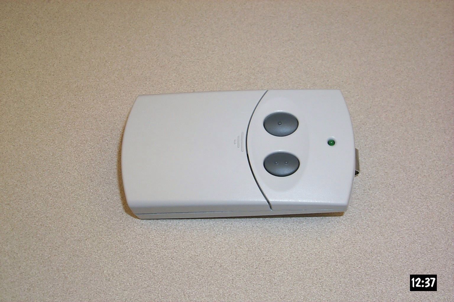
HBW1D1519Garage Door Opener
Chamberlain Group LLC, The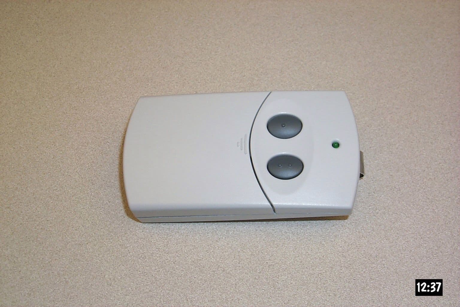
Click to zoom
Application Details
- Equipment Class
- DSC - Part 15 Security/Remote Control Transmitter
- Date of Grant
- Jun 05, 2001
- Application Purpose
- Original Equipment
- Date of Application
- Mar 25, 2001
- Equipment Note
- Garage Door Opener
- Frequency Range
- 390.00000000 - 390.00000000
- Company
- Chamberlain Group LLC, The
- Country
- United States
Documents & Files
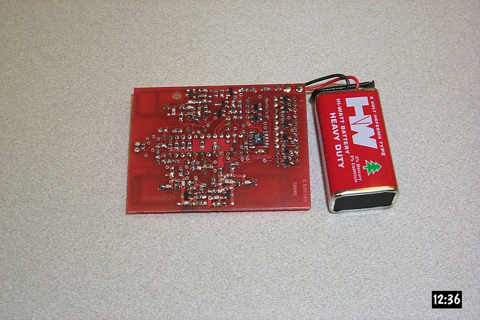
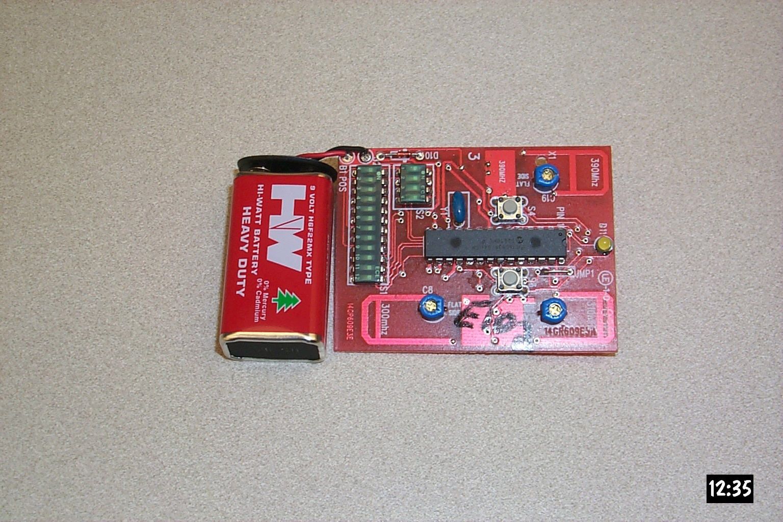
Document Text
Text extracted from the exhibit documents filed with the FCC. Open a document above to read the original.
Cover Letter(s)
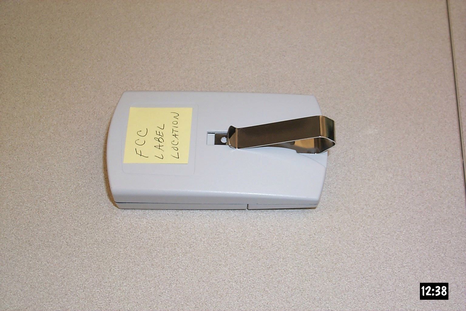
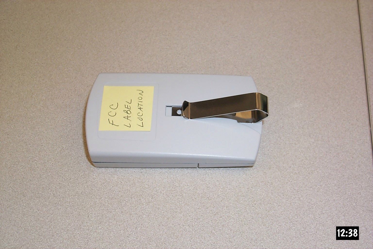
845 Larch Ave. Elmhurst, IL 60126 phone 630.993.6306 fax 630.530.6140 e ma il: b a rb a ra . k e lk ho ff@ c ha mb e rla ingro up . c o m March 26, 2001 Federal Communications Commission EQUIPMENT APPROVAL SERVICES PO Box 358315 Pittsburgh, PA 15251-5315 Re: Request for Certification Enclosed is an application, fee in the amount of $985, and exhibits for Certification of a Remote Control Transmitter Model CLT1 that is manufactured by Chamberlain. The transmitter model referenced in Test Report No. 23566 as CK 1 is identical to Model CLT1. The final instruction sheet is not available at this time, so I have included a typical instruction sheet indicating the FCC statement and important information. The FCC ID of this model, upon certification, will be HBW1D1519. We would appreciate your prompt attention to the submittal. Sincerely, THE CHAMBERLAIN GROUP, INC. Barbara P. Kelkhoff Manager, Product Safety LIST OF EXHIBITS 2 FUNCTION, REMOTE CONTROL TRANSMITTER Model CLT 1 1. Expository Statement 2. Theory of Operation 3. Schematic 4. Photographs 5. FCC Label Drawing 6. Operating Instructions 7. Test Report EXPOSITORY STATEMENT 2 FUNCTION, REMOTE CONTROL TRANSMITTER Model CLT 1 1. Since the final instruction sheet is not available at this time, a typical draft version has been included. The instructions include statements required to assure compliance with the Commission's Rules; Part 15. 2. Labeling is in accordance with the Commission's labeling requirements, Parts 2 and 15, Section 15.19. 3. This transmitter is intended for use with the certified receivers of garage door and gate operator systems manufactured by Chamberlain , Genie , and Linear . 4. The transmitter is equipped with an automatically releasing push-button switch. Transmission is terminated upon release of the push-button. 5. Transmitter Model CLT 1 is factory set to 300, 310, and 390 ± 0.1% MHz.. It is not intended to be readjusted in the field, and specific instructions prohibiting tampering are provided to the user. 6. Test data for Model CLT 1 is part of this submission. No emissions were detected in the forbidden bands below 1.0 GHz. Certified by: Barbara P. Kelkhoff Manager, Product Safety UNIVERSAL TRANSMITTER CIRCUIT DESCRIPTION FOR MODEL CLT 1 (schematic: 195D1519) The Universal Transmitter is a unique combination of circuits which attains compatibility with most garage door openers by means of programmable micro controller with non-volatile memory and three RF colpits oscillators. RF Circuit- Comprises of three RF transmit circuits. Each RF circuit is tuned to a different frequency. Each RF circuit is selected by the programming of U1. Transmit osc one (300mhz) comprises of the following components: C6,C8 C11,C5 and pcb loop make up the tuned circuit.C8 allows you to tune to 300mhz.. C12 provides positive feedback of Q2. R26 R25 and R24 provides DC bias. R32 and R30 provide isolation to the other RF stages. Transmit osc two (310mhz) comprises of the following components: C13,C16 C17,C7 and PCB loop make up the tuned circuit.C13 allows you to tune to 300mhz.. C14 provides positive feedback of Q3. R21 R22 and R23 provides DC bias. R12 and R33 provide isolation to the other RF stages. Transmit osc three (390mhz) comprises of the following components: C19,C20 C21,C24 and PCB loop make up the tuned circuit.C19 allows you to tune to 300mhz.. C14 provides positive feedback of Q5. R27 R28 and R29 provides DC bias. R31 and R35 provide isolation to the other RF stages. Mirco controller - U1 is an 8-bit micro controller which in addition to program memory and RAM also contains a small amount of EEPROM. This combination allows code that is field programmable and non-volatile to be stored in this location. The micro timing is based on an on- board oscillator with an external 4mhz ceramic resonator.The micro controller provides the code output, the frequency logic, the LED drive,and powers to the latch circuit that keeps the power on once a switch(S3 and S4)is pushed for <2sec.If S3 or S4 is held down the latch circuit will stay on for <144sec. Switches,Latch and power supply - The zener diode regulates the micro voltage to +5.1v and allows the voltage to remain in regulation for the useful life of one 9.0v battery source. Q1,Q2,R8,R13,R9,C2,R18,R10 and D9 make up the latch circuit. When S3 or S4 is pushed the latch circuit will stay on for 2sec than pin 24 of u1 will go low. The pushbutton S3 and S4 perform programming and transmit select function (see programming sheet ). S2 provide the selection for what brand transmitter you are programming. S1 is used for certain brands of transmitters witch uses code switches.D1,D2,D3,D4,D5,D6,D7 and D8 allow the micro to scan the switch setting during programming. 1. EXPOSITORY STATEMENT 2. THEORY OF OPERATION 3. SCHEMATIC 4. PHOTOGRAPHS 5. FCC LABEL DRAWING 6. OPERATING INSTRUCTIONS 7. TEST REPORT
Operational Description
Transmitter circuit description Model: CLT1 Schematic: 195d1519 The Universal Transmitter is a unique combination of circuits which attains compatibility with most garage door openers by means of programmable micro controller with non-volatile memory and three RF colpits oscillators. RF Circuit- Comprises of three RF transmit circuits. Each RF circuit is tuned to a different frequency. Each RF circuit is selected by the programming of U1. Transmit osc one (300mhz) comprises of the following components: C6,C8 C11,C5 and pcb loop make up the tuned circuit.C8 allows you to tune to 300mhz.. C12 provides positive feedback of Q2. R26 R25 and R24 provides DC bias. R32 and R30 provide isolation to the other RF stages. Transmit osc two (310mhz) comprises of the following components: C13,C16 C17,C7 and PCB loop make up the tuned circuit.C13 allows you to tune to 300mhz.. C14 provides positive feedback of Q3. R21 R22 and R23 provides DC bias. R12 and R33 provide isolation to the other RF stages. Transmit osc three (390mhz) comprises of the following components: C19,C20 C21,C24 and PCB loop make up the tuned circuit.C19 allows you to tune to 300mhz.. C14 provides positive feedback of Q5. R27 R28 and R29 provides DC bias. R31 and R35 provide isolation to the other RF stages. Mirco controller - U1 is an 8-bit micro controller which in addition to program memory and RAM also contains a small amount of EEPROM. This combination allows code that is field programmable and non-volatile to be stored in this location. The micro timing is based on an on-board oscillator with an external 4mhz ceramic resonator.The micro controller provides the code output, the frequency logic, the LED drive,and powers to the latch circuit that keeps the power on once a switch(S3 and S4)is pushed for <2sec.If S3 or S4 is held down the latch circuit will stay on for <144sec. Switches,Latch and power supply - The zener diode regulates the micro voltage to +5.1v and allows the voltage to remain in regulation for the useful life of one 9.0v battery source. Q1,Q2,R8,R13,R9,C2,R18,R10 and D9 make up the latch circuit. When S3 or S4 is pushed the latch circuit will stay on for 2sec than pin 24 of u1 will go low. The pushbutton S3 and S4 perform programming and transmit select function (see programming sheet ). S2 provide the selection for what brand transmitter you are programming. S1 is used for certain brands of transmitters witch uses code switches.D1,D2,D3,D4,D5,D6,D7 and D8 allow the micro to scan the switch setting during programming.
Schematics
REF-DESPART NUMBERDESCRIPTIONQTY C11030D73300010CAP SMD0805 3.3pF 5% N1501 C1-3030D710422R0CAP SMD0805 0.01uF 20% X7R3 C17 C22030D71820002CAP SMD0805 180pF 5% NPO 50V2 C18030D73000000CAP SMD0805 3.0pF 5% NPO1 C21030D76810000CAP SMD0805 68pF 5% NPO1 C24030D72203000CAP SMD0805 2.2pF +/-.1 NPO1 C4 C12 C14030D71500000CAP SMD0805 1.5pF 5% NPO3 C5 C15 C23 C28030D71020002CAP SMD0805 100pF 5% NPO 50V4 C6 C9-10 C16 C20030D76800000CAP SMD0805 6.8pF 5% NPO5 C7030D73903000CAP SMD0805 3.9pF +/-.1 NPO1 C8 C13 C1930B0431CAPACITOR, VARIABLE TOP ADJ3 D1052A0041DIODE, ZENER 5.1V1 D1152B0079-2DIODE, LED T1 YELLOW1 D1-952B0070DIODE, SMD DUAL COMMON CATHODE9 Q1207C0109TRANSISTOR, SMD PNP SWITCH1 Q2207C0073TRANSISTOR, SMD NPN SWITCH1 Q3-5207C0074TRANSISTOR, SMD NPN RF3 R10 R19311C1025RES SMD0805 1.0K 5%2 R12 R30-33 R35311C1015RES SMD0805 100 5%6 R13311C2235RES SMD0805 22K 5%1 R1-4 R7 R14-18 R20-22 R25-28 R34 311C1035RES SMD0805 10K 5%18 R23311C3325RES SMD0805 3.3K 5%1 R24 R29311C2225RES SMD0805 2.2K 5%2 R5 R11311C4715RES SMD0805 470 5%2 R6311C4725RES SMD0805 4.7K 5%1 R8-9311C1045RES SMD0805 100K 5%2 S1180B0208SWITCH DIP 12PST SLIDE1 S2180B0174SWITCH DIP 4PST SLIDE1 S3-4180B0120-2SWITCH, MOMENTARY PB2 U1127A0007SOIC MICROCHIP CLICKER1 U2125C0273SOIC, SERIAL EEPROM 24LC01B1 Y133B0039RESONATOR, CERAMIC 4MHz1 ITEM 1023B0099BATTERY CONNECTOR 9V1 ITEM 2014R0609PCB 4UP 0.25 ITEM 3 184A0086SPACER .100X1871
Schematics
REF-DESPART NUMBERDESCRIPTIONQTY C11030D73300010CAP SMD0805 3.3pF 5% N1501 C1-3030D710422R0CAP SMD0805 0.01uF 20% X7R3 C17 C22030D71820002CAP SMD0805 180pF 5% NPO 50V2 C18030D73000000CAP SMD0805 3.0pF 5% NPO1 C21030D76810000CAP SMD0805 68pF 5% NPO1 C24030D72203000CAP SMD0805 2.2pF +/-.1 NPO1 C4 C12 C14030D71500000CAP SMD0805 1.5pF 5% NPO3 C5 C15 C23 C28030D71020002CAP SMD0805 100pF 5% NPO 50V4 C6 C9-10 C16 C20030D76800000CAP SMD0805 6.8pF 5% NPO5 C7030D73903000CAP SMD0805 3.9pF +/-.1 NPO1 C8 C13 C1930B0431CAPACITOR, VARIABLE TOP ADJ3 D1052A0041DIODE, ZENER 5.1V1 D1152B0079-2DIODE, LED T1 YELLOW1 D1-952B0070DIODE, SMD DUAL COMMON CATHODE9 Q1207C0109TRANSISTOR, SMD PNP SWITCH1 Q2207C0073TRANSISTOR, SMD NPN SWITCH1 Q3-5207C0074TRANSISTOR, SMD NPN RF3 R10 R19311C1025RES SMD0805 1.0K 5%2 R12 R30-33 R35311C1015RES SMD0805 100 5%6 R13311C2235RES SMD0805 22K 5%1 R1-4 R7 R14-18 R20-22 R25-28 R34 311C1035RES SMD0805 10K 5%18 R23311C3325RES SMD0805 3.3K 5%1 R24 R29311C2225RES SMD0805 2.2K 5%2 R5 R11311C4715RES SMD0805 470 5%2 R6311C4725RES SMD0805 4.7K 5%1 R8-9311C1045RES SMD0805 100K 5%2 S1180B0208SWITCH DIP 12PST SLIDE1 S2180B0174SWITCH DIP 4PST SLIDE1 S3-4180B0120-2SWITCH, MOMENTARY PB2 U1127A0007SOIC MICROCHIP CLICKER1 U2125C0273SOIC, SERIAL EEPROM 24LC01B1 Y133B0039RESONATOR, CERAMIC 4MHz1 ITEM 1023B0099BATTERY CONNECTOR 9V1 ITEM 2014R0609PCB 4UP 0.25 ITEM 3 184A0086SPACER .100X1871
Contact Information
Applicant
Thomas DeSilvia(Director Corporate Compliance)
Technical Contact
Chamberlain Group Inc., TheHenry M Sieradzki
[email protected]630-993-6564
845 Larch Avenue · Elmhurst, Illinois · United States
Test Firm
Elite Electronic Engineering Co.Daniel Crowder
Technical Specifications
| # | Rule Parts | Frequency Range | Power Output | Tolerance |
|---|---|---|---|---|
| 3 | 15C | 390 MHz - 390 MHz | - | % |
Other Applications from Chamberlain Group LLC, The

HBW73514
Jul 06, 2026iDock Link 2
Equipment Class
DSS - Part 15 Spread Spectrum TransmitterHBW-VKP2K
Jun 23, 2026SMART GARAGE VIDEO KEYPAD
Equipment Class
DTS - Digital Transmission System
HBWCHM1
Dec 03, 2025Wireless Chime
Equipment Class
DTS - Digital Transmission SystemHBWN519
Oct 10, 2024VEHICULAR GATE OPENER
Equipment Class
DSS - Part 15 Spread Spectrum TransmitterHBWN329
Sep 22, 2024Handheld Remote
Equipment Class
DSC - Part 15 Security/Remote Control Transmitter