HBW1D8075Commercial Door Operator
Chamberlain Group LLC, The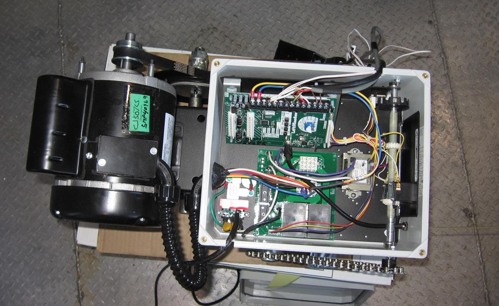
Click to zoom
Application Details
- Equipment Class
- DSS - Part 15 Spread Spectrum Transmitter
- Date of Grant
- Mar 06, 2014
- Application Purpose
- Original Equipment
- Date of Application
- Mar 06, 2014
- Equipment Note
- Commercial Door Operator
- Frequency Range
- 902.25000000 - 926.75000000
- Company
- Chamberlain Group LLC, The
- Country
- United States
Documents & Files
Document Text
Text extracted from the exhibit documents filed with the FCC. Open a document above to read the original.
Users Manual
L3 GT T AND APT H, J, AND HJ GH Serial # Installation Date 2 YEAR WARRANTYTHIS PRODUCT IS TO BE INSTALLED AND SERVICED BY A TRAINED DOOR SYSTEMS TECHNICIAN ONLY. Operators are shipped in C2 operating mode. Visit www.liftmaster.com to locate a professional installing dealer in your area. CONTACT INFORMATION INDUSTRIAL DUTY COMMERCIAL DOOR OPERATOR INSTALLATION MANUAL Security+2.0 TM TABLE OF CONTENTS SAFETY INFORMATION 3 TROLLEY OPERATORS 4-12 Carton Inventory . . . . . . . . . . . . . . . . . . . . . . . . . . . . . . . 4 Operator Specifications . . . . . . . . . . . . . . . . . . . . . . . . . 4-5 Maximum Door Area . . . . . . . . . . . . . . . . . . . . . . . . . . . . 5 Weights and Dimensions . . . . . . . . . . . . . . . . . . . . . . . . . 6 ASSEMBLY. . . . . . . . . . . . . . . . . . . . . . . . . . . . . . . . . . .7-9 Assemble the Operator (Models T and GT) . . . . . . . . . 7 Install the Chain (Models T and GT) . . . . . . . . . . . . . . 8 Assemble the Operator (Model APT) . . . . . . . . . . . . . . 9 TYPICAL INSTALLATION . . . . . . . . . . . . . . . . . . . . . .10-12 Install the Header Bracket . . . . . . . . . . . . . . . . . . . . . 10 Attach the Track to the Header Bracket . . . . . . . . . . . 11 Hang the Operator . . . . . . . . . . . . . . . . . . . . . . . . . . . 11 Attach the Door Arm . . . . . . . . . . . . . . . . . . . . . . . . . 12 HOIST AND JACKSHAFT OPERATORS 13-17 Carton Inventory . . . . . . . . . . . . . . . . . . . . . . . . . . . . . . 13 Operator Specifications . . . . . . . . . . . . . . . . . . . . . . .13-14 Maximum Door Area . . . . . . . . . . . . . . . . . . . . . . . . . . . 14 Weights and Dimensions . . . . . . . . . . . . . . . . . . . . . . . . 15 ASSEMBLY. . . . . . . . . . . . . . . . . . . . . . . . . . . . . . . . . . . 16 Assemble the Operator . . . . . . . . . . . . . . . . . . . . . . . 16 TYPICAL INSTALLATION. . . . . . . . . . . . . . . . . . . . . .16-17 Determine Mounting Location . . . . . . . . . . . . . . . . . . 16 Mounting . . . . . . . . . . . . . . . . . . . . . . . . . . . . . . . . . . 17 Install the Manual Disconnect . . . . . . . . . . . . . . . . . . 17 WIRING 18-19 Power and Ground . . . . . . . . . . . . . . . . . . . . . . . . . . . . . 18 Motor Power Plug Selection . . . . . . . . . . . . . . . . . . . . . 18 Control Station . . . . . . . . . . . . . . . . . . . . . . . . . . . . . . . . 19 ENTRAPMENT PROTECTION 20-22 LiftMaster Monitored Entrapment Protection (LMEP) . . . . . . . . . . . . . . . . . . . . . . . . . . . . . 20 Install the LMEP’s (Optional) . . . . . . . . . . . . . . . . . . . . . 21 Wire the LiftMaster Monitored Entrapment Protection (LMEP) Devices . . . . . . . . . . . . . . . . . . . . . . 21 ADJUSTMENT 22-23 Limit Adjustment . . . . . . . . . . . . . . . . . . . . . . . . . . . . . . 22 Clutch Adjustment (Belt Drive Model Operators) . . . . . . 23 TESTING 24 MANUAL RELEASE 25-26 Emergency Disconnect System Model GT and T . . . . . . 25 Emergency Disconnect System Model APT . . . . . . . . . . 25 Emergency Disconnect System Model H, GH, J, and HJ . . . . . . . . . . . . . . . . . . . . . . . . . 26 PROGRAMMING 27-34 Introduction to Programming . . . . . . . . . . . . . . . . . . . . 27 Determine and Set Wiring Type . . . . . . . . . . . . . . . . . . . 28 Programming Remote Controls . . . . . . . . . . . . . . . . .29-30 Programming for MyQ ® Devices (Optional) . . . . . . . . . . 31 Maintenance Alert System (MAS) . . . . . . . . . . . . . . . . . 31 Open Mid Stop . . . . . . . . . . . . . . . . . . . . . . . . . . . . . . . . 32 Timer-To-Close . . . . . . . . . . . . . . . . . . . . . . . . . . . . .32-33 Car Dealer Mode . . . . . . . . . . . . . . . . . . . . . . . . . . . . . . 33 Maximum Run Timer (MRT) . . . . . . . . . . . . . . . . . . . . . 34 Resetting Factory Defaults - Clearing Memory. . . . . . . . 34 MAINTENANCE 35 Maintenance Schedule . . . . . . . . . . . . . . . . . . . . . . . . . . 35 Life of Operator Feature (Odometer/Cycle Counter). . . . 35 Brake (If Present). . . . . . . . . . . . . . . . . . . . . . . . . . . . . . 35 How to Order Repair Parts. . . . . . . . . . . . . . . . . . . . . . . 35 TROUBLESHOOTING 36-39 Diagnostic Chart. . . . . . . . . . . . . . . . . . . . . . . . . . . . . . . 36 Troubleshooting Guide. . . . . . . . . . . . . . . . . . . . . . . . . . 37 Troubleshooting Error Codes . . . . . . . . . . . . . . . . . . . . . 38 Troubleshooting Radio Functionality . . . . . . . . . . . . . . . 39 WIRING DIAGRAMS 40-41 Logic 5 Single Phase Wiring Diagram . . . . . . . . . . . . . . 40 Logic 5 Three Phase Wiring Diagram . . . . . . . . . . . . . . 41 ACCESSORIES 42 CONTROL CONNECTION DIAGRAM 43 Table of Contents 2 SAFETY INFORMATION TO REDUCE THE RISK OF SEVERE INJURY OR DEATH: IMPORTANT INSTALLATION INSTRUCTIONS 1. READ AND FOLLOW ALL INSTALLATION WARNINGS AND INSTRUCTIONS. 2. Install door operator ONLY on properly balanced and lubricated door. An improperly balanced door may NOT reverse when required and could result in SEVERE INJURY or DEATH. 3. ALL repairs to cables, spring assemblies and other hardware MUST be made by a trained door systems technician BEFORE installing operator. 4. Disable ALL locks and remove ALL ropes connected to door BEFORE installing operator to avoid entanglement. 5. Install door operator 8 feet (2.44 m) or more above floor. 6. NEVER connect door operator to power source until instructed to do so. 7. NEVER wear watches, rings or loose clothing while installing or servicing operator. They could be caught in door or operator mechanisms. 8. Install control station: • within sight of the door. • out of reach of children at minimum height of 5 feet (1.5 m). • away from ALL moving parts of the door. 9. Install the control station far enough from the door to prevent the user from coming in contact with the door while operating the controls. 10. Install the entrapment warning placard on wall next to the control station in a prominent location that…
Text truncated - open the document above for the full version.
Users Manual
23 ADJUSTMENT CLUTCH ADJUSTMENT (BELT DRIVE MODEL OPERATORS) Remove the cotter pin from the clutch nut on the clutch shaft. Turn the clutch nut to release tension. Re-tighten the clutch nut until there is just enough tension to permit smooth operation of the door and to allow the clutch to slip if the door is obstructed. Secure the clutch nut with the cotter pin. 1 1 2 2 3 3 4 4 1 4 2 3 Adjustment To avoid SERIOUS personal INJURY or DEATH from electrocution: • Disconnect electric power BEFORE performing ANY adjustments or maintenance. ATTENTION AVERTISSEMENT AVERTISSEMENT AVERTISSEMENT WARNING CAUTION WARNING WARNING WARNING PRECAUCIÓN ADVERTENCIA ADVERTENCIA ADVERTENCIA AUXILIARY REVERSAL SYSTEM / RPM SENSOR The Auxiliary Reversal System is designed to protect the door and motorized operator. It is NOT a substitute for an entrapment sensing device. Feature: This feature utilizes the RPM sensor connected to the logic board to detect when the clutch slips and reverses the door (clutch must be properly adjusted). In addition, the RPM eliminates the need for a centrifugal switch on single phase motors. Benefit: The Auxiliary Reversal System reverses the operator upon hitting an obstruction, preventing excessive door and operator damage. UL325 requires the use of monitored entrapment protection devices for primary entrapment protection. By removing the centrifugal switch on single phase motors, the leading cause of motor failures is eliminated. (Auxiliary Reversal System is not applicable on GH models unless the clutch modification is installed.) NOTE: This feature is automatically learned and does not require programming. LOSEOPEN RPM Sensor Logic Board 1 2 3 Loosen set screws on clutch nut. Back off clutch nut until there is very little tension on the clutch spring. Tighten clutch nut gradually until there is just enough tension to permit the operator to move the door smoothly but to allow the clutch to slip if the door is obstructed. When the clutch is properly adjusted, it should generally be possible to stop the door by hand during travel. Loosen set screws of torque adjustment nut on the gear reducer. Back off torque nut until there is very little tension on the belleville washers. Tighten torque nut gradually until there is just enough tension to permit the operator to move the door smoothly through a complete open/close cycle, but to allow the reducer to slip if the door is obstructed. Re-tighten the set screw that is directly over the flat portion of the shaft. (3) Set Screws Set Screws Torque Nut ADJUST TORQUE LIMITER CLUTCH (MODEL GT) MODEL GH (OPTIONAL MODIFICATION) 24 TESTING Testing TEST 3-BUTTON CONTROL STATION 1. Press OPEN button. (The door should move in the open direction.) 2. Press STOP button. (The door should stop.) 3. Press and hold the CLOSE button. (The door should move in the close direction.) 4. Release CLOSE button. Door should stop if in C2 or D1 mode. Door will reverse to full open position in E2 mode. The door should continue closing in all other modes. 5. Press STOP button. (The door should stop.) TEST LIMIT ADJUSTMENT 1. Press OPEN button. (The door should open.) 2. Allow the door to fully open. 3. Press and hold the CLOSE button. (The door should close.) 4. Allow the door to fully close. 5. If the limits are not set properly, remove power and adjust limits (refer to Limit Adjustment section). TEST PHOTOELECTRIC SENSORS (IF APPLICABLE) 1. Open the door. 2. Place an obstruction in the path of the photoelectric sensors. The LMEP LED will blink on the logic board. 3. Press and hold the CLOSE button. The door should not close. 4. Remove the obstruction. 5. Press and hold the CLOSE button. Door should close. If the LMEP is activated while closing the door should reverse. TEST EDGE SENSORS (IF APPLICABLE) 1. Open door. 2. Place an obstruction in the path of the door. 3. Press and hold the CLOSE button. The door should stop and/or reverse. 4. Remove obstruction and hold the CLOSE button. Door should fully close. NOTE: The Logic 5 control board will automatically learn the LMEP device once it is properly connected. If the LMEP device is misaligned, activated, or disconnected the LMEP LED on the logic control board will blink on and off. You can close the door by entering the Restricted Close (RC) mode by holding the close button. The operator will begin closing after 5 seconds and will continue to close to the Close Limit or when the close button is released. To unlearn the LMEP device, turn the selector dial to DIAG, push and hold the stop button until the MAS LED flashes. Without the LMEP device connected the only mode of operation will be B2, D1 or E2. IMPORTANT NOTES: • Be sure you have read and understand all safety instructions included in this manual. • Be sure the owner or person(s) responsible for operation of the door have read and understand the safety instructions, know how to electrically operate the door in a safe manner and how to manually disconnect the door from the operator. TESTING To avoid SERIOUS personal INJURY or DEATH: • Disconnect electric power BEFORE performing ANY adjustments or maintenance. • ALL maintenance MUST be performed by a trained door systems technician. ATTENTION AVERTISSEMENT AVERTISSEMENT AVERTISSEMENT WARNING CAUTION WARNING WARNING WARNING PRECAUCIÓN ADVERTENCIA ADVERTENCIA ADVERTENCIA Apply power to the operator. When power is applied to the operator, the following LED’s will illuminate: STOP, CLOSE, OPEN, LMEP, 24Vac, RADIO, DATA, TIMER ENABLE, OLS MID, SLS, CLS, and MAS. Once the power up process is completed (approximately 2-3 seconds) only the appropriate LED’s will continue to be lit: • Between limits: 24Vac and STOP • Fully closed position: 24Vac, STOP, CLS and SLS • Fully opened position: 24Vac, STOP and OLS Additional LED’s will light when device(s) are activated. NOTE: When the power up process is over, the MAS LED will blink a code indicating the version of firmware. If the selector dial is in the DIAG, OPTN, or P…
Text truncated - open the document above for the full version.
Cover Letter(s)
845 Larch Ave. Elmhurst, IL 60126 Phone 630.993.6306 Fax 630.516.6863 Email: [email protected] February 5, 2014 Federal Communication Commission Equipment Authorization Division Application Processing Branch 7435 Oakland Mills Road Columbia, Maryland 21046 FCC ID: HBW1D8075 for circuit assembly 1D8075-1 Request for Confidentiality In accordance with 47 C.F.R. Section 0.457 and 0.459, we, Chamberlain Group, Inc., hereby request confidentiality for the block diagram, schematic and product description presented for certification. In support of the Request for Confidentiality, the following is stated: Enclosed within this application is technical information which we deem to be trade secrets and proprietary. If made public, the information might be used to our disadvantage. To assist in assuring that we receive the full value of our product and protect its competitive posture, we respectfully request this grant of confidentiality. I would appreciate your prompt attention to the submittal. If there are any questions, please call me at 630-993-6306 or send a fax to 630-516- 6863. Sincerely, Barbara Kelkhoff Regulatory Project Manager II Chamberlain Group, Inc. 845 Larch Ave. Elmhurst, IL. 60126
Cover Letter(s)
845 Larch Ave. Elmhurst, IL 60126 Phone 630.993.6306 Fax 630.516.6863 Email: [email protected] February 5, 2014 Federal Communication Commission Equipment Authorization Division Application Processing Branch 7435 Oakland Mills Road Columbia, Maryland 21046 c.c. UL LLC. 333 Pfingsten Road Northbrook, IL 60062 To whom it may concern: I, the undersigned, hereby authorize Bart Mucha, of UL LLC, to act on our behalf in all manners relating to application for equipment authorization, including signing of all documents relating to these matters. Any and all acts carried out by Bart Mucha of UL on our behalf, shall have the same effect as acts of our own. I, the undersigned, hereby certify that we are not subject to a denial of federal benefits, that includes FCC benefits, pursuant to Section 5301 of the Anti-Drug Abuse Act of 1988, 21 U.S.C. 853(a). In authorizing UL as our agent, we still recognize that we are responsible to: a) Comply with the relevant provisions of the certification program; b) Make all necessary arrangements for the conduct of the evaluation, including provision for Examining documentation and access to all areas, records (including internal audit reports) And personnel for the purposes of evaluation (e.g. testing, inspection, assessment, surveillance, reassessment) and resolution of complaints; c) Make claims regarding certification only in respect of the scope for which certification has been granted; d) Do not use our product certification in such a manner as to bring the Certification Division Into disrepute and not make any statement regarding our product certification which the Certification Division may consider misleading or unauthorized; e) Upon suspension or cancellation of certification, discontinue use of all advertising matter That contains any reference thereto and returns any certification documents as required by the Certification Division; f) Use certification only to indicate the products are certified as being in conformity with Specified standards; g) Endeavor to ensure that no certificate or report nor any part thereof is used in a misleading manner; h) Ensure that any reference to our product certification in communication media such as documents, brochures or advertising, complies with the requirements of the Certification Division; i) Keep a record of all complaints made known to the us relating to the product’s compliance with requirements of the relevant standard and to make these records available to the Certification Division when requested; j) Take appropriate action with respect to such complaints and any deficiencies found in products or services that affect compliance with the requirements for certification; k) Document the actions taken. This authorization is valid until further written notice from the applicant. Yours sincerely, Barbara Kelkhoff Regulatory Project Manager II Chamberlain Group, Inc. 845 Larch Ave. Elmhurst, IL. 60126
External Photos
FCC IC: HBW1D8075 FCC IC: HBW1D8075 FCC IC: HBW1D8075
ID Label/Location Info
FCC ID: HBW1D8075 PBA Tracking no: 583246
Internal Photos
FCC ID: HBW1D8075 Internal Photos FCC ID: HBW1D8075 Internal Photos FCC ID: HBW1D8075 Internal Photos FCC ID: HBW1D8075 Internal Photos
RF Exposure Info
MPE Calculation Applicant : Chamberlain Group Type of Equipment : Frequency Hopper Model No. : 1D8075 FCC ID : HBW1D8075 RF Exposure Calculations: FCC 2.1091 The following information provides the minimum separation distance for the highest gain antenna provided with the as calculated from FCC OET Bulletin 65 Appendix A, T able (B) Limits for General Population / Uncontrolled Exposure. This calculation is based on the highest EIRP possible from the system, considering maximum power and antenna gain, and considering a 0.6mW/cm^2 uncontrolled exposure limit. The Friis formula used was: S = (P * G ) / (4* π * r2) Where P = 29.2 mW (Maximum peak output power) G = 0.501 Numerical Antenna gain; equal -3.0 dBi r = 20.0 cm For: HBW6597 S = 0.00291 mW/cm 2
Test Report
UL LLC An organization dedicated 333 Pfingsten Rd. to public safety and committed to Northbrook, IL 60062 quality service for over 100 years Tel: (847) 272-8800 UL LLC 333 Pfingsten Rd. Northbrook, IL 60062 www.ul.com/emc (847) 272-8800 Order Number: 10105496 Date: February 5, 2014 Model: CJ501L5 (PCB Model 1D8075) Electromagnetic Compatibility Test Report For Chamberlain Group Inc. Copyright 2012 UL LLC UL LLC authorizes the above-named company to reproduce this Report provided it is reproduced in its entirety. Order Number: 10105496 Page 2 of 46 Model Number: CJ501L5 (PCB Model 1D8075) Client Name: Chamberlain Group Inc. UL LLC 333 Pfingsten Rd. Northbrook, IL 60062 USA Tel.: 847 272-8800 Rev. No 1.0Rev. No 1.0 EMC Report 2012-87-EM-F0042 Test Report Details Tests Performed By: UL LLC 333 Pfingsten Rd. Northbrook, IL 60062 Tests Performed For: Chamberlain Group Inc. 845 Larch Av Elmhurst, IL 60126 Applicant Contact: Hank Sieradzki Phone: (630) 993-6564 E-mail: [email protected] Test Report Date: February 5, 2014 Product Type: Wireless Device Product standards 47 CFR Part 15, Subpart C, RSS-210, RSS-Gen Model Number: CJ501L5 (PCB Model 1D8075) EUT Category: Wireless Device Testing Start Date: January 7, 2014 Date Testing Complete: January 21, 2014 Overall Results: Compliant UL LLC reports apply only to the specific samples tested under stated test conditions. All samples tested were in good operating condition throughout the entire test program. It is the manufacturer's responsibility to assure that additional production units of this model are manufactured with identical electrical and mechanical components. UL LLC shall have no liability for any deductions, inferences or generalizations drawn by the client or others from UL LLC issued reports. This report must not be used by the client to claim product certification, approval, or endorsement by NVLAP, NIST, any agency of the Federal Government, or any agency of any government. This report may contain test results that are not covered by the NVLAP or A2LA accreditation. The scope of accreditation is limited to the specific tests that are listed on the NVLAP and/or A2LA websites referenced at the end of this report. Order Number: 10105496 Page 3 of 46 Model Number: CJ501L5 (PCB Model 1D8075) Client Name: Chamberlain Group Inc. UL LLC 333 Pfingsten Rd. Northbrook, IL 60062 USA Tel.: 847 272-8800 Rev. No 1.0Rev. No 1.0 EMC Report 2012-87-EM-F0042 Report Directory 1.0 G E N E R A L - Product Description ..................................................................................................................4 1.1 Equipment Description ...................................................................................................................................4 1.2 Device Configuration During Test ..................................................................................................................4 1.2.1 Equipment Used During Test: ....................................................................................................................4 1.2.2 Input/Output Ports: .....................................................................................................................................4 1.2.3 Power Interface: .........................................................................................................................................5 1.3 EUT Configurations ........................................................................................................................................5 1.4 EUT Operation Modes ....................................................................................................................................5 1.5 Rational for EUT Configuration ......................................................................................................................5 2.0 Summary ............................................................................................................................................................5 2.1 Deviations from standard test methods ..........................................................................................................5 2.2 Device Modifications Necessary for Compliance ...........................................................................................5 2.3 Reference Standards .....................................................................................................................................6 2.4 Results Summary ...........................................................................................................................................7 3.0 Calibration of Equipment Used for Measurement ..............................................................................................8 4.0 EMISSIONS TEST RESULTS ............................................................................................................................8 4.1 Test Conditions and Results – MAINS TERMINAL – CONDUCTED EMISSIONS .......................................9 4.2 Test Conditions and Results – DIGITAL RADIATED EMISSIONS ............................................................. 14 4.3 Test Conditions and Results – SPURIOUS EMISSIONS (Antenna Conducted and Radiated) ................. 17 4.4 Test Conditions and Results – MAXIMUM PEAK OUTPUT POWER ........................................................ 32 4.5 Test Conditions and Results – Dwell Time and Duty Cycle Correction ...................................................... 34 4.6 Test Conditions and Results – NUMBER OF HOPPING FREQUENCIES ................................................. 36 4.7 Test Conditions and Results – 20DB BANDWIDTH & 99% BANDWIDTH ................................................. 38 4.8 Test Conditions and Results – Carrier Frequency Separation .................................................................... 40 Appendix A ..................................................…
Text truncated - open the document above for the full version.
Test Setup Photos
Order Number: 10105496 Page 43 of 46 Model Number: CJ501L5 (PCB Model 1D8075) Client Name: Chamberlain Group Inc. UL LLC 333 Pfingsten Rd. Northbrook, IL 60062 USA Tel.: 847 272-8800 Rev. No 1.0Rev. No 1.0 EMC Report 2012-87-EM-F0042 Appendix A Test Setup Photos Line Conducted Emissions Antenna Port Emissions Radiated Spurious Emissions above below 1GHz Radiated Spurious Emissions above 1GHz
Contact Information
Applicant
Thomas DeSilvia(Director Corporate Compliance)
Test Firm
UL LLCRick Titus
Technical Specifications
| # | Rule Parts | Frequency Range | Power Output |
|---|---|---|---|
| 1 | 15C | 902.25 MHz - 926.75 MHz | 29.00 mW |
Other Applications from Chamberlain Group LLC, The

HBW73514
Jul 06, 2026iDock Link 2
Equipment Class
DSS - Part 15 Spread Spectrum TransmitterHBW-VKP2K
Jun 23, 2026SMART GARAGE VIDEO KEYPAD
Equipment Class
DTS - Digital Transmission System
HBWCHM1
Dec 03, 2025Wireless Chime
Equipment Class
DTS - Digital Transmission SystemHBWN519
Oct 10, 2024VEHICULAR GATE OPENER
Equipment Class
DSS - Part 15 Spread Spectrum TransmitterHBWN329
Sep 22, 2024Handheld Remote
Equipment Class
DSC - Part 15 Security/Remote Control Transmitter