HBW1D8088-1MyQ - Garage Door Controller
Chamberlain Group LLC, The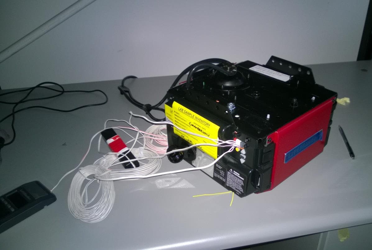
Click to zoom
Application Details
- Equipment Class
- DSS - Part 15 Spread Spectrum Transmitter
- Date of Grant
- Jul 31, 2014
- Application Purpose
- Original Equipment
- Date of Application
- Jul 31, 2014
- Equipment Note
- MyQ - Garage Door Controller
- Frequency Range
- 902.25000000 - 926.75000000
- Company
- Chamberlain Group LLC, The
- Country
- United States
Documents & Files
Document Text
Text extracted from the exhibit documents filed with the FCC. Open a document above to read the original.
Users Manual
CONTENTS Preparation . . . . . . . . . . . . . . . .1-4 Assembly . . . . . . . . . . . . . . . . .5-8 Installation . . . . . . . . . . . . . . . 9-26 Adjustments . . . . . . . . . . . . . 27-29 Battery Backup. . . . . . . . . . . . . . 30 Operation . . . . . . . . . . . . . . . 31-36 Maintenance . . . . . . . . . . . . . 36-37 Troubleshooting. . . . . . . . . . . . . 37 Accessories. . . . . . . . . . . . . . . . 38 Warranty. . . . . . . . . . . . . . . . . . 39 Wi-Fi Belt Drive Garage Door Opener with Battery Backup The Chamberlain Group, Inc. 845 Larch Avenue Elmhurst, Illinois 60126-1196 ■ Please read this manual and the enclosed safety materials carefully! ■ Fasten the manual near the garage door after installation. ■ The door WILL NOT CLOSE unless the Protector System ® is connected and properly aligned. ■ Periodic checks of the garage door opener are required to ensure safe operation. ■ The model number label is located on the left side panel of your garage door opener. ■ This garage door opener is compatible with MyQ ® and Security✚ 2.0™ accessories. ■ DO NOT enable the Timer-to-Close or Wi-Fi ® if you are installing the garage door opener on a one-piece door. The Timer-to-Close and Wi-Fi ® are to be used ONLY with sectional doors. www.chamberlain.com Model Number: Serial Number: Date of Purchase: Models • LW9000WF • HD950WF • WD1000WF FOR RESIDENTIAL USE ONLY Write down the following information for future reference: . . 1 Safety Symbol and Signal Word Review This garage door opener has been designed and tested to offer safe service provided it is installed, operated, maintained and tested in strict accordance with the instructions and warnings contained in this manual. When you see these Safety Symbols and Signal Words on the following pages, they will alert you to the possibility ofserious injury ordeathif you do not comply with the warnings that accompany them. The hazard may come from something mechanical or from electric shock. Read the warnings carefully. Mechanical Electrical When you see this Signal Word on the following pages, it will alert you to the possibility of damage to your garage door and/or the garage door opener if you do not comply with the cautionary statements that accompany it. Read them carefully. Check the Door To prevent possible SERIOUS INJURY or DEATH: l ALWAYS call a trained door systems technician if garage door binds, sticks, or is out of balance. An unbalanced garage door may NOT reverse when required. l NEVER try to loosen, move or adjust garage door, door springs, cables, pulleys, brackets or their hardware, ALL of which are under EXTREME tension. l Disable ALL locks and remove ALL ropes connected to garage door BEFORE installation and operating garage door opener to avoid entanglement. l DO NOT enable Wi-Fi if operating either one-piece or swinging doors. To be enabled ONLY on a sectional door. To prevent damage to garage door and opener: l ALWAYS disable locks BEFORE installing and operating the opener. l ONLY operate garage door opener at 120 V, 60 Hz to avoid malfunction and damage. Before you begin: 1. Disable locks and remove any ropes connected to the garage door. 2. Lift the door halfway up. Release the door. If balanced, it should stay in place, supported entirely by its springs. 3. Raise and lower the door to check for binding or sticking. If your door binds, sticks, or is out of balance, call a trained door systems technician. 4. Check the seal on the bottom of the door. Any gap between the floor and the bottom of the door must not exceed 1/4 inch (6 mm). Otherwise, the safety reversal system may not work properly. 5. The opener should be installed above the center of the door. If there is a torsion spring or center bearing plate in the way of the header bracket, it may be installed within 4 feet (1.2 m) to the left or right of the door center. See page 10. Torsion Spring Extension Spring OR Preparation 2 Test the Wi-Fi ® Signal Strength in your garage Make sure your mobile device is connected to your home network. Stand where your garage door opener will be installed. Check the Wi-Fi signal strength on your mobile device. Go to www.chamberlain.com/wifi to learn more. You’re all set! Install your new garage door opener . Wi-Fi signal is weak or no signal. You may want to: • Buy a Wi-Fi extender • Buy a Chamberlain Internet Gateway • Go to www.chamberlain.com/wifi to learn more Signal Strength: = = = = Additional Items You May Need: Survey your garage area to see if you will need any of the following items: l (2) 2X4 Pieces of wood - May be used to fasten the header bracket to the structural supports. Also used to position the garage door opener during installation and for testing the safety reversing sensors. l Support bracket and fastening hardware - Must be used if you have a finished ceiling in your garage. l Extension brackets (MODEL 041A5281-1) or wood blocks - Depending upon garage construction, extension brackets or wood blocks may be needed to install the safety reversing sensor. l Fastening hardware - Alternate floor mounting of the safety reversing sensor will require hardware not provided. l Outside quick release (MODEL 7702CB) - Required for a garage with NO access door. l Door reinforcement- Required if you have a lightweight steel, aluminum, fiberglass or glass panel door. l Rail extension kit- Required if your garage door is more than 7 feet (2.13 m) high. Tools Needed 3/16 7/16 1/2 5/32 5/16 5/8 9/16 1/4 7/16 Preparation 3 Carton Inventory Your garage door opener is packaged in one carton which contains the motor unit and all parts illustrated below. Accessories vary depending on the garage door opener model purchased. Depending on your model, other accessories may be included with your garage door opener. Instructions for these accessories will be attached to the accessory and are not included in this manual. Save the carton and packing material until the installation and adjustment is complete. The images throughout th…
Text truncated - open the document above for the full version.
Cover Letter(s)
845 Larch Ave. Elmhurst, IL 60126 Phone 630.993.6306 Fax 630.516.6863 Email: [email protected] July 16, 2014 Federal Communication Commission Equipment Authorization Division Application Processing Branch 7435 Oakland Mills Road Columbia, Maryland 21046 c.c. UL LLC. 333 Pfingsten Road Northbrook, IL 60062 To whom it may concern: I, the undersigned, hereby authorize Bart Mucha, of UL LLC, to act on our behalf in all manners relating to application for equipment authorization, including signing of all documents relating to these matters. Any and all acts carried out by Bart Mucha of UL on our behalf, shall have the same effect as acts of our own. I, the undersigned, hereby certify that we are not subject to a denial of federal benefits, that includes FCC benefits, pursuant to Section 5301 of the Anti-Drug Abuse Act of 1988, 21 U.S.C. 853(a). In authorizing UL as our agent, we still recognize that we are responsible to: a) Comply with the relevant provisions of the certification program; b) Make all necessary arrangements for the conduct of the evaluation, including provision for Examining documentation and access to all areas, records (including internal audit reports) And personnel for the purposes of evaluation (e.g. testing, inspection, assessment, surveillance, reassessment) and resolution of complaints; c) Make claims regarding certification only in respect of the scope for which certification has been granted; d) Do not use our product certification in such a manner as to bring the Certification Division Into disrepute and not make any statement regarding our product certification which the Certification Division may consider misleading or unauthorized; e) Upon suspension or cancellation of certification, discontinue use of all advertising matter That contains any reference thereto and returns any certification documents as required by the Certification Division; f) Use certification only to indicate the products are certified as being in conformity with Specified standards; g) Endeavor to ensure that no certificate or report nor any part thereof is used in a misleading manner; h) Ensure that any reference to our product certification in communication media such as documents, brochures or advertising, complies with the requirements of the Certification Division; i) Keep a record of all complaints made known to the us relating to the product’s compliance with requirements of the relevant standard and to make these records available to the Certification Division when requested; j) Take appropriate action with respect to such complaints and any deficiencies found in products or services that affect compliance with the requirements for certification; k) Document the actions taken. This authorization is valid until further written notice from the applicant. Yours sincerely, Barbara Kelkhoff Regulatory Project Manager II Chamberlain Group, Inc. 845 Larch Ave. Elmhurst, IL. 60126
Cover Letter(s)
845 Larch Ave. Elmhurst, IL 60126 Phone 630.993.6306 Fax 630.516.6863 Email: [email protected] July 16, 2014 Federal Communication Commission Equipment Authorization Division Application Processing Branch 7435 Oakland Mills Road Columbia, Maryland 21046 FCC ID: HBW1D8088-1 for circuit assembly 1D8088-1 Request for Confidentiality In accordance with 47 C.F.R. Section 0.457 and 0.459, we, Chamberlain Group, Inc., hereby request confidentiality for the block diagram, schematic and product description presented for certification. In support of the Request for Confidentiality, the following is stated: Enclosed within this application is technical information which we deem to be trade secrets and proprietary. If made public, the information might be used to our disadvantage. To assist in assuring that we receive the full value of our product and protect its competitive posture, we respectfully request this grant of confidentiality. I would appreciate your prompt attention to the submittal. If there are any questions, please call me at 630-993-6306 or send a fax to 630-516- 6863. Sincerely, Barbara Kelkhoff Regulatory Project Manager II Chamberlain Group, Inc. 845 Larch Ave. Elmhurst, IL. 60126
External Photos
FCC ID: HBW1D8088-1 FCC ID: HBW1D8088-1
Internal Photos
FCC ID: HBW1D8088-1 FCC ID: HBW1D8088-1
RF Exposure Info
MPE Calculation Applicant : Chamberlain Group Type of Equipment : Frequency Hopper Model No. : 821LM FCC ID : HBW1D7991 RF Exposure Calculations: FCC 2.1091 The following information provides the minimum separation distance for the highest gain antenna provided with the as calculated from FCC OET Bulletin 65 Appendix A, T able (B) Limits for General Population / Uncontrolled Exposure. This calculation is based on the highest EIRP possible from the system, considering maximum power and antenna gain, and considering a 0.6mW/cm^2 uncontrolled exposure limit. The Friis formula used was: S = (P * G ) / (4* π * r2) Where P = 16.285mW (Maximum peak output power) G = 0.63 Numerical Antenna gain; equal -2 dBi r = 20.0 cm For: HBW1D8088-1 S = 0.00204 mW/cm2 Calculated Power Density for WiFi Module: (FCC ID: COFWMNBM11) The following information provides the minimum separation distance for the highest gain antenna provided with the as calculated from FCC OET Bulletin 65 Appendix A, T able (B) Limits for General Population / Uncontrolled Exposure. This calculation is based on the highest EIRP possible from the system, considering maximum power and antenna gain, and considering a 1.0mW/cm^2 uncontrolled exposure limit. The Friis formula used was: S = (P * G ) / (4* π * r2) Where P = 237mW (Maximum peak output power) G = 0.631 Numerical Antenna gain; equal -2 dBi r = 20.0 cm For: WiFi Module S = 0.595 mW/cm2 Calculated Power Density for BT Module: (FCC ID: COFBMGPBR65) The following information provides the minimum separation distance for the highest gain antenna provided with the as calculated from FCC OET Bulletin 65 Appendix A, T able (B) Limits for General Population / Uncontrolled Exposure. This calculation is based on the highest EIRP possible from the system, considering maximum power and antenna gain, and considering a 1.0mW/cm^2 uncontrolled exposure limit. The Friis formula used was: S = (P * G ) / (4* π * r2) Where P = 5mW (Maximum peak output power) G = 0.562 Numerical Antenna gain; equal -2.5 dBi r = 20.0 cm For: BT Module S = 0.0112 mW/cm2 Calculated Ratio for all transmitters: 0.00204 / 0.6 + 0.595 / 1 + 0.0112 / 1 = 0.609 The total radio for all transmitters under 15.247 is 0.60654 which is less than 1 therefore it is compliant.
Test Report
UL LLC An organization dedicated 333 Pfingsten Rd. to public safety and committed to Northbrook, IL 60062 quality service for over 100 years Tel: (847) 272-8800 UL LLC 333 Pfingsten Rd. Northbrook, IL 60062 www.ul.com/emc (847) 272-8800 Order Number: 10338209 Date: June 26, 2014 Model: 001D8088-1 Electromagnetic Compatibility Test Report For Chamberlain Group Inc. Copyright 2012 UL LLC UL LLC authorizes the above-named company to reproduce this Report provided it is reproduced in its entirety. Order Number: 10338209 Page 2 of 47 Model Number: 001D8088-1 Client Name: Chamberlain Group Inc. UL LLC 333 Pfingsten Rd. Northbrook, IL 60062 USA Tel.: 847 272-8800 Rev. No 1.0Rev. No 1.0 EMC Report 2012-87-EM-F0042 Test Report Details Tests Performed By: UL LLC 333 Pfingsten Rd. Northbrook, IL 60062 Tests Performed For: Chamberlain Group Inc. 845 Larch Av Elmhurst, IL 60126 Applicant Contact: Hank Sieradzki Phone: (630) 993-6564 E-mail: [email protected] Test Report Date: June 26, 2014 Product Type: GDO with 900MHz FHSS Transceiver and 2.4GHz WiFi Module Product standards 47 CFR Part 15, Subpart C, RSS-210, RSS-Gen Model Number: 001D8088 EUT Category: Wireless Device Testing Start Date: May 21, 2014 Date Testing Complete: June 24, 2014 Overall Results: Compliant UL LLC reports apply only to the specific samples tested under stated test conditions. All samples tested were in good operating condition throughout the entire test program. It is the manufacturer's responsibility to assure that additional production units of this model are manufactured with identical electrical and mechanical components. UL LLC shall have no liability for any deductions, inferences or generalizations drawn by the client or others from UL LLC issued reports. This report must not be used by the client to claim product certification, approval, or endorsement by NVLAP, NIST, any agency of the Federal Government, or any agency of any government. This report may contain test results that are not covered by the NVLAP or A2LA accreditation. The scope of accreditation is limited to the specific tests that are listed on the NVLAP and/or A2LA websites referenced at the end of this report. Order Number: 10338209 Page 3 of 47 Model Number: 001D8088-1 Client Name: Chamberlain Group Inc. UL LLC 333 Pfingsten Rd. Northbrook, IL 60062 USA Tel.: 847 272-8800 Rev. No 1.0Rev. No 1.0 EMC Report 2012-87-EM-F0042 Report Directory 1.0 G E N E R A L - Product Description ..................................................................................................................4 1.1 Equipment Description ...................................................................................................................................4 1.2 Device Configuration During Test ..................................................................................................................4 1.2.1 Equipment Used During Test: ....................................................................................................................4 1.2.2 Input/Output Ports: .....................................................................................................................................4 1.2.3 Power Interface: .........................................................................................................................................5 1.3 EUT Configurations ........................................................................................................................................5 1.4 EUT Operation Modes ....................................................................................................................................5 1.5 Rational for EUT Configuration ......................................................................................................................5 2.0 Summary ............................................................................................................................................................5 2.1 Deviations from standard test methods ..........................................................................................................5 2.2 Device Modifications Necessary for Compliance ...........................................................................................5 2.3 Reference Standards .....................................................................................................................................6 2.4 Results Summary ...........................................................................................................................................7 3.0 Calibration of Equipment Used for Measurement ..............................................................................................8 4.0 EMISSIONS TEST RESULTS ............................................................................................................................8 4.1 Test Conditions and Results – MAINS TERMINAL – CONDUCTED EMISSIONS .......................................9 4.2 Test Conditions and Results – DIGITAL RADIATED EMISSIONS ............................................................. 12 4.3 Test Conditions and Results – SPURIOUS EMISSIONS (Antenna Conducted and Radiated) ................. 15 4.4 Test Conditions and Results – MAXIMUM PEAK OUTPUT POWER ........................................................ 31 4.5 Test Conditions and Results – Dwell Time and Duty Cycle Correction ...................................................... 33 4.6 Test Conditions and Results – NUMBER OF HOPPING FREQUENCIES ................................................. 35 4.7 Test Conditions and Results – 20DB BANDWIDTH & 99% BANDWIDTH ................................................. 37 4.8 Test Conditions and Results – Carrier Frequency Separation .................................................................... 40 Appendix A ........................................................................................…
Text truncated - open the document above for the full version.
Test Setup Photos
Order Number: 10338209 Page 44 of 47 Model Number: 001D8088-1 Client Name: Chamberlain Group Inc. UL LLC 333 Pfingsten Rd. Northbrook, IL 60062 USA Tel.: 847 272-8800 Rev. No 1.0Rev. No 1.0 EMC Report 2012-87-EM-F0042 Appendix A Test Setup Photos Line Conducted Emissions Antenna Port Emissions Radiated Spurious Emissions above below 1GHz Radiated Spurious Emissions above 1GHz
Contact Information
Applicant
Thomas DeSilvia(Director Corporate Compliance)
Test Firm
UL LLCRick Titus
Technical Specifications
| # | Rule Parts | Frequency Range | Power Output |
|---|---|---|---|
| 1 | 15C | 902.25 MHz - 926.75 MHz | 16.30 mW |
Other Applications from Chamberlain Group LLC, The

HBW73514
Jul 06, 2026iDock Link 2
Equipment Class
DSS - Part 15 Spread Spectrum TransmitterHBW-VKP2K
Jun 23, 2026SMART GARAGE VIDEO KEYPAD
Equipment Class
DTS - Digital Transmission System
HBWCHM1
Dec 03, 2025Wireless Chime
Equipment Class
DTS - Digital Transmission SystemHBWN519
Oct 10, 2024VEHICULAR GATE OPENER
Equipment Class
DSS - Part 15 Spread Spectrum TransmitterHBWN329
Sep 22, 2024Handheld Remote
Equipment Class
DSC - Part 15 Security/Remote Control Transmitter