HBW2C510Garage Door Monitor (Transmitter)
Chamberlain Group LLC, The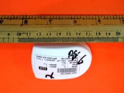
Click to zoom
Application Details
- Equipment Class
- DSC - Part 15 Security/Remote Control Transmitter
- Date of Grant
- Jun 18, 2002
- Application Purpose
- Original Equipment
- Date of Application
- Jun 18, 2002
- Equipment Note
- Garage Door Monitor (Transmitter)
- Frequency Range
- 312.00000000 - 312.00000000
- Company
- Chamberlain Group LLC, The
- Country
- United States
Documents & Files
Document Text
Text extracted from the exhibit documents filed with the FCC. Open a document above to read the original.
Users Manual
CLOSED OPEN Indoor Receiver AC Adapter Transmitter CR2032 3 VOLTS Lithium Battery (CR2032 type)Double-Sided Velcro To prevent possible SERIOUS INJURY or DEATH from a closing garage door: • Activate door ONLY when it can be seen clearly, is properly adjusted, and there are no obstructions to door travel. • ALWAYS keep garage door in sight until completely closed. NEVER permit anyone to cross path of closing garage door. WARNING CAUTION WARNING WARNING OPEN DOOR MONITOR SYSTEM PRE-INSTALLATION SYSTEM TEST 1. The transmitter and receiver are pre-matched (programmed) at the factory. Test the system by flipping the transmitter over while it is a few feet away from the receiver. The receiver will show a green light for closed when the transmitter is face up in the vertical position with the round endof the case pointing down (Figure 1). The red light will flash when the transmitter is face down in the horizontal position (Figure 2). 2. If the green or the red receiver lights do not come on, or do not react as described, see the Troubleshooting or Learning section of these instructions. Know when your garage door is open or closed ! Thank you for purchasing the Craftsman Open Door Monitor. Monitor the status of your garage door from inside your home. No longer will you have to run downstairs or go outside just to see if you or your children have left the garage door open. INSTALLING THE BATTERY IN THE OPEN DOOR INDICATOR TRANSMITTER 1.Place the screw driver blade onthe tab at the end of the case and gently press down and in toward the case. 2. Insert the the lithium battery into the battery clip with the + (positive) side face up. 3. Push the case back together tightly by inserting the top hooks into the back cover, then snap shut the bottom of the case. NOTE:It is normal to hear a rattle from the tilt switch in the Transmitter when tilted or rotated to another position. INDOOR RECEIVER SETUP 1. Plug the AC adapter into any standard 110 volt AC electrical wall outlet and the small plug into the back of the Indoor Receiver. 2. The Receiver has a 9 " antenna wire which comes out the back. The antenna should be straight and not touching metal. 3 V O L T S C L O S E D O P E N Antenna Learn Button AC Adapter Location Figure 1Figure 2 Inside of Garage Double-Sided Velcro Round End Down MOUNTING THE TRANSMITTER Attach the transmitter to the inside of the garage door using the double-sided velcro. Mount the transmitter near the top of the garage door for best results. The round end of the case should be pointing down when the garage door is closed. Open Door Monitor Model 139.53696 ®
Cover Letter(s)
From:Wilson Loke ITS/ES-HKG Sent:Friday, June 14, 2002 5:52 AM To:Roland Gubisch ITS/ES-Box Cc:Danielle Gravelle ITS/ES-Box Subject: RE: TCB Status Dear Roland, I'm sorry on the old user manual. During our test, we found that the EUT had not complied this requirement. I had informed our client to make the modification to disable this function. Therefore, the final tested sample had been disabled this feature. But we do not aware to inform the applicant to delete this feature shown in the manual. Finally, we have requested our client to delete all the information related this feature. The updated user manual is attached for your reference. If you have any queries, please feel free to contact me. Best Regards, Wilson Loke Pager: (852)77713620 Tel: (852) 2173-8575 Fax: (852) 3403-2414 To:Wilson Loke ITS/ES-HKG Subject: Chamberlain 312 MHz Periodic Transmitter FCC ID: HBW2C510 Dear Wilson: The transmitter also routinely polls the receiver, according to the NOTE in the user manual: "The transmitter updates the receiver by transmitting an open or closed signal every few minutes." This automatic polling is permitted under 15.231(a)(3) for security or safety applications, but the duration and frequency of polling are limited to one second duration (the transmitter fails, the duration is > 4 sec) and no more than once per hour (the transmitter fails, it transmits "every few minutes"). There are few alternatives for a device of this type, short of using another Part 15 frequency band where continuous transmission is permitted. Your comments and suggestions are welcome. Regards, Roland
External Photos
Test SetupFCCID : HBW2C510 External Photo -front External Photo - rear
Internal Photos
Test SetupFCCID : HBW2C510 Internal Photo - 1 Internal Photo - 2 Test SetupFCCID : HBW2C510 Internal Photo - 3 Internal Photo – 4
Test Report
• The test results reported in this test report shall refer only to the sample actually tested and shall not refer or be deemed to refer to bulk from which such a sample may be said to have been obtained. • This report shall not be reproduced except in full without prior authorization from Intertek Testing Services Hong Kong Limited. • For Terms And Conditions of the services, it can be provided upon request. Intertek Testing Services Hong Kong Ltd. 2/F., Garment Centre, 576 Castle Peak Road, Kowloon, Hong Kong. Tel: (852) 2173 8888 Fax: (852) 2785 5487 The Chamberlain Group Inc. Application For Certification (FCC ID: HBW2C510) Transmitter WO# 0204180 WL/Sandy May 23, 2002 INTERTEK TESTING SERVICES FCC ID: HBW2C510 i LIST OF EXHIBITS INTRODUCTION EXHIBIT 1:General Description EXHIBIT 2:System Test Configuration EXHIBIT 3:Emission Results EXHIBIT 4:Equipment Photographs EXHIBIT 5:Product Labelling EXHIBIT 6:Technical Specifications EXHIBIT 7:Instruction Manual EXHIBIT 8:Miscellaneous Information INTERTEK TESTING SERVICES FCC ID: HBW2C510 ii MEASUREMENT/TECHNICAL REPORT The Chamberlain Group Inc. - MODEL:Craftsman 53690 LiftMaster 916LM Chamberlain Clicker CLDM2 FCC ID: HBW2C510 May 23, 2002 This report concerns (check one:)Original Grant X Class II Change Equipment Type: Low Power Transmitter (example: computer, printer, modem, etc.) Deferred grant requested per 47 CFR 0.457(d)(1)(ii)?Yes No X If yes, defer until: date Company Name agrees to notify the Commission by: date of the intended date of announcement of the product so that the grant can be issued on that date. Transition Rules Request per 15.37?Yes No X If no, assumed Part 15, Subpart C for intentional radiator - the new 47 CFR [12-18-01 Edition] provision. Report prepared by:Wilson Loke Intertek Testing Services 2/F., Garment Center, 576, Castle Peak Road, HONG KONG Phone:852-2173-8575 Fax:852-2371-0521 INTERTEK TESTING SERVICES FCC ID: HBW2C510 iii Table of Contents 1.0 General Description............................................................................................................2 1.1 Product Description............................................................................................................2 1.2 Related Submittal(s) Grants.................................................................................................2 1.3 Test Methodology...............................................................................................................3 1.4 Test Facility........................................................................................................................3 2.0 System Test Configuration.................................................................................................5 2.1 Justification.........................................................................................................................5 2.2 EUT Exercising Software....................................................................................................5 2.3 Special Accessories............................................................................................................5 2.4 Equipment Modification......................................................................................................6 2.5 Measurement Uncertainty....................................................................................................6 2.6 Support Equipment List and Description..............................................................................6 3.0 Emission Results.................................................................................................................8 3.1 Field Strength Calculation....................................................................................................9 3.2 Radiated Emission Configuration Photograph.....................................................................11 3.3 Radiated Emission Data....................................................................................................12 4.0 Equipment Photographs....................................................................................................15 5.0 Product Labelling..............................................................................................................17 6.0 Technical Specifications....................................................................................................19 7.0 Instruction Manual............................................................................................................21 8.0 Miscellaneous Information...............................................................................................23 8.1 Measured Bandwidth........................................................................................................24 8.2 Discussion of Pulse Desensitization....................................................................................25 8.3 Calculation of Average Factor...........................................................................................26 8.4 Emissions Test Procedures................................................................................................27 INTERTEK TESTING SERVICES FCC ID: HBW2C510 iv List of attached file Exhibit typeFile Descriptionfilename Test ReportTest Reportreport.pdf Operation DescriptionTechnical Descriptiondescri.pdf Test Setup PhotoRadiated Emissionradiated photos.doc Test ReportBandwidth Plotbw.pdf External PhotoExternal Photoexternal photos.doc Internal PhotoInternal Photointernal photos.doc Block DiagramBlock Diagramblock.pdf SchematicsCircuit Diagramcircuit.pdf ID Label/LocationLabel Artwork and Locationlabel.pdf User ManualUser Manualmanual.pdf Timing DiagramTiming Diagramtiming.pdf INTERTEK TESTING SERVICES FCC ID: HBW2C510 1 EXHIBIT 1 GENERAL DESCRIPTION INTERTEK TESTING SERVICES FCC ID: HBW2C510 2 1.0General Description 1.1Product Description The Equipment Under Test (EUT) is a Garage Door M…
Text truncated - open the document above for the full version.
Test Setup Photos
Test SetupFCCID : HBW2C510 Radiated -front Radiated - rear
Contact Information
Applicant
Thomas DeSilvia(Director Corporate Compliance)
Technical Contact
Intertek Testing Services Hong Kong Ltd.Wilson Loke
[email protected]852 2173 8575
2/F., Garment Centre · Kowloon · Hong Kong
Non-Technical Contact
Intertek Testing Services Hong Kong Ltd.Wilson Loke
[email protected]852 2173 8575
Test Firm
Intertek Testing Services Hong KongBilly Chow
Technical Specifications
| # | Rule Parts | Frequency Range | Power Output |
|---|---|---|---|
| 1 | 15.231 | 312 MHz - 312 MHz | - |
Other Applications from Chamberlain Group LLC, The

HBW73514
Jul 06, 2026iDock Link 2
Equipment Class
DSS - Part 15 Spread Spectrum TransmitterHBW-VKP2K
Jun 23, 2026SMART GARAGE VIDEO KEYPAD
Equipment Class
DTS - Digital Transmission System
HBWCHM1
Dec 03, 2025Wireless Chime
Equipment Class
DTS - Digital Transmission SystemHBWN519
Oct 10, 2024VEHICULAR GATE OPENER
Equipment Class
DSS - Part 15 Spread Spectrum TransmitterHBWN329
Sep 22, 2024Handheld Remote
Equipment Class
DSC - Part 15 Security/Remote Control Transmitter