HBW6421Remote Control Finger Print Transmitter
Chamberlain Group LLC, The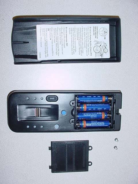
Click to zoom
Application Details
- Equipment Class
- DSC - Part 15 Security/Remote Control Transmitter
- Date of Grant
- Feb 28, 2007
- Application Purpose
- Original Equipment
- Date of Application
- Feb 28, 2007
- Equipment Note
- Remote Control Finger Print Transmitter
- Frequency Range
- 315.00000000 - 315.00000000
- Company
- Chamberlain Group LLC, The
- Country
- United States
Documents & Files
Document Text
Text extracted from the exhibit documents filed with the FCC. Open a document above to read the original.
Users Manual
Incorrect • Do not bend finger during the swipe as this will only scan the tip of your finger. • Swipe straight down, not at an angle. • Swipe flat, not tilted or rolled to one side. 1 Model 139.53555 Security✚ ® EntryEase NOTICE: To comply with FCC and or Industry Canada (IC) rules, adjustment or modifications of this receiver and/or transmitter are prohibited, except for changing the code setting or replacing the battery. THERE ARE NO OTHER USER SERVICEABLE PARTS. Tested to Comply with FCC Standards FOR HOME OR OFFICE USE. Operation is subject to the following two conditions: (1) this device may not cause harmful interference, and (2) this device must accept any interference received, including interference that may cause undesired operation. ® To prevent possible SERIOUS INJURY or DEATH from a moving gate or garage door: • Install Keyless Entry Control within sight of the garage door, out of reach of children at a minimum height of 5 feet (1.5 m), and away from all moving parts of door. • ALWAYS keep remote controls out of reach of children. NEVER permit children to operate, or play with remote control transmitters. • Activate gate or door ONLY when it can be seen clearly, is properly adjusted, and there are no obstructions to door travel. • ALWAYS keep gate or garage door in sight until completely closed. NEVER permit anyone to cross path of moving gate or door. WARNING CAUTION WARNING WARNING OVERVIEW For use with any 315 MHz SECURITY✚ ® garage door openers having a purple “learn” button. The EntryEase system uses biometric technology that enables an authorized user to gain access by scanning their fingerprint. The sensor strip on the unit makes a numeric template of the fingerprint that is unique only to that user. Resend Button:When pressed the traveling door will reverse. The fingerprint sensor is inactive for 15 seconds after valid swipe so reswiping will not reverse the door. Enroll Button:When pressed the Enroll LED will light up signaling that the device is in enroll mode. READY LED:Lit (green) when unit is ready to accept a fingerprint scan. PASS LED:Lit (green) when a scanned fingerprint matches a stored print. FAIL LED:Lit (red) when a scanned fingerprint does not match a stored print. RETRY LED:Lit (yellow) when another swipe is required. ENROLL LED:Lit (yellow) when the unit is in enroll mode. SEND LED:Lit (yellow) after a passed fingerprint scan and enables the Resend button for retransmission. NOTE:The term “enroll” refers to scanning the fingerprint so the device will recognize the user. The term “swipe” refers to the movement of the finger across the sensor strip. The term “LED” stands for Light Emitting Diode. INSTALLATION 1. Choose a convenient location for installation. Install out of the reach of children at a minimum height of 5 feet (1.5 m), away from all moving parts of door. For a one-piece door, choose the optional location shown in the illustration to avoid injury as the door swings up and out. 2. Remove the cover to access the top mounting hole by sliding past the “up stop” position. 3. Center the unit at eye level against the selected location. Mark the bottom edge at the center of the unit and remove from wall. Measure up 1-1/4" (3.2 cm) from this mark to locate the bottom mounting hole. Be sure that you have at least 11" (28 cm)above this mark to allow for the removal of cover. Drill a 1/8" (3.2 mm) pilot hole. Install bottom mounting screw, allowing 1/8" (3.2 mm) to protrude above surface. Position unit on screw head and adjust for snug fit. With cover off so top mounting hole is visible, mark the position of the hole. Remove unit and drill 1/8" (3.2 mm) pilot hole. Replace unit and complete installation of top screw, using care to avoid cracking plastic housing. Do not over tighten. To replace cover, insert into tracks and slide down. Door Jamb Edge (Optional) Keyless Entry Door Jamb Face (SECTIONAL DOOR ONLY) KEYLESS ENTRY MUST BE INSTALLED WITHIN SIGHT OF THE DOOR Exterior Front Wall 1-Piece or Sectional Door Typical Installation Send LED Pass LED Ready LED Enroll button Enroll LED Fail LED Retry LED Unit Cover Sensor Strip Resend button TIPS FOR SUCCESSFUL ENROLLMENT Correct 1. Make sure finger is free of grease or dirt. Place finger flat above the sensor strip with the top knuckle above the sensor. 2. Swipe finger straight down keeping firm contact with the sensor. The swipe should be a slow, constant speed. NOTE:Use the same finger for every swipe. UNIT MUST BE INSTALLED WITHIN SIGHT OF THE DOOR EntryEase 1-1/4" (3.2 cm) Back View 1. Slide cover past the normal “up stop” position. 2. Unscrew the two screws and remove the battery cover. 3. Replace the batteries. Screw the battery cover back on. 4. Slide entry cover back into place. To prevent possible SERIOUS INJURY or DEATH: • NEVER allow small children near batteries. • If battery is swallowed, immediately notify doctor. WARNING CAUTION WARNING WARNING THE BATTERY The batteries should produce power for at least one year. Replace when the Fail LED flashes during use. The unit requires 4 AAA batteries. Dispose of old batteries properly. FOR SERVICE DIAL OUR TOLL FREE NUMBER: 1-800-4-MY-HOME ® (1-800-469-4663) ENROLL FAIL RETRY SEND PASS READY ENROLL Screws Cover Battery Cover Replacement parts: Unit cover . . . . . . . . . . . . . . . . . . . . . . . . . . . . . . . . . . . . . . . .41A579 NOTE:The unit requires at least 3 good swipes to enroll a user. 1. Ensure that Enroll LED and Ready LED are lit and not flashing. 2. Swipe fingerprint down the sensor strip. The Pass LED will light briefly if a good swipe was achieved. If Retry LED lights followed by Ready LED, continue swiping until Pass LED is lit. 3. When enroll process is complete, the Enroll LED and Pass LED will flash. ENROLLING INITIAL USER ENROLL FAIL RETRY SEND PASS READY ENROLL TO ENROLL ADDITIONAL USERS The device can store up to four fingerprints at a time. 1. Turn unit on and wait for Ready LED to light. 2. Press and hold Enroll but…
Text truncated - open the document above for the full version.
Cover Letter(s)
845 Larch Ave. Elmhurst, IL 60126 Phone 630.993.6306 Fax 630.516.6863 Email: [email protected] February 15, 2007 Federal Communications Commission EQUIPMENT APPROVAL SERVICES PO Box 358315 Pittsburgh, PA 15251-5315 Re: FCC ID: HBW6421 Request for Confidentiality In accordance with 47 C.F.R. Section 0.459, we, The Chamberlain Group, Inc., hereby request confidentiality for the block diagram, schematic and product description presented for certification. In support of the Request for Confidentiality, the following is stated: Enclosed within this application is technical information which we deem to be trade secrets and proprietary. If made public, the information might be used to our disadvantage. To assist in assuring that we receive the full value of our product and protect its competitive posture, we respectfully request this grant of confidentiality. Sincerely, THE CHAMBERLAIN GROUP, INC. Barbara Kelkhoff Manager, Regulatory Affairs
Test Report
Engineering Test Report No. 37904-01 Measurement of RF Interference from a Model 1A6421 Fingerprint Scanner Transmitter For : Chamberlain Manufacturing 845 Larch Ave. Elmhurst, IL 60126 P.O. No. : 853334 Date Tested : January 26 through February 16, 2007 Test Personnel : Mark Longinotti, Daniel Crowder Specification : FCC "Code of Federal Regulations” Title 47 Part 15, Subpart C Industry Canada RSS-210 Industry Canada RSS-GEN Test Report By : Daniel Crowder Approved By : Raymond J. Klouda Registered Professional Engineer of Illinois - 44894 Elite Electronic Engineering Inc. 1516 Centre Circle Downers Grove, IL 60515 Tel : (630) 495-9770 Fax: (630) 495-9785 www.elitetest.com Engineering Test Report No. 37904-01 THIS REPORT SHALL NOT BE REPRODUCED, EXCEPT IN FULL, WITHOUT THE WRITTEN APPROVAL OF ELITE ELECTRONIC ENGINEERING INCORPORATED. Page 2 of 17 TABLE OF CONTENTS PARAGRAPH DESCRIPTION OF CONTENTS PAGE NO. 1 INTRODUCTION ............................................................................................................................................... 4 1.1 Scope of Tests .......................................................................................................................................... 4 1.2 Purpose .................................................................................................................................................... 4 1.3 Deviations, Additions and Exclusions....................................................................................................... 4 1.4 EMC Laboratory Identification .................................................................................................................. 4 1.5 Laboratory Conditions .............................................................................................................................. 4 2 APPLICABLE DOCUMENTS ............................................................................................................................ 4 3 TEST ITEM SETUP AND OPERATION............................................................................................................ 4 3.1 General Description .................................................................................................................................. 4 3.1.1 Power Input .......................................................................................................................................... 5 3.1.2 Peripheral Equipment........................................................................................................................... 5 3.1.3 Interconnect Cables ............................................................................................................................. 5 3.1.4 Grounding............................................................................................................................................. 5 3.2 Operational Mode ..................................................................................................................................... 5 3.3 Test Item Modifications............................................................................................................................. 5 4 TEST FACILITY AND TEST INSTRUMENTATION..........................................................................................5 4.1 Shielded Enclosure................................................................................................................................... 5 4.2 Test Instrumentation ................................................................................................................................. 5 4.3 Calibration Traceability ............................................................................................................................. 5 4.4 Measurement Uncertainty ........................................................................................................................ 6 5 TEST PROCEDURES ....................................................................................................................................... 6 5.1 Powerline Conducted Emissions .............................................................................................................. 6 5.1.1 Requirements ....................................................................................................................................... 6 5.2 Duty Cycle Factor Measurements ............................................................................................................ 6 5.2.1 Procedures ........................................................................................................................................... 6 5.2.2 Results.................................................................................................................................................. 6 5.3 Radiated Measurements .......................................................................................................................... 7 5.3.1 Requirements ....................................................................................................................................... 7 5.3.2 Procedures ........................................................................................................................................... 7 5.3.3 Results.................................................................................................................................................. 8 5.4 Occupied Bandwidth Measurements........................................................................................................ 8 5.4.1 Requirement ......................................................................................................................................... 8 5.4.2 Procedures ...................................................................................................................................…
Text truncated - open the document above for the full version.
Test Setup Photos
Engineering Test Report No. 37904-01 Page 11 of 17 Figure 2 Test Set-up for Radiated Emissions – Horizontal Polarity Test Set-up for Radiated Emissions – Vertical Polarity
Contact Information
Applicant
Thomas DeSilvia(Director Corporate Compliance)
Technical Contact
The Chamberlain Group, Inc.David R Bornemann
[email protected]630-516-6613
845 Larch Ave. · Elmhurst, Illinois · United States
Test Firm
Elite Electronic Engineering Inc.Kevin Halpin
Technical Specifications
| # | Rule Parts | Frequency Range | Power Output |
|---|---|---|---|
| 1 | 15.231 | 315 MHz - 315 MHz | - |
Other Applications from Chamberlain Group LLC, The

HBW73514
Jul 06, 2026iDock Link 2
Equipment Class
DSS - Part 15 Spread Spectrum TransmitterHBW-VKP2K
Jun 23, 2026SMART GARAGE VIDEO KEYPAD
Equipment Class
DTS - Digital Transmission System
HBWCHM1
Dec 03, 2025Wireless Chime
Equipment Class
DTS - Digital Transmission SystemHBWN519
Oct 10, 2024VEHICULAR GATE OPENER
Equipment Class
DSS - Part 15 Spread Spectrum TransmitterHBWN329
Sep 22, 2024Handheld Remote
Equipment Class
DSC - Part 15 Security/Remote Control Transmitter