HBW6597Part 15 Spread Spectrum Transmitter Transceiver
Chamberlain Group LLC, The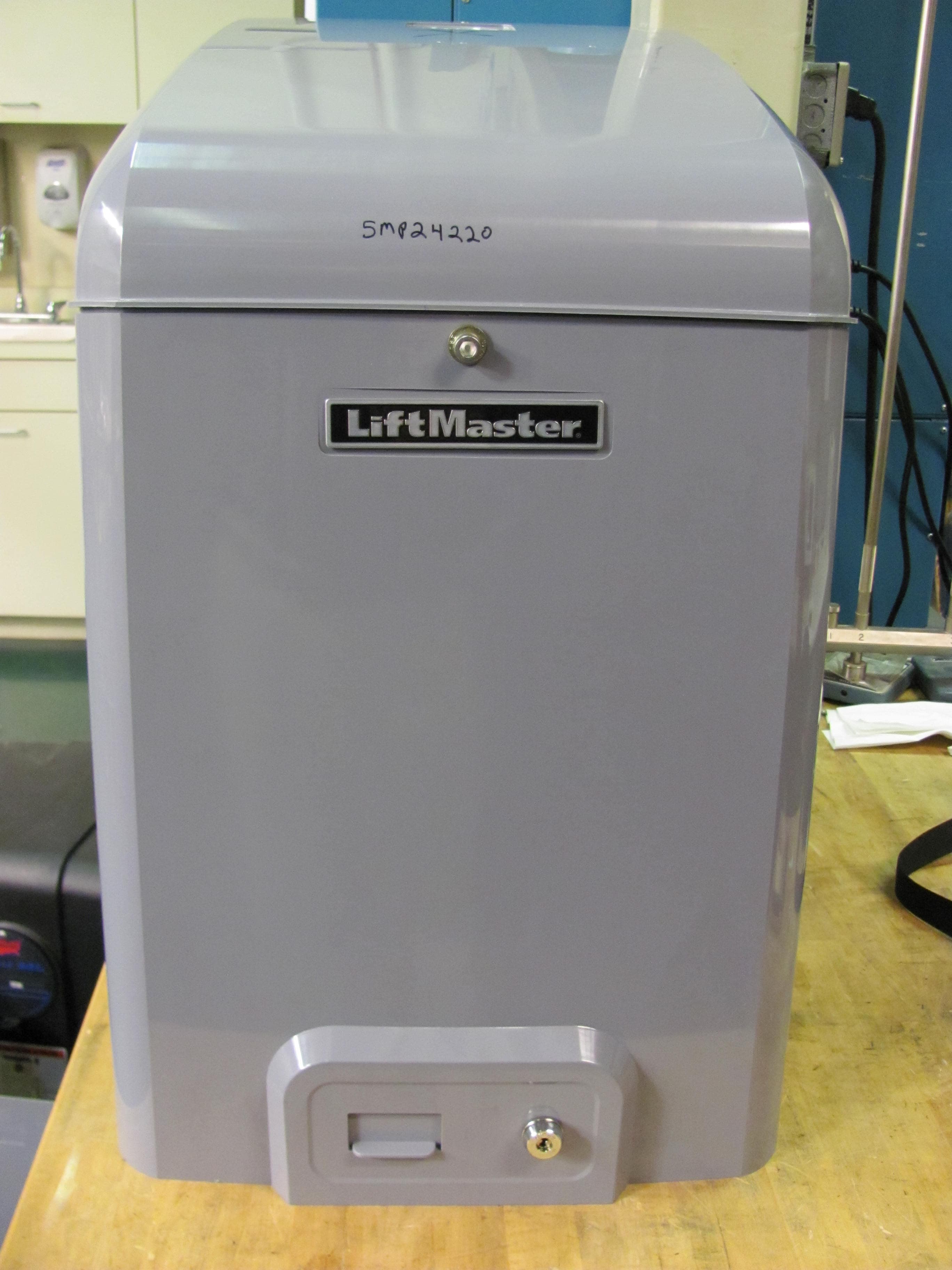
Click to zoom
Application Details
- Equipment Class
- DSS - Part 15 Spread Spectrum Transmitter
- Date of Grant
- May 25, 2011
- Application Purpose
- Original Equipment
- Date of Application
- May 25, 2011
- Equipment Note
- Part 15 Spread Spectrum Transmitter Transceiver
- Frequency Range
- 902.00000000 - 928.00000000
- Company
- Chamberlain Group LLC, The
- Country
- United States
Documents & Files
Document Text
Text extracted from the exhibit documents filed with the FCC. Open a document above to read the original.
Users Manual
CSW24V ™ & CSW24VH ™ VEHICULAR SWING GATE OPERATOR INSTALLATION MANUAL UL325 compliant UL991 compliant This model is for use on vehicular passage gates ONLY and not intended for use on pedestrian passage gates. This model is intended for use in Class I, II, III and IV vehicular swing gate applications. THIS PRODUCT IS TO BE INSTALLED AND SERVICED BY A TRAINED GATE SYSTEMS TECHNICIAN ONLY. Visit www.liftmaster.com to locate a professional installing dealer in your area. Your model may look different than the model illustrated in this manual. 1 When you see these Safety Symbols and Signal Words on the following pages, they will alert you to the possibility of serious injury or death if you do not comply with the warnings that accompany them. The hazard may come from something mechanical or from electric shock. Read the warnings carefully. When you see this Signal Word on the following pages, it will alert you to the possibility of damage to your gate and/or the gate operator if you do not comply with the cautionary statements that accompany it. Read them carefully. IMPORTANT NOTE • BEFORE attempting to install, operate or maintain the operator, you must read and fully understand this manual and follow all safety instructions. • DO NOT attempt repair or service of your gate operator unless you are an Authorized Service Technician. MECHANICAL ELECTRICAL SAFETY 1-7 Safety Symbol and Signal Word Review . . . . . . . . . . . . . . . . . . . . . . . . . . . . . . . 1 UL325 Model Classifications . . . . . . . . . . . . . . . . . . . . . . . . . . . . . . . . . . . . . . . . 2 Safety Installation Information . . . . . . . . . . . . . . . . . . . . . . . . . . . . . . . . . . . . . . 3 Gate Construction Information . . . . . . . . . . . . . . . . . . . . . . . . . . . . . . . . . . . . . . 4 Required Entrapment Protection Devices . . . . . . . . . . . . . . . . . . . . . . . . . . . . . . . 5 Important Safety Information . . . . . . . . . . . . . . . . . . . . . . . . . . . . . . . . . . . . .6-7 INTRODUCTION 8-9 Operator Specifications . . . . . . . . . . . . . . . . . . . . . . . . . . . . . . . . . . . . . . . . . . . 8 Carton Inventory & Operator Dimensions . . . . . . . . . . . . . . . . . . . . . . . . . . . . . . 8 Features . . . . . . . . . . . . . . . . . . . . . . . . . . . . . . . . . . . . . . . . . . . . . . . . . . . . . . 9 PREPARATION 10-11 Site Preparation . . . . . . . . . . . . . . . . . . . . . . . . . . . . . . . . . . . . . . . . . . . . .10-11 INSTALLATION 12-16 Standard Installation Only . . . . . . . . . . . . . . . . . . . . . . . . . . . . . . . . . . . . . .12-13 Compact Installation Only . . . . . . . . . . . . . . . . . . . . . . . . . . . . . . . . . . . . . .14-15 Installation Continued... . . . . . . . . . . . . . . . . . . . . . . . . . . . . . . . . . . . . . . . . . . 16 WIRING 17-21 Wire the Entrapment Protection Devices . . . . . . . . . . . . . . . . . . . . . . . . . . . . . . 17 Earth Ground Rod . . . . . . . . . . . . . . . . . . . . . . . . . . . . . . . . . . . . . . . . . . . . . . 17 Power Wiring . . . . . . . . . . . . . . . . . . . . . . . . . . . . . . . . . . . . . . . . . . . . . . . .18-19 Dual Gates Only . . . . . . . . . . . . . . . . . . . . . . . . . . . . . . . . . . . . . . . . . . . . .20-21 Connect Batteries . . . . . . . . . . . . . . . . . . . . . . . . . . . . . . . . . . . . . . . . . . . . . . . 21 ADJUSTMENT 22-23 Limit Setup . . . . . . . . . . . . . . . . . . . . . . . . . . . . . . . . . . . . . . . . . . . . . . . . . . . 22 Force Adjustment . . . . . . . . . . . . . . . . . . . . . . . . . . . . . . . . . . . . . . . . . . . . . . . 23 Obstruction Test . . . . . . . . . . . . . . . . . . . . . . . . . . . . . . . . . . . . . . . . . . . . . . . . 23 PROGRAMMING 24 Remote Controls . . . . . . . . . . . . . . . . . . . . . . . . . . . . . . . . . . . . . . . . . . . . . . . 24 Erase All Codes . . . . . . . . . . . . . . . . . . . . . . . . . . . . . . . . . . . . . . . . . . . . . . . . 24 OPERATION 25 Manual Disconnect . . . . . . . . . . . . . . . . . . . . . . . . . . . . . . . . . . . . . . . . . . . . . . 25 Reset Button . . . . . . . . . . . . . . . . . . . . . . . . . . . . . . . . . . . . . . . . . . . . . . . . . . 25 Remote Control . . . . . . . . . . . . . . . . . . . . . . . . . . . . . . . . . . . . . . . . . . . . . . . . 25 ADDITIONAL FEATURES 26-30 Control Board Overview . . . . . . . . . . . . . . . . . . . . . . . . . . . . . . . . . . . . . . . . . . 26 Accessory Features on Control Board . . . . . . . . . . . . . . . . . . . . . . . . . . . . . . . . 27 Expansion Board Overview . . . . . . . . . . . . . . . . . . . . . . . . . . . . . . . . . . . . . . . 28 Accessory Features on Expansion Board . . . . . . . . . . . . . . . . . . . . . . . . . . . . . . 29 Gate Operator Setup Examples . . . . . . . . . . . . . . . . . . . . . . . . . . . . . . . . . . . . 30 MAINTENANCE 31 Maintenance Chart . . . . . . . . . . . . . . . . . . . . . . . . . . . . . . . . . . . . . . . . . . . . . . 31 Batteries . . . . . . . . . . . . . . . . . . . . . . . . . . . . . . . . . . . . . . . . . . . . . . . . . . . . . 31 TROUBLESHOOTING 32-37 Control Board LEDs . . . . . . . . . . . . . . . . . . . . . . . . . . . . . . . . . . . . . . . . . . .32-33 Troubleshooting Chart . . . . . . . . . . . . . . . . . . . . . . . . . . . . . . . . . . . . . . . . .34-37 WIRING DIAGRAMS 38-39 Non Solar . . . . . . . . . . . . . . . . . . . . . . . . . . . . . . . . . . . . . . . . . . . . . . . . . . . . 38 Solar . . . . . . . . . . . . . . . . . . . . . . . . . . . . . . . . . . . . . . . . . . . . . . . . . . . . . . . . 39 ACCESSORIES 40 WARRANTY 41 TABLE OF CONTENTS SAFETY SYMBOL AND SIGNAL WORD REVIEW SAFETY 2 In order to complete a proper installation you must satisfy the entrapment protection chart shown. That means that the installation must have one primary means of entrapment protection and one independent secondary means of entrapment…
Text truncated - open the document above for the full version.
Users Manual
9 FEATURES INTRODUCTION FEATURES OPERATOR FEATURES CONTROL BOARD FEATURES EXPANSION BOARD FEATURES • Advanced "Centerpiece" Control Board • EMI AC Power Surge Protection and Filter Board - Main AC voltage input selection: 120 Vac (factory setting) or 240 Vac (field change) • DC motor • AC powered with integrated battery backup • 24 Vdc accessory power • Programmable with up to 50 remote controls, compatible with: Security MAX codes at either 310, 315, or 390 MHz • Manual - Secure power failure selection • SAMS compatible • Slow-start and slow-stop gate motion • Reset Button • Audible Alarm • Internal Heater option (factory installed or field installed) 120 Vac powered ONLY • Non-Scissor Action swing arm with easy arm disconnect • Integrated internal antenna with external antenna option • Electronic Limit adjustment and control • Adjustable reversal force • Adjustable Timer-to-Close (TTC) • Maximum Run Timer • Bipart Delay switch (dual gate applications) • Feedback and Diagnostic LEDs • Integrated Radio Receiver, Single Button Control (SBC) and 3-Button Station control, three radio frequencies supporting Security MAX • COMMANDS: - OPEN, CLOSE, or STOP: accessory connection and on-board button - Single Button Close (SBC): accessory connection - FIRE DEPARTMENT OPEN: accessory connection - INTEGRATED RADIO RECEIVER: • LOOPS: - EXIT, SHADOW, or INTERRUPT LOOP: plug-in loop detector (Model SPI) and accessory connection • Plug-in Loop Detector Connectors (Model LOOPDETLM Loop Detector) - SHADOW - INTERRUPT - EXIT, with Fail Safe/Fail Secure selection • Quick-Close ON/OFF selection switch • AC Fail Open/Battery selection switch • Low Battery Open/Close selection switch • Anti-Tail ON/OFF selection switch • Single Button Control (SBC) accessory connection • 3-Button station accessory connection • AUX Relays (2) each independently selectable operation: - OPEN LIMIT: ON at open limit switch - CLOSE LIMIT: ON at close limit switch - GATE MOVING: ON with gate moving - PRE-ALERT DELAY: ON 3 seconds before gate motion - TAMPER: ON when gate manually pulled from close limit - POWER: ON with AC or Solar power available - CYCLE QUANTITY: LEDs blink operational cycle count 10 PREPARATION Conduit must be UL approved for low and high voltage. Consider the operator placement BEFORE installing the pad or post. Gate must be constructed and installed according to ASTM F2200 standards (refer to page 4). Gate must fit specifications of operator (refer to specifications). Concrete Pads GATE CONDUIT & CONCRETE PAD SITE PREPARATION Check the national and local building codes BEFORE installation. 11 SITE PREPARATION VEHICLE LOOPS The vehicle loops allow the gate to stay open when vehicles are obstructing the gate path. Suggested for vehicles 14 feet (4.27 m) or longer. Vehicle loops are not required but are recommended. ! ! Entrapment protection devices are required to protect against any entrapment or safety conditions encountered in your gate application (refer to page 5 for more details). Install warning signs on both sides of the gate. Proper grounding gives an electrical charge, such as from an electrical static discharge or a near lightning strike, a path from which to dissipate its energy safely into the earth. Without this path, the intense energy generated by lightning could be directed towards the gate operator. Although nothing can absorb the tremendous power of a direct lightning strike, proper grounding can protect the gate operator in most cases. (Inside Property) Entrapment Danger Warning Signs Check national and local codes for proper depth SAFETY EARTH GROUND ROD TYPES OF INSTALLATIONS STANDARD INSTALLATION COMPACT INSTALLATION UPHILL DRIVEWAY INSTALLATION The illustration is an example of a standard installation. The illustration is an example of a compact installation. If the operator arm will hit an obstruction when the gate is in the open position follow the directions for Compact Installation. The illustration is an example of an uphill driveway installation. If installing the operator on a hill, a special swivel arm and hinges are required (not provided). (Inside Property) (Inside Property) (Outside Property) (Side View) 12 MOUNTING FOOTPRINT 13.6" 11" 14" .63" CONDUIT LOCATION 12.2" 6.1" 2.49" 14.6" 17" 12" Output Shaft STANDARD INSTALLATION ONLY INSTALLATION STANDARD INSTALLATION ONLY For compact installation start on page 14. DETERMINE LOCATION FOR CONCRETE PAD AND OPERATOR DO NOT run the operator until instructed. Below is a recommended guide for positioning the concrete pad: Measure 1/4 the length of the gate from the gate hinge center. This is A. Subtract 12-16 inches from A to get B, the distance from the center of the output shaft to the center of the gate hinge. Open the gate 90°. The distance from the gate to the center of the output shaft must be a minimum of 9 inches. 1/4 1/4 1/4 A B minimum of 9" Output Shaft 1 2 3 28" 24" 90° Gate Hinge TOP VIEW OF OPERATOR AND GATE CONCRETE PAD AND OPERATOR ATTACHMENT Check the national and local building codes before installation. NOTE: When lifting the operator use the handle to avoid damaging the operator. Install the electrical conduit. Pour a concrete pad (reinforced concrete is recommended). The concrete pad should be 6 inches above the ground and deeper than the frost line. Ensure the pad is tall enough to avoid possible flooding. Secure the operator to the concrete pad with appropriate fasteners. NOTE: An alternative to a concrete pad is to post mount the operator (refer to accessories). 4 Concrete Anchors 1/2" x 3 1/2" Below the frost line. Check all national and local codes. 6" Above Ground 28" 24" 1 3 2 1 2 3 1 2 3 13 STANDARD INSTALLATION ONLY INSTALLATION STANDARD INSTALLATION ONLY POSITION THE GATE BRACKET NOTE: It may be necessary to attach horizontal reinforcement to the gate before attaching the gate bracket. Position the operator arm onto the output shaft so that the pin slides into the slot. Measure 1/4 the length of the gate f…
Text truncated - open the document above for the full version.
Users Manual
18 POWER WIRING WIRING POWER WIRING This operator can be wired for either 120 Vac or 240 Vac or a solar panel (not provided). Follow the directions according to your application. For dual gate applications, power will have to be connected to each operator. Main power supply and control wiring MUST be run in separate conduits. 240 VAC ONLY If using the 240 Vac option a heater cannot be used. The accessory outlet is disabled and cannot be used with the 240 Vac option. Remove the outlet housing from the chassis by removing the screws (3). Pull the outlet housing out and locate the power wiring connector on the EMI board. Unplug the power wiring connector from the 120 Vac socket (factory default location) and plug it into the 240 Vac socket. Replace the outlet housing by securing with the screws. The operator is now set for 240 Vac operation. 2 3 1 4 Outlet Housing Power Wiring Connector (120 Vac Socket, factory default) 240 Vac Socket AMERICAN WIRE GAUGE (AWG) MAXIMUM WIRE LENGTH (120 VAC) MAXIMUM WIRE LENGTH (240 VAC) 14 130 feet260 feet 12205 feet410 feet 10325 feet650 feet 8520 feet1040 feet 6825 feet1650 feet 41312 feet2624 feet NUMBER OF CYCLES PER DAY Swing Gate Installation (12 ft. 800 lb. gate) AccessoriesSingle Gate Solenoid Lock50 mA100 mA300 mA 7AH Batteries (standard) 33AH Batteries (optional) TRANSFORMER POWERED ContinuosContinuos ✔ ContinuosContinuos ✔ ContinuosContinuos ✔ ContinuosContinuos ✔ ContinuosContinuos BATTERY POWERED 100275 ✔ 35230 ✔ 45270 ✔ 45270 ✔ 40260 AC POWER SWITCH The AC Power switch on the operator will turn the incoming 120/240 Vac power ON or OFF. The operator's AC Power switch ONLY turns off AC power to the control board and DOES NOT turn off battery power. AC Power Switch EMI Board 19 120 VAC AND 240 VAC POWER WIRING CONTINUED... POWER WIRING WIRING NOT PROVIDED. SEE ACCESSORIES. The solar panel(s) must be located in an open area clear of obstructions and shading for the entire day. The gate operator is not supported in northern climates where temperatures reach below -4 ̊F. This is due to cold weather and a reduced number of hours of sunlight during the winter months. Cycle rate may vary from solar chart for areas that reach below 32 ̊F. Solar panels should be cleaned on a regular basis for best performance to ensure proper operation. For solar applications, a minimum of two 10W solar panels in series and two 7AH batteries are recommended. For Zone 3 cold weather sites, two 33AH batteries are recommended. We recommend LiftMaster low power draw accessories to minimize power draw, refer to accessory page. SOLAR PANEL(S) NOT AVAILABLE NOT AVAILABLE 1 1 1 2 3 3 2 Locate the red and black wires connected to the J5 plug labeled DC POWER on the control board. Unplug the wires from the bridge rectifier. Connect the red (+) wire from the J5 plug to the red wire from the solar panel. Connect the black (-) wire from the J5 plug to the black wire from the solar panel. 1 2 3 Junction Box Cover Heater (if applicable) 120 Vac ONLY Red Wire Black Wire Bridge Rectifier J5 Plug Turn off the AC power from the main power source circuit breaker. Run the AC power wires to the operator. Remove the junction box cover. Connect the green wire to the earth ground rod wire using a wire nut. Connect the white wire to NEUTRAL using a wire nut. Connect the black wire to HOT using a wire nut. HEATER WIRING: NOTE: If your operator comes with a heater it will have to be wired. The heater may be wired to the internal receptacle or a separate junction box. If wiring the heater to the internal receptacle, thread the heater wires through the same knockout as the power wires. Connect the heater wires to the power wires with wire nuts (green to green, black to black, and white to white). Replace the junction box cover. Ensure the wires are not pinched. 1 2 3 4 5 6 7 NUMBER OF CYCLES PER DAY (SOLAR) Swing Gate Installation (12 ft. 800 lb. gate) CONFIGURATIONZONE 1 (6 Hrs sunlight/day) ZONE 2 (4 Hrs Sunlight/day) ZONE 3 (2 Hrs Sunlight/day) TransmittersWireless Dual GateExpansion Board connected1 Loop7AH Batteries (standard)33AH Batteries (optional)7AH Batteries (standard)33AH Batteries (optional)7AH Batteries (standard)33AH Batteries (optional) 20W SOLAR PANEL 516631391113 ✔ 496430381012 ✔✔ 4459253357 ✔✔ 4660263478 ✔✔✔✔ 4054202812 40W SOLAR PANEL 9014470923139 ✔ 8814269903038 ✔✔ 8313764852533 ✔✔ 8513966872634 ✔✔✔✔ 7913259802028 60W SOLAR PANEL 90222901445166 ✔ 88220881424964 ✔✔ 83215831374459 ✔✔ 85217851394660 ✔✔✔✔ 79210791324054 20 DUAL GATES ONLY TO ACTIVATE THE WIRELESS FEATURE: Press and release the LEARN button on the first operator. The green XMITTER LED will light. Press and release the LEARN button again on the same operator. The yellow NETWORK LED will light. Press and release the LEARN button on the second operator. The green XMITTER LED will light. Press and release the LEARN button again on the second operator. The yellow NETWORK LED blink (operator will beep) then turn off indicating successful activation. 1 2 3 4 TO DEACTIVATE THE WIRELESS FEATURE: Press and release the LEARN button on either operator. The green XMITTER LED will light. Press and release the LEARN button again on the same operator. The yellow NETWORK LED will light. Press and hold the LEARN button for 5 seconds. The yellow NETWORK LED will blink (operator will beep) then turn off indicating successful deactivation. 1 2 3 DUAL GATES ONLY WIRING WIRELESS DUAL GATES Turn on power to the operator. Outside Property Inside Property ! ! COMMLINK B A OM N.C. COMMLINK B A OM N.C. 1 2 3 4 2 1 3 4 Before digging, contact local underground utility locating companies. Use PVC conduit to prevent damage to cables. Trench across driveway to bury the extension cable. Connect the wires from the extension cable to the Comm Link terminals on the primary gate operator control board. Route the extension cable to the secondary gate operator's control board. Connect the wires from the extension cable to the Comm Link terminals on the sec…
Text truncated - open the document above for the full version.
Users Manual
This model is for use on vehicular passage gates ONLY and not intended for use on pedestrian passage gates. This model is intended for use in Class I, II, III and IV vehicular slide gate applications. UL325 compliant UL991 compliant CSL24V ™ & CSL24VH ™ VEHICULAR SLIDE GATE OPERATOR INSTALLATION MANUAL THIS PRODUCT IS TO BE INSTALLED AND SERVICED BY A TRAINED GATE SYSTEMS TECHNICIAN ONLY. Visit www.liftmaster.com to locate a professional installing dealer in your area. Your model may look different than the model illustrated in this manual. 1 SAFETY 1-7 Safety Symbol and Signal Word Review . . . . . . . . . . . . . . . . . . . . . . . . . . . . . . . 1 UL325 Model Classifications . . . . . . . . . . . . . . . . . . . . . . . . . . . . . . . . . . . . . . . . 2 Safety Installation Information . . . . . . . . . . . . . . . . . . . . . . . . . . . . . . . . . . . . . . 3 Gate Construction Information . . . . . . . . . . . . . . . . . . . . . . . . . . . . . . . . . . . . . . 4 Required Entrapment Protection Devices . . . . . . . . . . . . . . . . . . . . . . . . . . . . . . . 5 Important Safety Information . . . . . . . . . . . . . . . . . . . . . . . . . . . . . . . . . . . . .6-7 INTRODUCTION 8-9 Operator Specifications . . . . . . . . . . . . . . . . . . . . . . . . . . . . . . . . . . . . . . . . . . . 8 Carton Inventory & Operator Dimensions . . . . . . . . . . . . . . . . . . . . . . . . . . . . . . 8 Features . . . . . . . . . . . . . . . . . . . . . . . . . . . . . . . . . . . . . . . . . . . . . . . . . . . . . . 9 PREPARATION 10-11 Site Preparation . . . . . . . . . . . . . . . . . . . . . . . . . . . . . . . . . . . . . . . . . . . . .10-11 INSTALLATION 12-13 Determine Location for Concrete Pad and Operator . . . . . . . . . . . . . . . . . . . . . 12 Concrete Pad and Operator Attachment . . . . . . . . . . . . . . . . . . . . . . . . . . . . . . 12 Standard Installation Only . . . . . . . . . . . . . . . . . . . . . . . . . . . . . . . . . . . . . . . . 13 Rear Installation Only . . . . . . . . . . . . . . . . . . . . . . . . . . . . . . . . . . . . . . . . . . . 13 WIRING 14-18 Wire the Entrapment Protection Devices . . . . . . . . . . . . . . . . . . . . . . . . . . . . . . 14 Earth Ground Rod . . . . . . . . . . . . . . . . . . . . . . . . . . . . . . . . . . . . . . . . . . . . . . 14 Power Wiring . . . . . . . . . . . . . . . . . . . . . . . . . . . . . . . . . . . . . . . . . . . . . . . .15-16 Dual Gates Only . . . . . . . . . . . . . . . . . . . . . . . . . . . . . . . . . . . . . . . . . . . . .17-18 Connect Batteries . . . . . . . . . . . . . . . . . . . . . . . . . . . . . . . . . . . . . . . . . . . . . . . 18 ADJUSTMENT 19-20 Limit Setup . . . . . . . . . . . . . . . . . . . . . . . . . . . . . . . . . . . . . . . . . . . . . . . . . . . 19 Force Adjustment . . . . . . . . . . . . . . . . . . . . . . . . . . . . . . . . . . . . . . . . . . . . . . . 20 Obstruction Test . . . . . . . . . . . . . . . . . . . . . . . . . . . . . . . . . . . . . . . . . . . . . . . . 20 PROGRAMMING 21 Remote Controls . . . . . . . . . . . . . . . . . . . . . . . . . . . . . . . . . . . . . . . . . . . . . . . 21 Erase All Codes . . . . . . . . . . . . . . . . . . . . . . . . . . . . . . . . . . . . . . . . . . . . . . . . 21 Green Xmitter and Yellow Network LED . . . . . . . . . . . . . . . . . . . . . . . . . . . . . . 21 OPERATION 22 Reset Switch . . . . . . . . . . . . . . . . . . . . . . . . . . . . . . . . . . . . . . . . . . . . . . . . . . 22 Remote Control . . . . . . . . . . . . . . . . . . . . . . . . . . . . . . . . . . . . . . . . . . . . . . . . 22 ADDITIONAL FEATURES 23-27 Gate Operator Setup Examples . . . . . . . . . . . . . . . . . . . . . . . . . . . . . . . . . . . . 23 Control Board Overview . . . . . . . . . . . . . . . . . . . . . . . . . . . . . . . . . . . . . . . . . . 24 Accessory Features on Control Board . . . . . . . . . . . . . . . . . . . . . . . . . . . . . . . . 25 Expansion Board Overview . . . . . . . . . . . . . . . . . . . . . . . . . . . . . . . . . . . . . . . 26 Accessory Features on Expansion Board . . . . . . . . . . . . . . . . . . . . . . . . . . . . . . 27 ACCESSORIES 28 MAINTENANCE 29 Maintenance Chart . . . . . . . . . . . . . . . . . . . . . . . . . . . . . . . . . . . . . . . . . . . . . . 29 Batteries . . . . . . . . . . . . . . . . . . . . . . . . . . . . . . . . . . . . . . . . . . . . . . . . . . . . . 29 Drive Chain . . . . . . . . . . . . . . . . . . . . . . . . . . . . . . . . . . . . . . . . . . . . . . . . . . . 29 TROUBLESHOOTING 30-35 Control Board LEDs . . . . . . . . . . . . . . . . . . . . . . . . . . . . . . . . . . . . . . . . . . .30-31 Troubleshooting Chart . . . . . . . . . . . . . . . . . . . . . . . . . . . . . . . . . . . . . . . . .32-35 WIRING DIAGRAM 36-37 Non Solar . . . . . . . . . . . . . . . . . . . . . . . . . . . . . . . . . . . . . . . . . . . . . . . . . . . . 36 Solar . . . . . . . . . . . . . . . . . . . . . . . . . . . . . . . . . . . . . . . . . . . . . . . . . . . . . . . . 37 WARRANTY BACK COVER When you see these Safety Symbols and Signal Words on the following pages, they will alert you to the possibility of serious injury or death if you do not comply with the warnings that accompany them. The hazard may come from something mechanical or from electric shock. Read the warnings carefully. When you see this Signal Word on the following pages, it will alert you to the possibility of damage to your gate and/or the gate operator if you do not comply with the cautionary statements that accompany it. Read them carefully. IMPORTANT NOTE • BEFORE attempting to install, operate or maintain the operator, you must read and fully understand this manual and follow all safety instructions. • DO NOT attempt repair or service of your gate operator unless you are an Authorized Service Technician. MECHANICAL ELECTRICAL SAFETY SYMBOL AND SIGNAL WORD REVIEW SAFETY TABLE OF CONTENTS 2 CLASS I – RESIDENTIAL VEHICULAR GAT…
Text truncated - open the document above for the full version.
Users Manual
13 REAR INSTALLATION ONLY 3 2 3 1 2 STANDARD INSTALLATION ONLY 1 2 Open the gate and line up the front bracket so the chain will be level with the idler pulley and parallel to the ground. Weld the front bracket in this position. Close the gate and line up the rear bracket so the chain will be level with the idler pulley and parallel to the ground. Weld the rear bracket in this position. Route the chain through the operator. Connect the chain to the brackets using the eye bolt hardware. Chain should not be too tight or have excessive slack. DO NOT run the operator until instructed. 3 NOTE: The chain should have no more than 1 inch of sag for every 10 feet of chain length. DO NOT run the operator until instructed. The chain should have no more than 1 inch of sag for every 10 feet of chain length. 1 NOTE: This installation will require two extra idler pulleys. Make sure all exposed pinch points are guarded. Refer to Gate Construction Information on page 4. Move the back pulley to the bottom hole in the operator. Close the gate and align the bottom bracket so the chain will be level with the bottom idler pulley and parallel to the ground. Weld the bottom bracket in this position Align the top bracket so the chain will be level with the top idler pulley and parallel to the ground. Weld the upper bracket in this position. Route the chain through the operator. Connect the chain to the brackets using the eye bolt hardware. Chain should not be too tight or have excessive slack. 1 2 3 4 4 4 4 5 5 STANDARD INSTALLATION ONLY + REAR INSTALLATION ONLY INSTALLATION Idler Pulley MUST have safety cover. 14 EARTH GROUND ROD Use the proper earth ground rod for your local area. The ground wire must be a single, whole piece of wire. Never splice two wires for the ground wire. If you should cut the ground wire too short, break it, or destroy its integrity, replace it with a single wire length. Install the earth ground rod within 3 feet of the operator. Run wire from the earth ground rod to the operator. NOTE: If the operator is not grounded properly the range of the remote controls will be reduced. 1 2 WIRE THE ENTRAPMENT PROTECTION DEVICES + EARTH GROUND ROD WIRING To prevent SERIOUS INJURY or DEATH from a moving gate: • Entrapment protection devices MUST be installed to protect anyone who may come near a moving gate. • Locate entrapment protection devices to protect in BOTH the open and close gate cycles. • Locate entrapment protection devices to protect between moving gate and RIGID objects, such as posts or walls. Connect the entrapment protection device to the EYES EDGE terminal on the control board: • Open Entrapment Protection: Connect wires from the entrapment protection device to the Open Inputs on the EYES EDGE terminal. • Close Entrapment Protection: Connect wires from the entrapment protection device to the Close Inputs on the EYES EDGE terminal. 1 WIRE THE ENTRAPMENT PROTECTION DEVICES Entrapment protection devices are required. Refer to page 5 for more information regarding application. TO ERASE LEARNED MONITORED PHOTOELECTRIC SENSORS Remove the photoelectric sensor wires from the terminal block. Press both Set Limit Buttons simultaneously until the SET LEDs turn on. Press both Set Limit Buttons again to turn off the SET LEDs. 1 2 3 SET OPEN SET CLOSE MOVE GATE OFF 5 10 60 180 MIN MAX (SECONDS) OFF ON OPEN CLOSE STOP INPUT POWER BATT CHARGING TIMER GATE MOVING BATT LOW ACC PWR OVLD DIAGNOSTIC CODES BIPART DELAY LEARN TEST BUTTONS TIMER TO CLOSE REVERSAL FORCE STATUS: OPEN CLOSE STOP COMMON “FIRE DEPT.” OPEN EXIT SHADOW INTERRUPT COMMLINK B A - + - + EYES EDGE LOCK N.O. COM N.C. + - + - ACCESSORY POWER ON SW. EXP. BOARD RESETENCODER ID IN ALARM SECURE / MANUAL + - MOTOR + - DC POWER + - BATT BATT FUSE 30A 32V 1 6 3 4 XMITTER NETWORK PRESS & RELEASE TO BEGIN SETUP LIMIT CLOSE OPEN DC POWER FUSE 30A 32V CLASS 2 SUPPLY 24 VOLTS INTERRUPT - + - + EYES EDGE CLOSE OPEN Open Direction (+) 1 Open Direction (-) Close Direction (+) Close Direction (-) Check national and local codes for proper depth To Operator 15 POWER WIRING WIRING POWER WIRING This operator can be wired for either 120 Vac or 240 Vac or a solar panel (not provided). Follow the directions according to your application. For dual gate applications, power will have to be connected to each operator. Main power supply and control wiring MUST be run in separate conduits. 240 VAC ONLY Remove the outlet housing from the chassis by removing the screws (3). Pull the outlet housing out and locate the power wiring connector on the EMI board. Unplug the power wiring connector from the 120 Vac socket (factory default location) and plug it into the 240 Vac socket. Replace the outlet housing by securing with the screws. The operator is now set for 240 Vac operation. 2 3 1 4 If using the 240 Vac option a heater cannot be used. The accessory outlet is disabled and cannot be used with the 240 Vac option. Outlet Housing Power Wiring Connector (120 Vac Socket, factory default) 240 Vac Socket NUMBER OF CYCLES PER DAY Slide Gate Installation (16 ft. 1000 lb. gate) AccessoriesSingle Gate Solenoid Lock50 mA100 mA300 mA 7AH Batteries (standard) 33AH Batteries (optional) TRANSFORMER POWERED ContinuosContinuos ✔ ContinuosContinuos ✔ ContinuosContinuos ✔ ContinuosContinuos ✔ ContinuosContinuos BATTERY POWERED 100275 ✔ 35230 ✔ 45270 ✔ 45270 ✔ 40260 AMERICAN WIRE GAUGE (AWG) MAXIMUM WIRE LENGTH (120 VAC) MAXIMUM WIRE LENGTH (240 VAC) 14 130 feet260 feet 12205 feet410 feet 10325 feet650 feet 8520 feet1040 feet 6825 feet1650 feet 41312 feet2624 feet AC POWER SWITCH The AC Power switch on the operator will turn the incoming 120/240 Vac power ON or OFF. The operator's AC Power switch ONLY turns off AC power to the control board and DOES NOT turn off battery power. AC Power Switch EMI Board 16 POWER WIRING CONTINUED... POWER WIRING WIRING NOT PROVIDED. SEE ACCESSORIES. The solar panel(s) must be located in an open area clear of obstructions and shading for the entire day. Th…
Text truncated - open the document above for the full version.
Contact Information
Applicant
Thomas DeSilvia(Director Corporate Compliance)
Technical Contact
Underwriters Laboratories Inc.Michael Ferrer
[email protected]847-664-1312
333 Pfingsten Rd. · Northbrook · United States
Non-Technical Contact
Underwriters Laboratories Inc.Michael Ferrer
[email protected]847-664-1312
Test Firm
UL LLCRick Titus
Technical Specifications
| # | Rule Parts | Frequency Range | Power Output |
|---|---|---|---|
| 1 | 15C | 902 MHz - 928 MHz | 20.60 mW |
Other Applications from Chamberlain Group LLC, The

HBW73514
Jul 06, 2026iDock Link 2
Equipment Class
DSS - Part 15 Spread Spectrum TransmitterHBW-VKP2K
Jun 23, 2026SMART GARAGE VIDEO KEYPAD
Equipment Class
DTS - Digital Transmission System
HBWCHM1
Dec 03, 2025Wireless Chime
Equipment Class
DTS - Digital Transmission SystemHBWN519
Oct 10, 2024VEHICULAR GATE OPENER
Equipment Class
DSS - Part 15 Spread Spectrum TransmitterHBWN329
Sep 22, 2024Handheld Remote
Equipment Class
DSC - Part 15 Security/Remote Control Transmitter