HBW6761Gate Operator Ebox Assembly
Chamberlain Group LLC, The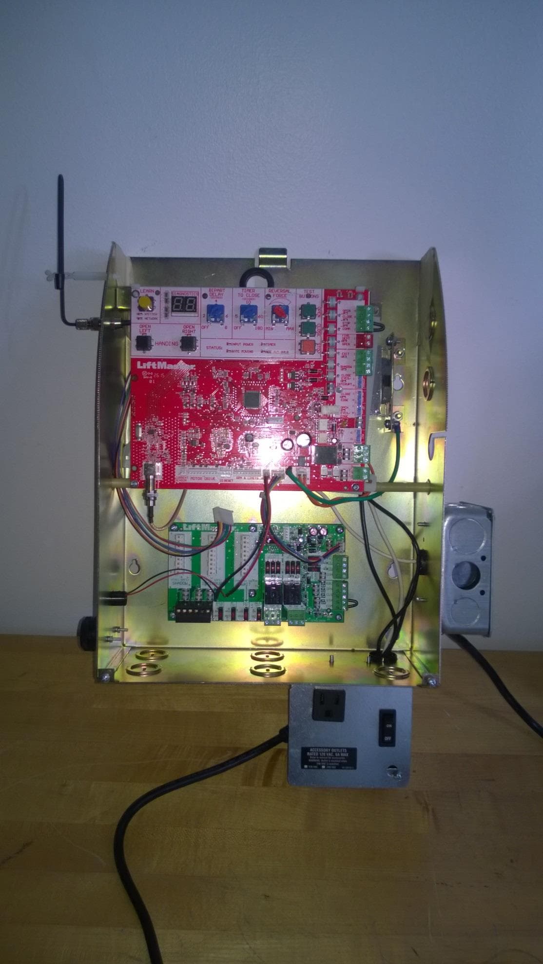
Click to zoom
Application Details
- Equipment Class
- DSS - Part 15 Spread Spectrum Transmitter
- Date of Grant
- Sep 13, 2015
- Application Purpose
- Original Equipment
- Date of Application
- Sep 13, 2015
- Equipment Note
- Gate Operator Ebox Assembly
- Frequency Range
- 902.25000000 - 926.75000000
- Company
- Chamberlain Group LLC, The
- Country
- United States
Documents & Files
Document Text
Text extracted from the exhibit documents filed with the FCC. Open a document above to read the original.
Users Manual
• THIS PRODUCT IS TO BE INSTALLED AND SERVICED BY A TRAINED GATE SYSTEMS TECHNICIAN ONLY. • This model is for use on vehicular passage gates ONLY and not intended for use on pedestrian passage gates. • This model is intended for use in Class I, II, III and IV vehicular slide gate applications. • Visit LiftMaster.com to locate a professional installing dealer in your area. • This gate operator is compatible with MyQ ® and Security+ 2.0™ accessories. ELITE SERIES COMMERCIAL HIGH-TRAFFIC AC SLIDE GATE OPERATOR INSTALLATION MANUAL LiftMaster 845 Larch Avenue Elmhurst, IL 60126-1196 SL3000101U 1 HP Single Phase SL3000501U 1/2 HP Single Phase Model SL3000U OPERATOR REQUIRES EXTERNAL MONITORED ENTRAPMENT PROTECTION DEVICE TABLE OF CONTENTS SAFETY 1 SAFETY SYMBOL AND SIGNAL WORD REVIEW .................................. 1 USAGE CLASS ....................................................................................... 2 UL325 ENTRAPMENT PROTECTION REQUIREMENTS .......................... 2 SAFETY INSTALLATION INFORMATION ................................................ 3 GATE CONSTRUCTION INFORMATION .................................................. 4 INTRODUCTION 5 CARTON INVENTORY ............................................................................ 5 TOOLS NEEDED ..................................................................................... 5 OPERATOR SPECIFICATIONS ................................................................ 6 SITE PREPARATION .............................................................................. 7 OVERVIEW OF TYPICAL INSTALLATION ............................................... 8 INSTALLATION 9 TYPES OF INSTALLATIONS ................................................................... 9 INSTALLATION 10 DETERMINE LOCATION FOR CONCRETE PAD AND OPERATOR ......... 10 INSTALL THE OPERATOR .................................................................... 11 ATTACH THE CHAIN ............................................................................ 12 INSTALL ENTRAPMENT PROTECTION ................................................ 13 EARTH GROUND ROD ......................................................................... 15 POWER WIRING .................................................................................. 15 DUAL GATES ONLY ............................................................................. 17 INSTALL THE COVER ........................................................................... 18 ADJUST THE HANDING AND LIMITS .................................................. 19 OBSTRUCTION TEST ........................................................................... 20 OPERATOR OVERVIEW 21 CONTROL BOARD OVERVIEW 22 CONTROL BOARD REFERENCE ........................................................... 22 LEARN BUTTON ................................................................................... 23 DIAGNOSTIC DISPLAY ........................................................................ 23 HANDING BUTTONS ............................................................................ 23 BIPART DELAY .................................................................................... 23 TIMER-TO-CLOSE (TTC) ..................................................................... 23 FORCE DIAL ......................................................................................... 24 TEST BUTTONS ................................................................................... 24 STATUS LEDS ...................................................................................... 24 WIRE ACCESSORIES TO CONTROL BOARD 25 THREE BUTTON CONTROL STATION .................................................. 25 FIRE DEPARTMENT ............................................................................. 25 LOOPS ................................................................................................. 25 PHOTOELECTRIC SENSORS AND EDGE SENSORS ............................. 26 LOCKS ................................................................................................. 26 EXPANSION BOARD OVERVIEW 27 EXIT FAIL SWITCH ............................................................................... 27 AC FAIL SWITCH ................................................................................. 27 ANTI TAIL SWITCH .............................................................................. 27 QUICK CLOSE SWITCH ........................................................................ 27 AUXILIARY RELAY 1 AND 2 ................................................................ 28 WIRE ACCESSORIES TO EXPANSION BOARD 29 PHOTOELECTRIC SENSORS AND EDGE SENSORS ............................. 29 CONTROL STATION ............................................................................. 29 LOOPS ................................................................................................. 30 ADDITIONAL WIRING 30 SAMS WIRING WITH RELAYS NOT ENERGIZED ................................. 30 FIELD WIRING ..................................................................................... 31 PROGRAMMING 32 REMOTE CONTROLS (NOT PROVIDED) .............................................. 32 LIFTMASTER INTERNET GATEWAY (NOT PROVIDED) ....................... 33 ERASE ALL CODES .............................................................................. 33 TO REMOVE AND ERASE ALL MONITORED ENTRAPMENT PROTECTION DEVICES .............................................................................................. 33 SETTINGS 34 GATE OPERATOR SETUP EXAMPLES ................................................. 34 DUAL GATE SETTINGS ........................................................................ 35 MAINTENANCE 36 IMPORTANT SAFETY INFORMATION .................................................. 36 MAINTENANCE .................................................................................... 36 TROUBLESHOOTING 37 DIAGNOSTIC CODES ......................…
Text truncated - open the document above for the full version.
Users Manual
11 STEP 2 INSTALL THE OPERATOR Attach the operator to the concrete pad with appropriate fasteners. The gate operator should be installed near the front roller of the gate or near the back of the gate (in the OPEN position). The space between the gate and the output sprocket must be a minimum of 4 inches. 4 Concrete Anchors 1/2" x 3 1/2" Below the frost line. Check all national and local codes. 6" Above Ground 24" (61 cm) 24" (61 cm) INSTALLATION MOUNTING FOOTPRINT 10.4" (26.4 cm) 10.3" (26.2 cm) POST MOUNT An alternative to a concrete pad is to post mount the operator. 4" (10 cm) (chain location) (operator) 12 STEP 3 ATTACH THE CHAIN DO NOT run the operator until instructed. 1. Manually open the gate and line up the front bracket so the chain will be level with the idler pulley and parallel to the ground. Weld the front bracket in this position. 2. Manually close the gate and line up the rear bracket so the chain will be level with the idler pulley and parallel to the ground. Weld the rear bracket in this position. 3. Route the chain through the operator. 4. Connect the chain to the brackets using the eye bolt hardware. Chain should not be too tight or have excessive slack. 5. Remove the pin from the vent plug on the gear box. The chain should have no more than 1 inch of sag for every 10 feet of chain length. INSTALLATION 2 3 1 4 5 REAR INSTALLATION DO NOT run the operator until instructed. NOTE: This installation will require two extra idler pulleys. Make sure all exposed pinch points are guarded. Refer to Gate Construction Information on page 4. 1. Move the back pulley to the bottom hole in the operator. 2. Manually close the gate and align the bottom bracket so the chain will be level with the bottom idler pulley and parallel to the ground. Weld the bottom bracket in this position. 3. Align the top bracket so the chain will be level with the top idler pulley and parallel to the ground. Weld the upper bracket in this position. 4. Route the chain through the operator. 5. Connect the chain to the brackets using the eye bolt hardware. Chain should not be too tight or have excessive slack. 6. Remove the pin from the vent plug on the gear box (see above). The chain should have no more than 1 inch of sag for every 10 feet of chain length. Pin Vent Plug Idler Pulley MUST have safety cover. 13 To prevent SERIOUS INJURY or DEATH from a moving gate: • ALL gate operator systems REQUIRE two independent entrapment protection systems for each entrapment zone. • Entrapment protection devices MUST be installed to protect anyone who may come near a moving gate. • Locate entrapment protection devices to protect in BOTH the open and close gate cycles. • Locate entrapment protection devices to protect between moving gate and RIGID objects, such as posts, walls, pillars, or columns. NON-CONTACT SENSORS If the photoelectric sensor beam gets blocked while the gate is moving, the gate will stop and reverse. The gate will not be able to travel in that direction until the obstruction is cleared. Monitored photoelectric sensors MUST be used. If a monitored photoelectric sensor is not working or loses power or the beam is blocked, then ALL gate operation in that direction will stop. This operator contains an inherent (internal) entrapment protection system and REQUIRES the addition of an external monitored entrapment protection system (non-contact photoelectric sensor or contact edge sensor) for EACH entrapment zone prior to gate movement. A monitored device sends a pulsed signal to the operator so the operator is aware of the device. If the operator does not receive the signal from the device it will not run. An entrapment zone is every location or point of contact where a person can become entrapped between a moving gate and a stationary object. Your application may contain one or many entrapment zones. Property owners are obligated to test entrapment protection devices monthly. Use only LiftMaster approved entrapment protection devices (refer to the accessory page). CONTACT SENSORS (EDGE SENSORS) If the electrically activated edge sensor comes in contact with an obstruction while the gate is moving, the gate will stop and reverse. The gate will not be able to travel in that direction until the obstruction is cleared. INSTALLATION STEP 4 INSTALL ENTRAPMENT PROTECTION Outside Property Inside Property Inside Property Outside Property Monitored Photoelectric Sensors Sensors for Open Cycle Sensors for Close Cycle Inside Property Inside Property Edge Sensor for Open Cycle Edge Sensor for Open Cycle Edge Sensor for Close Cycle 14 INSTALLATION STEP 4 continued... INSTALL ENTRAPMENT PROTECTION There are three options for wiring the entrapment protection devices depending on the specific device and how the device will function. Refer to the specific entrapment protection device manual for more information. These entrapment protection device inputs are for monitored devices, which include pulsed photoelectric sensors, resistive edge sensors, and pulsed edge sensors. Only one monitored entrapment protection device may be wired to each input. Additional entrapment protection devices may be wired to the expansion board. CONTROL BOARD CLOSE EYES/INTERRUPT (2 Terminals) The CLOSE EYES/INTERRUPT input is for photoelectric sensor entrapment protection for the close direction. When an obstruction is sensed during gate closing the gate will open to the full open position and resets the Timer-to-Close. This input will be disregarded during gate opening. CLOSE EDGE (2 Terminals) The CLOSE EDGE input is for edge sensor entrapment protection for the close direction. When an obstruction is sensed during gate closing the gate will reverse to the full open position, disengaging the Timer-to-Close. This input will be disregarded during gate opening. OPEN EYES/EDGE (2 Terminals) The OPEN EYES/EDGE input is for photoelectric sensor or edge sensor entrapment protection for the open direction. When an obstruction is sensed during gate openin…
Text truncated - open the document above for the full version.
Users Manual
23 BIPART DELAY TIMER-TO-CLOSE (TTC) LEARN BUTTON DIAGNOSTIC DISPLAY CONTROL BOARD OVERVIEW The diagnostic display will show the operator type, firmware version, and codes. The operator type will display as “SL” followed by a “30” which indicates the operator type as SL3000U. The firmware version will show after the operator type, example “1.2”. For more information about the codes refer to the Troubleshooting section. HANDING BUTTONS The TTC is factory set to OFF (0). Rotate the TIMER-TO-CLOSE dial to the desired setting (0 to 180 seconds). Any radio command, single button control, or CLOSE command on the control board prior to the TTC expiring will close the gate. The TTC is reset by any signals from the open controls, loops, close edges, and close photoelectric sensors. 0 seconds (OFF) The gate will remain open until the operator receives another command from a control. 1-180 seconds (ON) The gate will automatically close after the specified time period. Used in dual gate applications where a maglock, solenoid lock, or decorative overlay would require one gate to close before the other. The BIPART DELAY is also used in applications where one gate travels a longer distance than the other. ON The operator with the BIPART DELAY dial ON will delay from the close limit when opening and be the first to close from the open limit. OFF No affect. BIPART DELAY 2 4 6 8 The handing buttons are used to determine which direction the gate will open and they are also used to set the limits (refer to the Adjustment section). OPEN RIGHT If the operator is installed on the right side of the drive when looking out of the property, a swing gate will swing to the right (turn counter clockwise) when opening and a slide gate will slide to the right when opening. OPEN LEFT If the operator is mounted on the left side of the drive when looking out of the property, a swing gate will swing to the left (turn clockwise) when opening and a slide gate will slide to the left when opening. NOTE: For gates installed on the outside of the property, the setting will be opposite. Determine the direction by looking towards the property from the outside. HANDING OPEN LEFT OPEN RIGHT The LEARN button is used for programming (refer to Programming). 24 LEDSTATEDEFINITION INPUT POWER OFFOFF state ONAC power available TIMER OFFThe timer is disabled ONThe timer is enabled 1 blink/secondThe timer is running 2 blinks/secondThe timer is paused 8 blinks/secondThe timer is cancelled GATE MOVING OFFThe gate is stopped ONThe gate is opening or closing 1 blink/secondE1 (single entrapment) 8 blinks/secondE2 (double entrapment) ACC PWR OVLD OFFOFF state ONAccessory overload protector opened STATUS LEDS TEST BUTTONS CONTROL BOARD OVERVIEW FORCE DIAL 1 2 3 4 5 6 7 8 9 10 The force setting should be high enough that the gate will not reverse by itself nor cause nuisance interruptions, but low enough to prevent serious injury to a person. The force setting is the same for both the open and close gate directions. Settings 1-3: Fixed force settings (the force will not adjust due to gate wear or temperature changes) Settings 4-10: Automatically increase the force due to gate wear or temperature changes ADJUST THE FORCE 1. Open and close the gate with the TEST BUTTONS, ensuring that the gate is stopping at the proper open and close limit positions. If the gate is not stopping at the proper limits, adjust the force dial accordingly. 2. Place a solid object between the open gate and a rigid structure. Ensure that the gate, the solid object, and the rigid structure can withstand the forces generated during this obstruction test. 3. Run the gate in the close direction. The gate should stop and reverse upon contact with the solid object. If the gate does not reverse off the solid object, reduce the force setting by turning the force control slightly counter-clockwise. The gate should have enough force to reach both the open and close limits, but MUST reverse after contact with a solid object. 4. Repeat the test for the open direction. Used to operate the gate (OPEN, STOP and CLOSE). Also used to view the code history (refer to the Troubleshooting section). 25 TERMINALSFUNCTIONWIRING EXAMPLE OPEN and COMM Opens a closed gate. Hard open (maintained switch overrides external safeties and resets alarm condition). If maintained, pauses Timer-to-Close at OPEN limit. Opens a closing gate and holds open an open gate (within line-of-sight). CLOSE and COMM Closes an open gate. Hard close (maintained switch overrides external safeties and resets alarm condition within line-of-sight) STOP and COMM Stops a moving gate. Hard stop (maintained switch overrides Open and Close commands and resets alarm condition). If maintained, cancels Timer-to-Close at OPEN limit. Overrides Open and Close commands (within line-of-sight). + + + N.C. – TERMINALSFUNCTIONWIRING EXAMPLE FIRE DEPT (-) and OPEN (+) FIRE DEPT and OPEN terminals act as a hard open. Maintained input overrides (ignores) external safeties (photoelectric sensor and edge), pauses Timer-to-Close momentary input logic as single button control and safeties remain active, re-enables Timer-to-Close. + – The Loop terminals are used for connecting loops and various control devices such as telephone entry keypads, vehicle probes, etc. Connect the accessory to the terminals based on how the accessory should function. TERMINALSFUNCTIONWIRING EXAMPLE EXIT and COM This input is a soft open command (maintained switch does not override external safeties and does not reset alarm condition). Used for exit probe, telephone entry, external exit loop detector, or any device that would command the gate to open. • Opens a closing gate and holds open an open gate, if maintained, pauses Timer-to-Close at OPEN limit. + + + – – – SHADOW and COM This input is used for external shadow loop detector when loop is positioned under the swing of the gate. • Holds open gate at open limit • Only active when the gate is at the OPEN limit, disregarded…
Text truncated - open the document above for the full version.
Cover Letter(s)
845 Larch Ave. Elmhurst, IL 60126 Phone 630.993.6306 Fax 630.516.6863 Email: [email protected] August 20, 2015 Federal Communication Commission Equipment Authorization Division Application Processing Branch 7435 Oakland Mills Road Columbia, Maryland 21046 c.c. UL LLC. 333 Pfingsten Road Northbrook, IL 60062 To whom it may concern: I, the undersigned, hereby authorize Bart Mucha, of UL LLC, to act on our behalf in all manners relating to application for equipment authorization, including signing of all documents relating to these matters. Any and all acts carried out by Bart Mucha of UL on our behalf, shall have the same effect as acts of our own. I, the undersigned, hereby certify that we are not subject to a denial of federal benefits, that includes FCC benefits, pursuant to Section 5301 of the Anti-Drug Abuse Act of 1988, 21 U.S.C. 853(a). In authorizing UL as our agent, we still recognize that we are responsible to: a) Comply with the relevant provisions of the certification program; b) Make all necessary arrangements for the conduct of the evaluation, including provision for Examining documentation and access to all areas, records (including internal audit reports) And personnel for the purposes of evaluation (e.g. testing, inspection, assessment, surveillance, reassessment) and resolution of complaints; c) Make claims regarding certification only in respect of the scope for which certification has been granted; d) Do not use our product certification in such a manner as to bring the Certification Division Into disrepute and not make any statement regarding our product certification which the Certification Division may consider misleading or unauthorized; e) Upon suspension or cancellation of certification, discontinue use of all advertising matter That contains any reference thereto and returns any certification documents as required by the Certification Division; f) Use certification only to indicate the products are certified as being in conformity with Specified standards; g) Endeavor to ensure that no certificate or report nor any part thereof is used in a misleading manner; h) Ensure that any reference to our product certification in communication media such as documents, brochures or advertising, complies with the requirements of the Certification Division; i) Keep a record of all complaints made known to the us relating to the product’s compliance with requirements of the relevant standard and to make these records available to the Certification Division when requested; j) Take appropriate action with respect to such complaints and any deficiencies found in products or services that affect compliance with the requirements for certification; k) Document the actions taken. This authorization is valid until further written notice from the applicant. Yours sincerely, Barbara Kelkhoff Regulatory Project Manager II Chamberlain Group, Inc. 845 Larch Ave. Elmhurst, IL. 60126
Cover Letter(s)
845 Larch Ave. Elmhurst, IL 60126 Phone 630.993.6306 Fax 630.516.6863 Email: [email protected] August 20, 2015 Federal Communication Commission Equipment Authorization Division Application Processing Branch 7435 Oakland Mills Road Columbia, Maryland 21046 FCC ID: HBW1D6761 for circuit assembly 1D6761-1 Request for Confidentiality In accordance with 47 C.F.R. Section 0.457 and 0.459, we, Chamberlain Group, Inc., hereby request confidentiality for the block diagram, schematic and product description presented for certification. In support of the Request for Confidentiality, the following is stated: Enclosed within this application is technical information which we deem to be trade secrets and proprietary. If made public, the information might be used to our disadvantage. To assist in assuring that we receive the full value of our product and protect its competitive posture, we respectfully request this grant of confidentiality. I would appreciate your prompt attention to the submittal. If there are any questions, please call me at 630-993-6306 or send a fax to 630-516- 6863. Sincerely, Barbara Kelkhoff Regulatory Project Manager II Chamberlain Group, Inc. 845 Larch Ave. Elmhurst, IL. 60126
Cover Letter(s)
845 Larch Avenue September 9, 2015 Elmhurst, IL 60126 Subject: Chamberlain/Liftmaster Professional Installation Requirement To Whom It May Concern, I have provided below the justification for considering the AC Nitrous Gate series of Residential and Commercial Gate Operators as requiring professional installation, and therefore the use of standard antenna connector is acceptable under FCC regulations. Background Our Residential and Commercial Gate Operator line is available with the standard external antenna connector, where the installer fits the supplied antenna, provided in our hardware bag, approved by the FCC for use with these products. The external antenna, through this standard connector, provides us with the greatest range and performance. Justification Our Residential and Commercial Gate Operator line is sold exclusively through our controlled dealer network distribution channel. Chamberlain and LiftMaster (tradename) do not sell these products through any retail chain to the general public, nor does it offer the product for sale by mail order. Requiring Professional Installation Chamberlain/LiftMaster states on the cover page of our Installation Manuals that only installation and service is to be done by trained professional installers/technicians. As stated above, the product is available only through our dealer distribution channels. The installation is essential to be completed by a trained professional to ensure the system will operate with the performance that is required. Application The Nitrous AC gate operator line of products are intended for residential/commercial/industrial use only, a typical example would installation for a gated community or at a warehouse to allow for delivery vehicles. They are only intended for trained professional installations and adjustments. Thank you for your attention, End and Regards, Barbara Kelkhoff Regulatory Project Manager II Chamberlain Group, Inc. 845 Larch Ave. Elmhurst, IL. 60126
External Photos
FCC ID: HBW6761 IC ID: 2666A-6761 FCC ID: HBW6761 IC ID: 2666A-6761 FCC ID: HBW6761 IC ID: 2666A-6761 FCC ID: HBW6761 IC ID: 2666A-6761
ID Label/Location Info
FCC ID: HBW6761 IC ID: 2666A-6761 Label Location
Internal Photos
FCC ID: HBW6761 IC ID: 2666A-6761 Top Side Back Side FCC ID: HBW6761 IC ID: 2666A-6761 Radio Part
Parts List/Tune Up Info
[Type text] 845 Larch Ave., Elmhurst, IL. 60126 Phone: (630) 516‐6711 Fax: (630) 516‐6871 Web: http://www.chamberlaingroup.com Email: [email protected] Antenna Antenna Tx High Band Rx Low & High Band Antenna System: One single Antenna is used for Transmit and Receive. It is a monopole Antenna, professionally installed. Calculated Gain of 0.5dB. Antenna wire is phosphor bronze, spring temper coated With black insulation enamel. Connector is F type straight plug, nickel plated. RF Transceiver
RF Exposure Info
NVLAP Lab code: 100414-0 FCC Part 1 Subpart I FCC Part 2 Subpart J INDUSTRY CANADA RSS 102 ISSUE 5 RF EXPOSURE REPORT FOR Gate Opeatro Controller with 900MHz FHSS Trasceiver MODEL NUMBER: 001D6761 FCC ID: HBW6761 IC ID: 2666A-6761 REPORT NUMBER: 10693059A ISSUE DATE: August 31, 2015 Prepared for Chamberlain Group Inc. 845 N. Larch Ave Elmhurst, IL 60126 USA Prepared by UL LLC 333 Pfingsten Rd. Northbrook, IL 60062 TEL: (847) 272-8800 REPORT NO: 10693059C DATE: Augutst 31, 2015 FCC ID: HBW6761 IC: 2666A-6761 Page 2 of 10 UL LLC FORM NO: CCSUP4701I 333 Pfingsten Rd., Northbrook, IL 60062, USA TEL: (847) 272-8800 This report shall not be reproduced except in full, without the written approval of UL LLC Revision History Rev. Issue Date Revisions Revised By -- 8-31- 2015 Initial Issue BM REPORT NO: 10693059C DATE: Augutst 31, 2015 FCC ID: HBW6761 IC: 2666A-6761 Page 3 of 10 UL LLC FORM NO: CCSUP4701I 333 Pfingsten Rd., Northbrook, IL 60062, USA TEL: (847) 272-8800 This report shall not be reproduced except in full, without the written approval of UL LLC TABLE OF CONTENTS 1. ATTESTATION OF TEST RESULTS .................................................................................... 4 2. TEST METHODOLOGY ........................................................................................................ 5 3. REFERENCES ...................................................................................................................... 5 4. FACILITIES AND ACCREDITATION .................................................................................... 5 5. MAXIMUM PERMISSIBLE RF EXPOSURE ......................................................................... 6 5.1. FCC RULES ................................................................................................................... 6 5.2. IC RULES ....................................................................................................................... 7 5.3. EQUATIONS .................................................................................................................. 8 5.4. LIMITS AND IC EXEMPTION ......................................................................................... 9 6. RF EXPOSURE RESULTS ................................................................................................. 10 REPORT NO: 10693059C DATE: Augutst 31, 2015 FCC ID: HBW6761 IC: 2666A-6761 Page 4 of 10 UL LLC FORM NO: CCSUP4701I 333 Pfingsten Rd., Northbrook, IL 60062, USA TEL: (847) 272-8800 This report shall not be reproduced except in full, without the written approval of UL LLC 1. ATTESTATION OF TEST RESULTS COMPANY NAME: Chamberlain Group Inc. 845 N. Larch Ave Elmhurst, IL 60126 EUT DESCRIPTION: Gate Operator Controller with 900MHz FHSS Trasceiver MODEL: 001D6761 SERIAL NUMBER: Prototype DATE TESTED: April 20, 2015 – August 25, 2015 APPLICABLE STANDARDS STANDARD TEST RESULTS FCC PART 1 SUBPART I & PART 2 SUBPART J Pass INDUSTRY CANADA RSS 102 ISSUE 5 Pass UL LLC calculated the RF Exposure of the above equipment in accordance with the requirements set forth in the above standards, using test results reported in the test report documents referenced below and/or documentation furnished by the applicant. All indications of Pass/Fail in this report are opinions expressed by UL LLC based on interpretations of these calculations. The results show that the equipment is capable of demonstrating compliance with the requirements as documented in this report. Note: The results documented in this report apply only to the tested sample, under the conditions and modes of operation as described herein. This document may not be altered or revised in any way unless done so by UL LLC and all revisions are duly noted in the revisions section. Any alteration of this document not carried out by UL LLC will constitute fraud and shall nullify the document. This report must not be used by the client to claim product certification, approval, or endorsement by NVLAP, NIST, any agency of the Federal Government, or any agency of any government. Approved & Released For Tested By: UL LLC By: Michael Ferrer Bart Mucha UL LLC UL LLC REPORT NO: 10693059C DATE: Augutst 31, 2015 FCC ID: HBW6761 IC: 2666A-6761 Page 5 of 10 UL LLC FORM NO: CCSUP4701I 333 Pfingsten Rd., Northbrook, IL 60062, USA TEL: (847) 272-8800 This report shall not be reproduced except in full, without the written approval of UL LLC 2. TEST METHODOLOGY All calculations were made in accordance with FCC OET Bulletin 65 Edition 97-01 and IC Safety Code 6. 3. REFERENCES All measurements were made as documented in test report UL LLC Document 10693059A & B. for operation in the 900 MHz band. Output power, and Antenna gain data is excerpted from product documentation provided by the applicant and applicable test report. Duty cycle is assumed 100% as worst case. 4. FACILITIES AND ACCREDITATION The test sites and measurement facilities used to collect data are located at 333 Pfingsten Road, Northbrook, IL 60062 USA. UL NBK is accredited by NVLAP, Laboratory Code 100414…
Text truncated - open the document above for the full version.
Contact Information
Applicant
Thomas DeSilvia(Director Corporate Compliance)
Technical Contact
UL LLCBart Mucha
[email protected]847-664-1216
333 Pfingsten Rd · Northbrook, Illinois · United States
Non-Technical Contact
UL LLCBart Mucha
[email protected]847-664-1216
Test Firm
UL LLCRick Titus
Technical Specifications
| # | Rule Parts | Frequency Range | Power Output |
|---|---|---|---|
| 1 | 15C | 902.25 MHz - 926.75 MHz | 10.23 mW |
Other Applications from Chamberlain Group LLC, The

HBW73514
Jul 06, 2026iDock Link 2
Equipment Class
DSS - Part 15 Spread Spectrum TransmitterHBW-VKP2K
Jun 23, 2026SMART GARAGE VIDEO KEYPAD
Equipment Class
DTS - Digital Transmission System
HBWCHM1
Dec 03, 2025Wireless Chime
Equipment Class
DTS - Digital Transmission SystemHBWN519
Oct 10, 2024VEHICULAR GATE OPENER
Equipment Class
DSS - Part 15 Spread Spectrum TransmitterHBWN329
Sep 22, 2024Handheld Remote
Equipment Class
DSC - Part 15 Security/Remote Control Transmitter