HBW7545Linear gate operator w/ 900MHz FHSS transceiver
Chamberlain Group LLC, The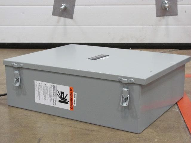
Click to zoom
Application Details
- Equipment Class
- DSS - Part 15 Spread Spectrum Transmitter
- Date of Grant
- Jan 26, 2012
- Application Purpose
- Original Equipment
- Date of Application
- Jan 26, 2012
- Equipment Note
- Linear gate operator w/ 900MHz FHSS transceiver
- Frequency Range
- 902.25000000 - 926.75000000
- Company
- Chamberlain Group LLC, The
- Country
- United States
Documents & Files
Document Text
Text extracted from the exhibit documents filed with the FCC. Open a document above to read the original.
Users Manual
LA500 & LA500-S VEHICULAR SWING GATE OPERATOR INSTALLATION MANUAL UL325 compliant UL991 compliant This model is for use on vehicular passage gates ONLY and not intended for use on pedestrian passage gates. This model is intended for use in Class I, II, III and IV vehicular swing gate applications. THIS PRODUCT IS TO BE INSTALLED AND SERVICED BY A TRAINED GATE SYSTEMS TECHNICIAN ONLY. Visit www.liftmaster.com to locate a professional installing dealer in your area. Your model may look different than the model illustrated in this manual. 1 When you see these Safety Symbols and Signal Words on the following pages, they will alert you to the possibility of serious injury or death if you do not comply with the warnings that accompany them. The hazard may come from something mechanical or from electric shock. Read the warnings carefully. When you see this Signal Word on the following pages, it will alert you to the possibility of damage to your gate and/or the gate operator if you do not comply with the cautionary statements that accompany it. Read them carefully. IMPORTANT NOTE • BEFORE attempting to install, operate or maintain the operator, you must read and fully understand this manual and follow all safety instructions. • DO NOT attempt repair or service of your gate operator unless you are an Authorized Service Technician. MECHANICAL ELECTRICAL SAFETY 1-7 Safety Symbol and Signal Word Review . . . . . . . . . . . . . . . . . . . . . . . . . . . . . . . 1 UL325 Model Classifications . . . . . . . . . . . . . . . . . . . . . . . . . . . . . . . . . . . . . . . . 2 Safety Installation Information . . . . . . . . . . . . . . . . . . . . . . . . . . . . . . . . . . . . . . 3 Gate Construction Information . . . . . . . . . . . . . . . . . . . . . . . . . . . . . . . . . . . . . . 4 Required Entrapment Protection Devices . . . . . . . . . . . . . . . . . . . . . . . . . . . . . . . 5 Important Safety Information . . . . . . . . . . . . . . . . . . . . . . . . . . . . . . . . . . . . .6-7 INTRODUCTION 8-9 Operator Specifications . . . . . . . . . . . . . . . . . . . . . . . . . . . . . . . . . . . . . . . . . . . 8 Carton Inventory & Operator Dimensions . . . . . . . . . . . . . . . . . . . . . . . . . . . . . . 8 Features . . . . . . . . . . . . . . . . . . . . . . . . . . . . . . . . . . . . . . . . . . . . . . . . . . . . . . 9 PREPARATION 10-12 Site Preparation . . . . . . . . . . . . . . . . . . . . . . . . . . . . . . . . . . . . . . . . . . . . .10-11 Mounting Options . . . . . . . . . . . . . . . . . . . . . . . . . . . . . . . . . . . . . . . . . . . . . . 12 INSTALLATION 13-17 Manual Release . . . . . . . . . . . . . . . . . . . . . . . . . . . . . . . . . . . . . . . . . . . . . . . . 13 Determine the Position of the Post Bracket . . . . . . . . . . . . . . . . . . . . . . . . . . . . 13 Determine the Position of the Gate Bracket . . . . . . . . . . . . . . . . . . . . . . . . . . . 14 Weld the Brackets . . . . . . . . . . . . . . . . . . . . . . . . . . . . . . . . . . . . . . . . . . . . . . 14 Attach the Operator to the Brackets . . . . . . . . . . . . . . . . . . . . . . . . . . . . . . . . . 15 Standard Control Box. . . . . . . . . . . . . . . . . . . . . . . . . . . . . . . . . . . . . . . . . . . . 16 Large Metal Control Box (XLM) . . . . . . . . . . . . . . . . . . . . . . . . . . . . . . . . . . . . 17 WIRING 18-24 Wire the Entrapment Protection Devices . . . . . . . . . . . . . . . . . . . . . . . . . . . . . . 18 Earth Ground Rod . . . . . . . . . . . . . . . . . . . . . . . . . . . . . . . . . . . . . . . . . . . . . . 18 Wire the Operator Arm to the Control Board . . . . . . . . . . . . . . . . . . . . . . . . . . . 19 Dual Gates Only . . . . . . . . . . . . . . . . . . . . . . . . . . . . . . . . . . . . . . . . . . . . .20-21 Power Wiring . . . . . . . . . . . . . . . . . . . . . . . . . . . . . . . . . . . . . . . . . . . . . . . .22-23 Connect Batteries . . . . . . . . . . . . . . . . . . . . . . . . . . . . . . . . . . . . . . . . . . . . .23-24 Engage the Operator . . . . . . . . . . . . . . . . . . . . . . . . . . . . . . . . . . . . . . . . . . . . 24 ADJUSTMENT 25-26 Limit and Force Adjustment . . . . . . . . . . . . . . . . . . . . . . . . . . . . . . . . . . . . .25-26 Obstruction Test . . . . . . . . . . . . . . . . . . . . . . . . . . . . . . . . . . . . . . . . . . . . . . . . 26 PROGRAMMING 27 Remote Controls . . . . . . . . . . . . . . . . . . . . . . . . . . . . . . . . . . . . . . . . . . . . . . . 27 Erase All Codes . . . . . . . . . . . . . . . . . . . . . . . . . . . . . . . . . . . . . . . . . . . . . . . . 27 OPERATION 28 Manual Release . . . . . . . . . . . . . . . . . . . . . . . . . . . . . . . . . . . . . . . . . . . . . . . . 28 Reset Button . . . . . . . . . . . . . . . . . . . . . . . . . . . . . . . . . . . . . . . . . . . . . . . . . . 28 Remote Control . . . . . . . . . . . . . . . . . . . . . . . . . . . . . . . . . . . . . . . . . . . . . . . . 28 Party Mode . . . . . . . . . . . . . . . . . . . . . . . . . . . . . . . . . . . . . . . . . . . . . . . . . . . 28 MAINTENANCE 29 Maintenance Chart . . . . . . . . . . . . . . . . . . . . . . . . . . . . . . . . . . . . . . . . . . . . . . 29 Batteries . . . . . . . . . . . . . . . . . . . . . . . . . . . . . . . . . . . . . . . . . . . . . . . . . . . . . 29 ADDITIONAL FEATURES 30-35 Control Board Overview . . . . . . . . . . . . . . . . . . . . . . . . . . . . . . . . . . . . . . . . . . 30 Accessory Features on Control Board . . . . . . . . . . . . . . . . . . . . . . . . . . . . . . . . 31 Expansion Board Overview . . . . . . . . . . . . . . . . . . . . . . . . . . . . . . . . . . . . . . . 32 Accessory Features on Expansion Board . . . . . . . . . . . . . . . . . . . . . . . . . . . . . . 33 Gate Operator Setup Examples . . . . . . . . . . . . . . . . . . . . . . . . . . . . . . . . . . . . 34 Limit Setup with a Remote Control . . . . . . . . . . . . . . . . . . . . . . . . . . . . . . . …
Text truncated - open the document above for the full version.
Users Manual
19 Insert the operator cable through the watertight connector mounted in the bottom of the control box. Extend the operator cable and wires to the Gate 1 connector and connect as shown. Tighten watertight connector nut. WIRE THE OPERATOR ARM TO THE CONTROL BOARD 1 2 3 If installing one operator, proceed to page 22. If installing two operators, continue to the next page. WIRE THE OPERATOR TO THE CONTROL BOARD WIRING ! GATE 1 BR GRN WHT YEL BLU RE GATE 2 BR RN WHT YEL BLU RE + - S LAR / HARGER 20 DUAL GATES ONLY DUAL GATES ONLY WIRING Before digging, contact local underground utility locating companies. The following items are required to complete the junction box installation: • 4 x 4 Junction Box with 3/4" NPT threaded port holes • Screws • PVC Conduit Trench across driveway to bury the extension cable. Use PVC conduit to prevent damage to cables. Open the junction box by removing screws (4) and set aside. Mount the junction box within 3 feet (0.9 m) of second operator. Route operator cable and extension cable through watertight connector nut and watertight connector. Insert cables and watertight connectors into the holes in the bottom of the junction box (not provided). Feed extension cable through PVC conduit and secure with nut. INSTALL THE EXTENSION CABLE AND JUNCTION BOX 1 2 4 5 6 3 ! ! PVC Conduit Junction Box Extension Cable Operator Cable Within 3 feet Insert wires from extension cable and operator cable into the terminal block connector as shown (like-colored wires must face each other). Put wires inside of junction box. Secure operator and extension cables with watertight connector nut. Reinstall cover. 1 2 3 4 WIRE THE EXTENSION CABLE TO THE SECONDARY OPERATOR Terminal Block Connector Extension CableOperator Cable 21 DUAL GATES ONLY WIRING DUAL GATES ONLY SET OPEN SET C OSE MO E G TE F 5 10 0 80 ( E ON S) O F ON O SE STOP NP T POWER B TT C ARG NG MER ATE M V NG B TT L W ACC WR VL I GNOS I CO ES STATUS EX T S AD W C OSE E NTE RUP LOCK N O M N C + + AC ESS RY OWER ON SW XP B ARD M T ER RS & L A E T BG N MIT 2 + + J5 + OL R / HAR ER 15 + A T + DC POW R ID R SET AL RM BR GRN WT E B U ED BR GRN WT E LU R D LOSE OFF ON BIPART DELAY L TIMER SET THE BIPART DELAY Occasionally in dual gate installations, one gate will need to open first and close second. This would happen if there was an ornamental overhang on one gate or if using a solenoid lock, for example. This gate is called the Primary gate and needs to be connected to Gate 1 connections on the control board. Thus, it is preferred that the control box be installed on the same side as this gate. If there is no appropriate location on that side for the control box, then mount the control box on the opposite side, but connect the operator closest to the control box to the Gate 2 connector and the operator on the opposite side to the Gate 1 connector. NOTE: The gate with the longer travel span (opening) must be set as the primary gate (GATE 1). The BIPART DELAY switch on the control board needs to be set to the ON position. The following illustration shows a dual gate configuration with a decorative overlapping piece on the outside of the gate. If a solenoid lock is being used on a gate, the gate with the lock attached to it is the primary gate. Primary Gate - Connect to Gate 1 Connector on Control Board. Primary Gate OUTSIDE PROPERTY 1 Choose a knockout in the bottom of the control box. Insert a watertight connector through the knockout and tighten with nut. Insert the extension cable through watertight connector. Extend the cable and wires to Gate 2 connector on the control board. Connect wires as shown. Tighten the watertight connector nut to secure extension cable to control box. 1 2 3 WIRE THE EXTENSION CABLE TO THE CONTROL BOARD ! ! GATE 1 BRO GRN HT YEL BLU RED GATE 2 BRO GRN WHT YEL BLU RED + SOLAR / CHARGER Extension Cable 4 5 22 POWER WIRING WIRING POWER WIRING This operator can be wired for either 120 Vac or a solar panel (not provided). Follow the directions according to your application. For dual gate applications, power will have to be connected to each operator. Main power supply and control wiring MUST be run in separate conduits. AMERICAN WIRE GAUGE (AWG) MAXIMUM WIRE LENGTH (120 VAC) MAXIMUM WIRE LENGTH (240 VAC) 14 130 feet260 feet 12205 feet410 feet 10325 feet650 feet 8520 feet1040 feet 6825 feet1650 feet 41312 feet2624 feet NUMBER OF CYCLES PER DAY Swing Gate Installation (6 ft. 1200 lb. gate/ 19 ft. 500 lb. gate) CONFIGURATIONSINGLE GATEDUAL GATE Solenoid Lock50 mA100 mA300 mA 7AH Batteries (standard) 33AH Batteries (optional for Large Metal Control Box) 7AH Batteries (standard) 33AH Batteries (optional for Large Metal Control Box) TOROID POWERED ContinuousContinuousContinuousContinuous ✔ ContinuousContinuous20592056 ✔ ContinuousContinuousContinuousContinuous ✔ ContinuousContinuousContinuousContinuous ✔ ContinuousContinuousContinuousContinuous BATTERY POWERED 215120298612 ✔ 12276371443 ✔ 207129296600 ✔ 200124994590 ✔ 178111188554 TRANSFORMER POWERED 1726172013471340 ✔ 1359135211471140 ✔ 1670166313011293 ✔ 1615160712571248 ✔ 1391138010751064 120 VAC Turn off the AC power from the main power source circuit breaker. Run the AC power wires to the control box. Remove the junction box cover. Connect the green wire to the earth ground rod wire using a wire nut. Connect the white wire to NEUTRAL using a wire nut. Connect the black wire to HOT using a wire nut. Replace the junction box cover. Ensure the wires are not pinched. 1 2 3 4 5 6 7 NOTE: Use copper conductors ONLY. Junction Box Cover Junction Box Cover STANDARD CONTROL BOX LARGE METAL CONTROL BOX (XLM) 23 POWER WIRING CONTINUED... POWER WIRING + CONNECT BATTERIES WIRING NOT PROVIDED. SEE ACCESSORIES. The solar panel(s) must be located in an open area clear of obstructions and shading for the entire day. The gate operator is not supported in northern climates where temperatures reach below -4 ̊F. This is due to cold weather and a reduced number of hours of sunlight…
Text truncated - open the document above for the full version.
Cover Letter(s)
845 Larch Ave. Elmhurst, IL 60126 Phone 630.993.6306 Fax 630.516.6863 Email: [email protected] November 18, 2011 Federal Communication Commission Equipment Authorization Division Application Processing Branch 7435 Oakland Mills Road Columbia, Maryland 21046 c.c. Underwriters Laboratories Inc. 333 Pfingsten Road Norhtbrook, IL 60062 To whom it may concern: I, the undersigned, hereby authorize Bart Mucha of Underwriters Laboratories Inc to act on our behalf in all manners relating to application for equipment authorization, including signing of all documents relating to these matters. Any and all acts carried out by Bart Mucha of UL on our behalf, shall have the same effect as acts of our own. I, the undersigned, hereby certify that we are not subject to a denial of federal benefits, that includes FCC benefits, pursuant to Section 5301 of the Anti-Drug Abuse Act of 1988, 21 U.S.C. 853(a). In authorizing UL as our agent, we still recognize that we are responsible to: a) comply with the relevant provisions of the certification program; b) make all necessary arrangements for the conduct of the evaluation, including provision for examining documentation and access to all areas, records (including internal audit reports) and personnel for the purposes of evaluation (e.g. testing, inspection, assessment, surveillance, reassessment) and resolution of complaints; c) make claims regarding certification only in respect of the scope for which certification has been granted; d) do not use our product certification in such a manner as to bring the Certification Division into disrepute and not make any statement regarding our product certification which the Certification Division may consider misleading or unauthorized; e) upon suspension or cancellation of certification, discontinue use of all advertising matter that contains any reference thereto and return any certification documents as required by the Certification Division; f) use certification only to indicate the products are certified as being in conformity with specified standards; g) endeavor to ensure that no certificate or report nor any part thereof is used in a misleading manner; h) ensure that any reference to our product certification in communication media such as documents, brochures or advertising, complies with the requirements of the Certification Division; i) keep a record of all complaints made known to the us relating to the product’s compliance with requirements of the relevant standard and to make these records available to the Certification Division when requested; j) take appropriate action with respect to such complaints and any deficiencies found in products or services that affect compliance with the requirements for certification; k) document the actions taken. This authorization is valid until further written notice from the applicant. Yours sincerely, Barbara Kelkhoff Regulatory Project Manager II Chamberlain Group, Inc. 845 Larch Ave. Elmhurst, IL. 60126
Cover Letter(s)
845 Larch Ave. Elmhurst, IL 60126 Phone 630.993.6306 Fax 630.516.6863 Email: [email protected] November 18, 2011 Federal Communication Commission Equipment Authorization Division Application Processing Branch 7435 Oakland Mills Road Columbia, Maryland 21046 FCC ID:HBW7545 Request for Confidentiality In accordance with 47 C.F.R. Section 0.457 and 0.459, we, Chamberlain Group, Inc., hereby request confidentiality for the block diagram, schematic and theory of operation presented for certification. In support of the Request for Confidentiality, the following is stated: Enclosed within this application is technical information which we deem to be trade secrets and proprietary. If made public, the information might be used to our disadvantage. To assist in assuring that we receive the full value of our product and protect its competitive posture, we respectfully request this grant of confidentiality. I would appreciate your prompt attention to the submittal. If there are any questions, please call me at 630-993-6306 or send a fax to 630-516- 6863. Sincerely, Barbara Kelkhoff Regulatory Project Manager II Chamberlain Group, Inc. 845 Larch Ave. Elmhurst, IL. 60126
External Photos
FCC ID: HBW7545 FCC ID: HBW7545 FCC ID: HBW7545 FCC ID: HBW7545
External Photos
FCC ID: HBW7545 FCC ID: HBW7545 FCC ID: HBW7545
ID Label/Location Info
Artwork: 132LA2331-60-A 2.35" x 1.30" x .10" (W x H x R) Shown at 100% ECN: 04638 22 Dec 2010 PATENT# 7,071,850; 7,561,075 132B2331-6 MODEL DATE CHAMBERLAIN GROUP INC. ELMHURST, IL 60126, USA FCC ID: ASSEMBLED IN MEXICO IC: 2666A- This device complies with part 15 of the FCC Rules. Operation is subject to the following two conditions: (1) this device may not cause harmful interference, and (2) this device must accept any interference received, including interference that may cause undesired operation.
ID Label/Location Info
FCC ID: HBW7545
ID Label/Location Info
FCC ID: HBW7545
Internal Photos
FCC ID: HBW7545 RF Section FCC ID: HBW7545 Main PCB Back FCC ID: HBW7545 Main PCB Top Inside Enclosure
Internal Photos
FCC ID: HBW7545 FCC ID: HBW7545
Internal Photos
FCC ID: HBW7545 FCC ID: HBW7545
RF Exposure Info
MPE Calculation Applicant : Chamberlain Group Type of Equipment : Frequency Hopper Model No. : LA500 FCC ID : HBW7545 RF Exposure Calculations: FCC 2.1091 The following information provides the minimum separation distance for the highest gain antenna provided with the as calculated from FCC OET Bulletin 65 Appendix A, T able (B) Limits for General Population / Uncontrolled Exposure. This calculation is based on the highest EIRP possible from the system, considering maximum power and antenna gain, and considering a 0.6mW/cm^2 uncontrolled exposure limit. The Friis formula used was: S = (P * G ) / (4* π * r2) Where P = 11.64 mW (Maximum peak output power) G = 1.12 Numerical Antenna gain; equal 0.5dBi r = 20.0 cm For: HBW7545 S= 0.052 mW/cm2
Test Report
Underwriters Laboratories Inc. A not-for-profit organization dedicated 333 Pfingsten Rd. to public safety and committed to Northbrook, IL 60062 quality service for over 100 years Tel: (847) 272-8800 Underwriters Laboratories Inc. 333 Pfingsten Rd. Northbrook, IL 60062 www.ul.com/emc (847) 272-8800 Job Number: 1001373785 Project Number: 11CA23097A File Number: MC3181 Date: October 14, 2011 Model: 001D7545 Electromagnetic Compatibility Test Report For Chamberlain Group Inc. Copyright 2007 Underwriters Laboratories Inc. Underwriters Laboratories Inc. authorizes the above-named company to reproduce this Report provided it is reproduced in its entirety. Job #: 1001373785 Project #:11CA23097A File #: MC3181 Rev1 Page 2 of 64 Model Number: 01D7545 Client Name: Chamberlain Group Inc. Underwriters Laboratories Inc. 333 Pfingsten Rd. Northbrook, IL 60062 USA Tel.: 847 272-8800 Rev. No 1.0 EMC Report 2007 Test Report Details Tests Performed By: Underwriters Laboratories Inc. 333 Pfingsten Rd. Northbrook, IL 60062 Tests Performed For: Chamberlain Group Inc. 845 Larch Ave. Elmhurst, IL 60126 Applicant Contact: Cindy Schaaf Phone: (630) 516-6711 E-mail: [email protected] Test Report Date: 14 October 2011 Rev1 Date 22 November 2011 Product Type: Linear Actuator Gate Operator with 900MHz FHSS Transceiver Product standards FCC Part 15.247, Subpart C, RSS-210, RSS-Gen Model Number: 001D7545 EUT Category: Frequency Hopping Spread Spectrum Transceiver Testing Start Date: 04 October 2011 Date Testing Complete: 12 October 2011 Overall Results: Compliant Underwriters Laboratories Inc. reports apply only to the specific samples tested under stated test conditions. All samples tested were in good operating condition throughout the entire test program. It is the manufacturer's responsibility to assure that additional production units of this model are manufactured with identical electrical and mechanical components. Underwriters Laboratories Inc. shall have no liability for any deductions, inferences or generalizations drawn by the client or others from Underwriters Laboratories Inc. issued reports. This report shall not be used to claim, constitute or imply product certification, approval, or endorsement by NVLAP, NIST, A2LA, or any agency of the US government. This report may contain test results that are not covered by the NVLAP or A2LA accreditation. The scope of accreditation is limited to the specific tests that are listed on the NVLAP and/or A2LA websites referenced at the end of this report. Job #: 1001373785 Project #:11CA23097A File #: MC3181 Rev1 Page 3 of 64 Model Number: 01D7545 Client Name: Chamberlain Group Inc. Underwriters Laboratories Inc. 333 Pfingsten Rd. Northbrook, IL 60062 USA Tel.: 847 272-8800 Rev. No 1.0 EMC Report 2007 Report Directory 1.0 G E N E R A L - Product Description ..................................................................................................................4 1.1 Equipment Description ...................................................................................................................................4 1.2 Device Configuration During Test ..................................................................................................................4 1.2.1 Equipment Used During Test: ....................................................................................................................4 1.2.2 Input/Output Ports: .....................................................................................................................................4 1.2.3 Power Interface: .........................................................................................................................................5 1.3 EUT Configurations ........................................................................................................................................5 1.4 EUT Operation Modes ....................................................................................................................................5 2.0 Summary ............................................................................................................................................................5 2.1 Deviations from standard test methods ..........................................................................................................5 2.2 Device Modifications Necessary for Compliance ...........................................................................................5 2.3 Reference Standards .....................................................................................................................................6 2.4 Results Summary ...........................................................................................................................................6 3.0 Calibration of Equipment Used for Measurement ..............................................................................................7 4.0 EMISSIONS TEST RESULTS ............................................................................................................................7 4.1 Test Conditions and Results – MAINS TERMINAL – CONDUCTED EMISSIONS (TX) ...............................8 4.2 Test Conditions and Results – RADIATED EMISSIONS (RX) ................................................................... 15 4.3 Test Conditions and Results – SPURIOUS EMISSIONS (Antenna Conducted and Radiated) ................. 21 4.4 Test Conditions and Results – BAND EDGE COMPLIANCE ..................................................................... 41 4.5 Test Conditions and Results – CARRIER FREQUENCY SEPARATION ................................................... 45 4.6 Test Conditions and Results – NUMBER OF HOPPING FREQUENCIES ................................................. 48 4.7 Test Conditions and Results – DWELL TIME and DUTY CYCLE CORRECTION ..................................... 50 4.8 Test Conditions and Results – 20dB BA…
Text truncated - open the document above for the full version.
Test Setup Photos
Job #: 1001373785 Project #:11CA23097A File #: MC3181 Rev1 Page 9 of 64 Model Number: 01D7545 Client Name: Chamberlain Group Inc. Underwriters Laboratories Inc. 333 Pfingsten Rd. Northbrook, IL 60062 USA Tel.: 847 272-8800 Rev. No 1.0 EMC Report 2007 Figure 1 Test Setup for Conducted Emissions Job #: 1001373785 Project #:11CA23097A File #: MC3181 Rev1 Page 16 of 64 Model Number: 01D7545 Client Name: Chamberlain Group Inc. Underwriters Laboratories Inc. 333 Pfingsten Rd. Northbrook, IL 60062 USA Tel.: 847 272-8800 Rev. No 1.0 EMC Report 2007 Table 6 Radiated Emissions Test Equipment Description Manufacturer Model Identifier Cal. Date Cal. Due EMI Test Receiver Rohde & Schwarz ESU EMC4323 Dec. 30, 2010 Dec. 31, 2011 Bicon Antenna Chase VBA6106A EMC4078 Dec. 2, 2010 Dec. 31, 2011 Log-P Antenna Chase UPA6109 EMC4313 Jun. 29 2011 Jun 29 2012 Spectrum Analyzer Rhode & Schwarz FSEK EMC4182 Dec. 28, 2010 Dec. 30, 2011 Antenna Array UL BOMS EMC4276 Oct. 21, 2010 Oct. 21, 2011 Figure 4 Test setup for Radiated Emissions Showing Metal Enclosure Showing Plastic Enclosure Job #: 1001373785 Project #:11CA23097A File #: MC3181 Rev1 Page 23 of 64 Model Number: 01D7545 Client Name: Chamberlain Group Inc. Underwriters Laboratories Inc. 333 Pfingsten Rd. Northbrook, IL 60062 USA Tel.: 847 272-8800 Rev. No 1.0 EMC Report 2007 Test setup for SPURIOUS EMISSIONS – Antenna conducted Test setup for SPURIOUS EMISSIONS – Radiated
Contact Information
Applicant
Thomas DeSilvia(Director Corporate Compliance)
Technical Contact
Underwriters Laboratories Inc.Bart Mucha
[email protected]847-664-1216
333 Pfingsten Road · Northbrook · United States
Test Firm
UL LLCRick Titus
Technical Specifications
| # | Rule Parts | Frequency Range | Power Output |
|---|---|---|---|
| 1 | 15C | 902.25 MHz - 926.75 MHz | 14.59 mW |
Other Applications from Chamberlain Group LLC, The

HBW73514
Jul 06, 2026iDock Link 2
Equipment Class
DSS - Part 15 Spread Spectrum TransmitterHBW-VKP2K
Jun 23, 2026SMART GARAGE VIDEO KEYPAD
Equipment Class
DTS - Digital Transmission System
HBWCHM1
Dec 03, 2025Wireless Chime
Equipment Class
DTS - Digital Transmission SystemHBWN519
Oct 10, 2024VEHICULAR GATE OPENER
Equipment Class
DSS - Part 15 Spread Spectrum TransmitterHBWN329
Sep 22, 2024Handheld Remote
Equipment Class
DSC - Part 15 Security/Remote Control Transmitter