HBW7881Part 15 Spread Spectrum Transceiver
Chamberlain Group LLC, The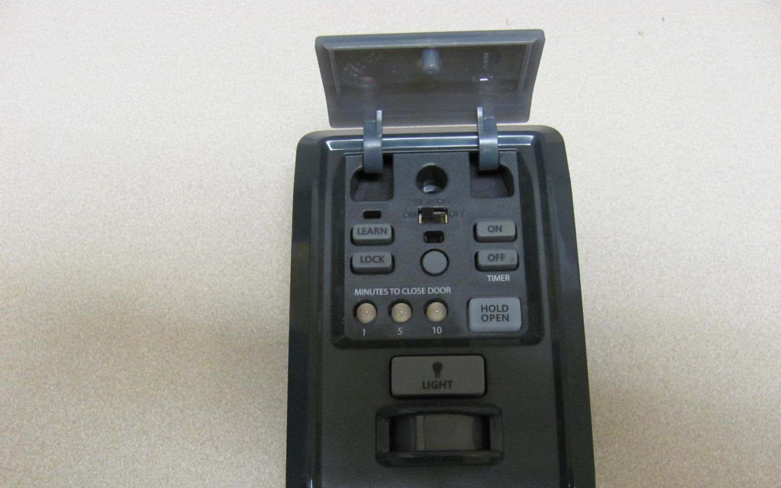
Click to zoom
Application Details
- Equipment Class
- DSS - Part 15 Spread Spectrum Transmitter
- Date of Grant
- Aug 14, 2012
- Application Purpose
- Original Equipment
- Date of Application
- Aug 14, 2012
- Equipment Note
- Part 15 Spread Spectrum Transceiver
- Frequency Range
- 902.25000000 - 926.75000000
- Company
- Chamberlain Group LLC, The
- Country
- United States
Documents & Files
Document Text
Text extracted from the exhibit documents filed with the FCC. Open a document above to read the original.
Users Manual
1 MyQ ® CONTROL PANEL MODEL 888LM To prevent possible SERIOUS INJURY or DEATH from electrocution: • Be sure power is NOT connected BEFORE installing door control. • Connect ONLY to 12-35 VOLT low voltage wires. To prevent possible SERIOUS INJURY or DEATH from a closing garage door: • Install door control within sight of garage door, out of reach of children at a minimum height of 5 feet (1.5 m), and away from ALL moving parts of door. • NEVER permit children to operate or play with door control push buttons or remote control transmitters. • Activate door ONLY when it can be seen clearly, is properly adjusted, and there are no obstructions to door travel. • ALWAYS keep garage door in sight until completely closed. NEVER permit anyone to cross path of closing garage door. • DO NOT install this door control on garage door opener systems controlling one-piece or swing doors. To provide an adequate visual alert, the garage door opener light bulb(s) MUST be a minimum of 40 Watt (or eqv.). The MyQ ® Control Panel is intended to be installed with Security✚™ Garage Door Openers manufactured between 1998 and present. The MyQ ® Control Panel is NOT compatible with Security✚ 2.0™ Garage Door Openers. DO NOT install this door control on garage door opener systems controlling one-piece or swing doors. APPLICATION The MyQ ® Control Panel offers a quick and convenient way to add Security✚ 2.0™ and MyQ ® technology to your existing garage door opener. MyQ ® technology uses a 900MHz signal to provide two-way communication between the garage door opener and MyQ ® enabled accessories. You may program up to 12 Security✚ 2.0™ remote controls, 2 Security✚ 2.0™ keyless entries and a combination of 16 MyQ ® accessories to the MyQ ® control panel. COMPATIBLE ACCESSORIES Security✚ 2.0™ Accessories:MyQ ® Accessories: Model 891LM 1- Button Remote Control Model 823LM Remote Light Switch Model 893LM 3-Button Remote Control Model 825LM Remote Light Control Model 890MAX 3-Button Mini MAX Remote Control Model 828LM LiftMaster ® Internet Gateway Model 893MAX 3-Button MAX Remote Control Model 829LM Garage Door and Gate Monitor Model 895MAX 3-Button Premium MAX Remote Control Model 877LM Wireless Keyless Entry Model 877MAX Wireless MAX Keyless Entry OVERVIEW Install the MyQ ® Control Panel in place of the existing door control. Due to power consumption the MyQ ® Control Panel cannot be used in conjunction with another wired door control connected to your garage door opener. If an additional door control is needed, the wireless door control model 885LM can be programmed to the MyQ ® Control Panel. To program the 885LM to the MyQ ® Control Panel, follow the remote control programming steps. When in battery back-up mode, any feature using unattended operation such as Timer-to-Close, close from a garage door and gate monitor or remote operation utilizing the LiftMaster ® Internet Gateway will be disabled. 1. Disconnect all electrical and battery power (if applicable) to the garage door opener. 2. Remove the existing door control from the wall. 3. Note the polarity of the wires connected to the existing door control. • Label the wire connected to the RED terminal. • Label the wire connected to the WHITE terminal. Disconnect the wires from the existing door control. 4. Connect the wires to the new MyQ ® Control Panel. Make sure the polarity is correct. • Red wire to the R terminal. • White wire to the W terminal. INSTALLATION Existing Door Control Discard, donate or recycle Wire from RED terminal Connect RED wire to R terminal Wire from WHITE terminal Connect WHITE wire to W terminal MyQ ® Control Panel 5. Mount the MyQ ® Control Panel to the wall. 6. Reconnect power. The yellow command LED and the red learn LED will blink quickly for up to 5 minutes as the control panel recharges. When the control panel is operational, the yellow command LED will glow steadily. 2 PIN ?? ? ? PROGRAMMING REMOTE CONTROL 1. Press the MyQ ® Control Panel LEARN button twice, the red learn LED will turn on. 2. Press the button on the remote control that you wish to operate your garage door. 3. The garage door opener lights will flash (or two clicks will be heard) when the code has been programmed. 1. Press the MyQ ® Control Panel LEARN button twice, the red learn LED will turn on. 2. Enter a 4-digit personal identification number (PIN) of your choice on the keyless entry keypad. Then press the ENTER button. 3. The garage door opener lights will flash (or two clicks will be heard) when the code has been programmed. KEYLESS ENTRY LEARN Button LEARN Button Model 825LM - Remote Light Control Light module can be synchronized with the garage door opener light bulbs. Model 823LM - Remote Light Switch Light module can be synchronized with the garage door opener light bulbs. LEARN Button Model 829LM - Garage Door and Gate Monitor Indicates the status of your garage door from inside the home and allows you to close an open garage door from inside the house. MyQ ® ENABLED ACCESSORIES 1. Press the MyQ ® Control Panel LEARN button twice, the red learn LED will turn on. 2. Press the LEARN button on the MyQ ® device.* * MyQ ® accessories may be programmed to the LiftMaster ® Internet Gateway (Model 828LM) or the MyQ ® control panel. For instructions on programming to the internet gateway refer to the manual. INTERNET GATEWAY The LiftMaster ® Internet Gateway gives you control of your garage door from your internet connected computer or mobile device. You must have your internet gateway registered to your customer account at www.myliftmaster.com in order to use it with the MyQ ® Control Panel. Go to www.myliftmaster.com and follow the instructions to create an account and register your device if you have not already. To program your control panel to the LiftMaster ® Internet Gateway: 1. Go to www.myliftmaster.com from a computer or mobile device. 2. Click on “Manage Places>Add New Device>Garage Door Opener” and follow the directions. 3. Once you click ADD you have 3 m…
Text truncated - open the document above for the full version.
Cover Letter(s)
845 Larch Ave. Elmhurst, IL 60126 Phone 630.993.6306 Fax 630.516.6863 Email: [email protected] August 14, 2012 Federal Communication Commission Equipment Authorization Division Application Processing Branch 7435 Oakland Mills Road Columbia, Maryland 21046 FCC ID:HBW7881 Request for Confidentiality In accordance with 47 C.F.R. Section 0.459, we, Chamberlain Group, Inc., hereby request confidentiality for the block diagram, schematic, parts list and theory of operation/technical description presented for certification. In support of the Request for Confidentiality, the following is stated: Enclosed within this application is technical information which we deem to be trade secrets and proprietary. If made public, the information might be used to our disadvantage. To assist in assuring that we receive the full value of our product and protect its competitive posture, we respectfully request this grant of confidentiality. I would appreciate your prompt attention to the submittal. If there are any questions, please call me at 630-993-6306 or send a fax to 630-516- 6863. Sincerely, Barbara Kelkhoff Regulatory Project Manager II Chamberlain Group, Inc. 845 Larch Ave. Elmhurst, IL. 60126
Test Report
For The Chamberlain Group 845 Larch Avenue Elmhurst, IL 60126 P.O. Number 4900002670 Date Tested July 25, 2012 through August 2, 2012 Test Personnel Mark Longinotti Specification FCC "Code of Federal Regulations" Title 47, Part 15, Subpart C, Sections 15.207 and 15.247 for Frequency Hopping Spread Spectrum Intentional Radiators within the band 902-928 MHz FCC “Code of Federal Regulations” Title 47, Part15, Subpart 15B, Section 15.107 and 15.109 for Receivers Industry Canada RSS-210 Industry Canada RSS-GEN Test Report By: Mark E. Longinotti EMC Engineer Approved By: Raymond J. Klouda Registered Professional Engineer of Illinois - 44894 Engineering Test Report No. 1202415-01 Measurement of RF Interference from a Firecracker Transceiver Elite Electronic Engineering Inc. 1516 Centre Circle Downers Grove, IL 60515 Tel : (630) 495-9770 Fax: (630) 495-9785 www.elitetest.com Engineering Test Report No. 1202415-01 THIS REPORT SHALL NOT BE REPRODUCED, EXCEPT IN FULL, WITHOUT THE WRITTEN APPROVAL OF ELITE ELECTRONIC ENGINEERING INCORPORATED. Page 2 of 116 TABLE OF CONTENTS PARAGRAPH DESCRIPTION OF CONTENTS PAGE NO. 1 INTRODUCTION ............................................................................................................................................... 5 1.1 Scope of Tests .......................................................................................................................................... 5 1.2 Purpose ..................................................................................................................................................... 5 1.3 Deviations, Additions and Exclusions ....................................................................................................... 5 1.4 EMC Laboratory Identification .................................................................................................................. 5 1.5 Laboratory Conditions ............................................................................................................................... 5 2 APPLICABLE DOCUMENTS ............................................................................................................................ 5 3 EUT SETUP AND OPERATION ....................................................................................................................... 6 3.1 General Description .................................................................................................................................. 6 3.1.1 Power Input .......................................................................................................................................... 6 3.1.2 Peripheral Equipment ........................................................................................................................... 6 3.1.3 Interconnect Cables ............................................................................................................................. 6 3.1.4 Grounding ............................................................................................................................................. 6 3.2 Operational Mode ..................................................................................................................................... 6 3.3 EUT Modifications ..................................................................................................................................... 6 4 TEST FACILITY AND TEST INSTRUMENTATION .......................................................................................... 7 4.1 Shielded Enclosure ................................................................................................................................... 7 4.2 Test Instrumentation ................................................................................................................................. 7 4.3 Calibration Traceability ............................................................................................................................. 7 4.4 Measurement Uncertainty ......................................................................................................................... 7 5 TEST PROCEDURES ....................................................................................................................................... 7 5.1 Receiver .................................................................................................................................................... 7 5.1.1 Powerline Conducted Emissions .......................................................................................................... 7 5.1.1.1 Requirements .............................................................................................................................. 7 5.1.1.2 Procedures .................................................................................................................................. 8 5.1.1.3 Results ......................................................................................................................................... 8 5.1.2 Radiated Measurements ...................................................................................................................... 8 5.1.2.1 Requirements .............................................................................................................................. 8 5.1.2.2 Procedures .................................................................................................................................. 9 5.1.2.3 Results ......................................................................................................................................... 9 5.2 Transmitter .............................................................................................................................................. 10 5.2.1 Powerline Conducted Emissions ..........................................................…
Text truncated - open the document above for the full version.
Test Setup Photos
Engineering Test Report No. 1202415-01 Page 20 of 116 Figure 2 Test Setup for Conducted Emissions Engineering Test Report No. 1202415-01 Page 21 of 116 Figure 3 Test Setup for Radiated Emissions – 30MHz to 1GHz, Horizontal Polarization Test Setup for Radiated Emissions – 30MHz to 1GHz, Vertical Polarization Engineering Test Report No. 1202415-01 Page 22 of 116 Figure 4 Test Setup for Radiated Emissions – 1GHz to 5GHz, Horizontal Polarization Test Setup for Radiated Emissions – 1GHz to 5GHz, Vertical Polarization
Contact Information
Applicant
Thomas DeSilvia(Director Corporate Compliance)
Technical Contact
The Chamberlain Group, Inc.Hank Sieradzki
[email protected]630-993-6564
845 Larch Ave. · Elmhurst, Illinois · United States
Test Firm
Elite Electronic Engineering Inc.Kevin Halpin
Technical Specifications
| # | Rule Parts | Frequency Range | Power Output |
|---|---|---|---|
| 1 | 15C | 902.25 MHz - 926.75 MHz | 20.00 mW |
Other Applications from Chamberlain Group LLC, The

HBW73514
Jul 06, 2026iDock Link 2
Equipment Class
DSS - Part 15 Spread Spectrum TransmitterHBW-VKP2K
Jun 23, 2026SMART GARAGE VIDEO KEYPAD
Equipment Class
DTS - Digital Transmission System
HBWCHM1
Dec 03, 2025Wireless Chime
Equipment Class
DTS - Digital Transmission SystemHBWN519
Oct 10, 2024VEHICULAR GATE OPENER
Equipment Class
DSS - Part 15 Spread Spectrum TransmitterHBWN329
Sep 22, 2024Handheld Remote
Equipment Class
DSC - Part 15 Security/Remote Control Transmitter