HBW7965Wireless Remote Control Transmitter
Chamberlain Group LLC, The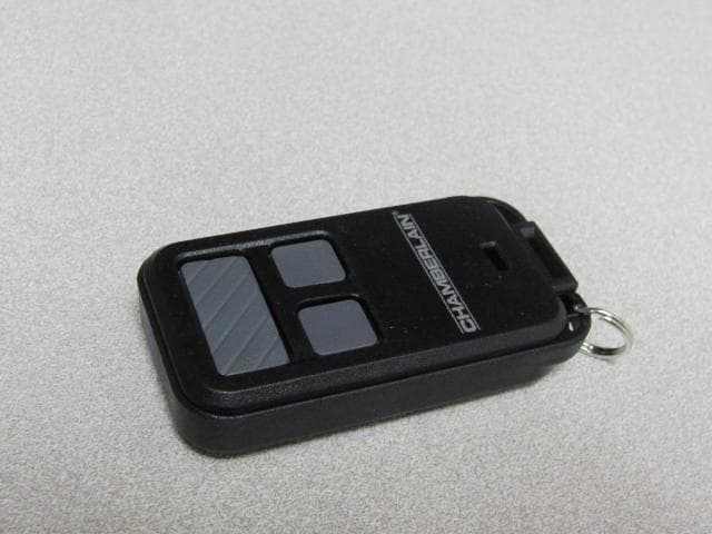
Click to zoom
Application Details
- Equipment Class
- DSC - Part 15 Security/Remote Control Transmitter
- Date of Grant
- Apr 02, 2013
- Application Purpose
- Original Equipment
- Date of Application
- Apr 02, 2013
- Equipment Note
- Wireless Remote Control Transmitter
- Frequency Range
- 310.00000000 - 390.00000000
- Company
- Chamberlain Group LLC, The
- Country
- United States
Documents & Files
Document Text
Text extracted from the exhibit documents filed with the FCC. Open a document above to read the original.
Users Manual
3-BUTTON REMOTE CONTROLS MODELS 953EV, 953EVC, 956EV AND 956EVC To prevent possible SERIOUS INJURY or DEATH from a moving gate or garage door: • ALWAYS keep remote controls out of reach of children. NEVER permit children to operate or play with remote controls. • Activate gate or door ONLY when it can be seen clearly, is properly adjusted and there are no obstructions to door travel. • ALWAYS keep gate or garage door in sight until completely closed. NEVER permit anyone to cross path of moving gate or door. For use with Chamberlain 315 MHz or 390 MHz garage door openers manufactured after January 1, 1993. The garage door opener activates when the programmed button on the remote control is pressed. The remote control can activate up to three garage door openers. Make sure the garage door opener has a working light bulb because it is a programming indicator. LED LED Locate the Program button on the remote control. Locate the Learn button on the garage door opener. NOTE: Your garage door opener may look different. OROR Learn LED Learn LED Learn LED Green or Red/Orange Purple Yellow Program Button Program Button 2 3 Press and release the remote control button you want to use... 4 To exit programming mode, press any remote control button except the button that was just programmed. Install the visor clip. 6 The garage door opener will activate. To test, press the programmed button on the remote control... 1 Press and release the Learn button on the garage door opener. Within 30 seconds... To enter programming mode, use the visor clip to press the Program button until the LED on the front of the remote control turns on. The Learn LED will light. Check to see if the garage door opener light bulb blinks. If not, wait for the remote control LED to light solid then slowly press and release the remote control button again. Repeat until the light bulb blinks. DO NOT press the button after the light bulb blinks. 5 MODELS 953EV AND 953EVCMODELS 956EV AND 956EVC GARAGE ACCESS SYSTEM REMOTE GARAGE ACCESS SYSTEM KEYCHAIN REMOTE PREPARE PROGRAM THE REMOTE CONTROL (953EV & 953EVC) 953EV & 953EVC 956EV & 956EVC 4 To exit programming mode, press any remote control button except the button that was just programmed. The garage door opener will activate. To test, press the programmed button on the remote control... Using a safety pin or paper clip, press the Program button until the LED on the front of the remote control turns on. 1 2 Press and release the Learn button on the garage door opener. Within 30 seconds... The Learn LED will light. 3 Press and release the remote control button you want to use... Check to see if the garage door opener light bulb blinks. If not, wait for the remote control LED to light solid then slowly press and release the remote control button again. Repeat until the light bulb blinks. DO NOT press the button after the light bulb blinks. 5 NOTICE: To comply with FCC and or Industry Canada rules (IC), adjustment or modifications of this receiver and/or transmitter are prohibited, except for changing the code setting or replacing the battery. THERE ARE NO OTHER USER SERVICEABLE PARTS. This device complies with Part 15 of the FCC rules and IC RSS- 210. Operation is subject to the following two conditions: (1) this device may not cause harmful interference, and (2) this device must accept any interference received, including interference that may cause undesired operation. BATTERY The LED on your remote will stop flashing when the battery is low and needs to be replaced. To replace battery, open the case as shown. Insert battery positive side up (+). Replace the battery with only 3V2032 coin cell batteries. Dispose of old battery properly. To prevent possible SERIOUS INJURY or DEATH: • NEVER allow small children near batteries. • If battery is swallowed, immediately notify doctor. To reduce risk of fire, explosion or chemical burn: • Replace ONLY with 3V2032 coin batteries. • DO NOT recharge, disassemble, heat above 212° F (100° C) or incinerate. 1-800-528-9131 114A3924C © 2013, The Chamberlain Group, Inc. All Rights Reserved REPLACEMENT PARTS Battery . . . . . . . . . . . . . . . . . . . . . . . . . . 10A20 Visor Clip (Models 953EV & 953EVC ONLY) . . . . 29B137 1 2 3 WARRANTY www.chamberlain-diy.com ONE YEAR LIMITED WARRANTY The Chamberlain Group, Inc. warrants to the first retail purchaser of this product that is free from defect in materials and/or workmanship for a period of 1 year from the date of purchase. Pry open the case with a screwdriver blade. 956EV & 956EVC Pry open the case first in the middle (1), then at each side (2 and 3) with the visor clip. 953EV & 953EVC PROGRAM THE REMOTE CONTROL (956EV & 956EVC)
Cover Letter(s)
845 Larch Ave. Elmhurst, IL 60126 Phone 630.993.6306 Fax 630.516.6863 Email: [email protected] March 18, 2013 Federal Communication Commission Equipment Authorization Division Application Processing Branch 7435 Oakland Mills Road Columbia, Maryland 21046 c.c. UL LLC. 333 Pfingsten Road Northbrook, IL 60062 To whom it may concern: I, the undersigned, hereby authorize Bart Mucha, of UL LLC, to act on our behalf in all manners relating to application for equipment authorization, including signing of all documents relating to these matters. Any and all acts carried out by Bart Mucha of UL on our behalf, shall have the same effect as acts of our own. I, the undersigned, hereby certify that we are not subject to a denial of federal benefits, that includes FCC benefits, pursuant to Section 5301 of the Anti-Drug Abuse Act of 1988, 21 U.S.C. 853(a). In authorizing UL as our agent, we still recognize that we are responsible to: a) Comply with the relevant provisions of the certification program; b) Make all necessary arrangements for the conduct of the evaluation, including provision for Examining documentation and access to all areas, records (including internal audit reports) And personnel for the purposes of evaluation (e.g. testing, inspection, assessment, surveillance, reassessment) and resolution of complaints; c) Make claims regarding certification only in respect of the scope for which certification has been granted; d) Do not use our product certification in such a manner as to bring the Certification Division Into disrepute and not make any statement regarding our product certification which the Certification Division may consider misleading or unauthorized; e) Upon suspension or cancellation of certification, discontinue use of all advertising matter That contains any reference thereto and returns any certification documents as required by the Certification Division; f) Use certification only to indicate the products are certified as being in conformity with Specified standards; g) Endeavor to ensure that no certificate or report nor any part thereof is used in a misleading manner; h) Ensure that any reference to our product certification in communication media such as documents, brochures or advertising, complies with the requirements of the Certification Division; i) Keep a record of all complaints made known to the us relating to the product’s compliance with requirements of the relevant standard and to make these records available to the Certification Division when requested; j) Take appropriate action with respect to such complaints and any deficiencies found in products or services that affect compliance with the requirements for certification; k) Document the actions taken. This authorization is valid until further written notice from the applicant. Yours sincerely, Barbara Kelkhoff Regulatory Project Manager II Chamberlain Group, Inc. 845 Larch Ave. Elmhurst, IL. 60126
Cover Letter(s)
845 Larch Ave. Elmhurst, IL 60126 Phone 630.993.6306 Fax 630.516.6863 Email: [email protected] March 18, 2013 Federal Communication Commission Equipment Authorization Division Application Processing Branch 7435 Oakland Mills Road Columbia, Maryland 21046 FCC ID: HBW7965 for circuit assembly 1D7965 Request for Confidentiality In accordance with 47 C.F.R. Section 0.457 and 0.459, we, Chamberlain Group, Inc., hereby request confidentiality for the block diagram, schematic and product description presented for certification. In support of the Request for Confidentiality, the following is stated: Enclosed within this application is technical information which we deem to be trade secrets and proprietary. If made public, the information might be used to our disadvantage. To assist in assuring that we receive the full value of our product and protect its competitive posture, we respectfully request this grant of confidentiality. I would appreciate your prompt attention to the submittal. If there are any questions, please call me at 630-993-6306 or send a fax to 630-516- 6863. Sincerely, Barbara Kelkhoff Regulatory Project Manager II Chamberlain Group, Inc. 845 Larch Ave. Elmhurst, IL. 60126
External Photos
FCC ID: HBW7965
ID Label/Location Info
FCC ID: HBW7965
ID Label/Location Info
ASSEMBLED IN MEXICO MODEL FCC ID: IC: 2666A- DATE CHAMBERLAIN GROUP INC. ELMHURST, IL 60126, USA 132C2708-2 132LA2708-20-A 1" x 1" x 0 (w x h x r) Shown at 100% ECN:05198 24-January-2011
Internal Photos
FCC ID: HBW7965
Test Report
UL LLC An organization dedicated 333 Pfingsten Rd. to public safety and committed to Northbrook, IL 60062 quality service for over 100 years Tel: (847) 272-8800 UL LLC 333 Pfingsten Rd. Northbrook, IL 60062 www.ul.com/emc (847) 272-8800 Project #: SR9617354 Order Number: 10004850 File Number: MC15343 Date: March 15, 2013 Model: 1D7965 Electromagnetic Compatibility Test Report For Chamberlain Group Inc. Copyright 2012 UL LLC UL LLC authorizes the above-named company to reproduce this Report provided it is reproduced in its entirety. Order #: 10004850 Project#: SR9617354 File #: MC15343 Page 2 of 76 Model Number: 1D7965 Client Name: Chamberlain Group Inc. UL LLC 333 Pfingsten Rd. Northbrook, IL 60062 USA Tel.: 847 272-8800 Rev. No 1.0Rev. No 1.0 EMC Report 2012-87-EM-F0042 Test Report Details Tests Performed By: UL LLC 333 Pfingsten Rd. Northbrook, IL 60062 Tests Performed For: Chamberlain Group Inc. 845 Larch Av Elmhurst, IL 60126 Applicant Contact: Hank Sieradzki Phone: (630) 993-6564 E-mail: [email protected] Test Report Date: March 15, 2013 Product Type: Universal Periodic Transmitter (Bling) Product standards FCC Part 15, Subpart C, 15.231 & RSS-210 Model Number: 1D7965 EUT Category: Wireless Device Testing Start Date: March 03, 2013 Date Testing Complete: March 05, 2013 Overall Results: Compliant UL LLC reports apply only to the specific samples tested under stated test conditions. All samples tested were in good operating condition throughout the entire test program. It is the manufacturer's responsibility to assure that additional production units of this model are manufactured with identical electrical and mechanical components. UL LLC shall have no liability for any deductions, inferences or generalizations drawn by the client or others from UL LLC issued reports. This report must not be used by the client to claim product certification, approval, or endorsement by NVLAP, NIST, any agency of the Federal Government, or any agency of any government. This report may contain test results that are not covered by the NVLAP or A2LA accreditation. The scope of accreditation is limited to the specific tests that are listed on the NVLAP and/or A2LA websites referenced at the end of this report. Order #: 10004850 Project#: SR9617354 File #: MC15343 Page 3 of 76 Model Number: 1D7965 Client Name: Chamberlain Group Inc. UL LLC 333 Pfingsten Rd. Northbrook, IL 60062 USA Tel.: 847 272-8800 Rev. No 1.0Rev. No 1.0 EMC Report 2012-87-EM-F0042 Report Directory 1.0 G E N E R A L - Product Description ..................................................................................................................5 1.1 Equipment Description ...................................................................................................................................5 1.2 Device Configuration During Test ..................................................................................................................5 1.2.1 Equipment Used During Test: ....................................................................................................................5 1.2.2 Input/Output Ports: .....................................................................................................................................5 1.2.3 Power Interface: .........................................................................................................................................5 1.3 EUT Configurations ........................................................................................................................................6 1.4 EUT Operation Modes ....................................................................................................................................6 1.5 Rational for EUT Configuration ......................................................................................................................6 2.0 Summary ............................................................................................................................................................7 2.1 Deviations from standard test methods ..........................................................................................................7 2.2 Device Modifications Necessary for Compliance ...........................................................................................7 2.3 Reference Standards .....................................................................................................................................7 2.4 Results Summary ...........................................................................................................................................7 3.0 Calibration of Equipment Used for Measurement ..............................................................................................8 4.0 EMISSIONS TEST RESULTS ............................................................................................................................8 4.1 Configuration 2 Test Data ..............................................................................................................................9 4.1.1 Test Conditions and Results – Occupied Bandwidth .................................................................................9 4.1.2 Test Conditions and Results – Cease Operation .................................................................................... 13 4.1.3 Test Conditions and Results – Pulse Train ............................................................................................. 17 4.1.4 Test Conditions and Results – RADIATED EMISSIONS Fundamental and Spurious ........................... 30 4.2 Configuration 3 Test Data ........................................................................................................................... 37 4.2.1 Test Conditions and Results – Occupied Bandwidth .............................................................................. 37 4.…
Text truncated - open the document above for the full version.
Test Setup Photos
Order #: 10004850 Project#: SR9617354 File #: MC15343 Page 74 of 76 Model Number: 1D7965 Client Name: Chamberlain Group Inc. UL LLC 333 Pfingsten Rd. Northbrook, IL 60062 USA Tel.: 847 272-8800 Rev. No 1.0Rev. No 1.0 EMC Report 2012-87-EM-F0042 Appendix B Test Setup Photos X-Axis Setup Y-Axis Setup Z-Axis setup Near Field Setup Radiated Emissions setup
Contact Information
Applicant
Thomas DeSilvia(Director Corporate Compliance)
Test Firm
UL LLCRick Titus
Technical Specifications
| # | Rule Parts | Frequency Range | Power Output |
|---|---|---|---|
| 1 | 15.231 | 310 MHz - 390 MHz | - |
Other Applications from Chamberlain Group LLC, The

HBW73514
Jul 06, 2026iDock Link 2
Equipment Class
DSS - Part 15 Spread Spectrum TransmitterHBW-VKP2K
Jun 23, 2026SMART GARAGE VIDEO KEYPAD
Equipment Class
DTS - Digital Transmission System
HBWCHM1
Dec 03, 2025Wireless Chime
Equipment Class
DTS - Digital Transmission SystemHBWN519
Oct 10, 2024VEHICULAR GATE OPENER
Equipment Class
DSS - Part 15 Spread Spectrum TransmitterHBWN329
Sep 22, 2024Handheld Remote
Equipment Class
DSC - Part 15 Security/Remote Control Transmitter