HBWAAO61-2115
Chamberlain Group LLC, The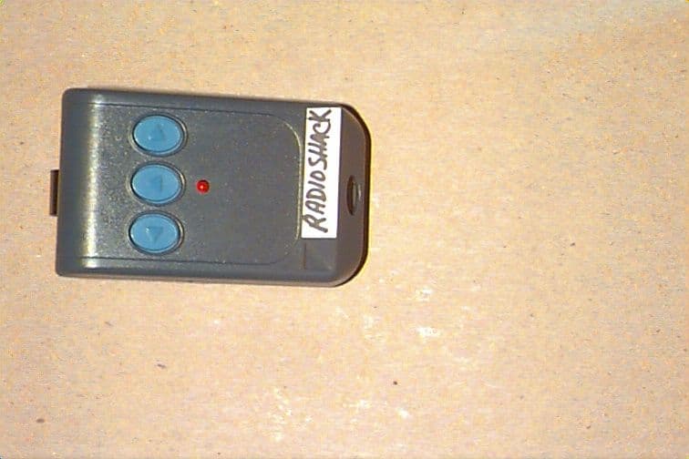
Click to zoom
Application Details
- Equipment Class
- DSC - Part 15 Security/Remote Control Transmitter
- Date of Grant
- Aug 23, 1999
- Application Purpose
- Original Equipment
- Date of Application
- Jun 22, 1999
- Frequency Range
- 390.00000000 - 390.00000000
- Company
- Chamberlain Group LLC, The
- Country
- United States
Documents & Files
Document Text
Text extracted from the exhibit documents filed with the FCC. Open a document above to read the original.
Cover Letter(s)
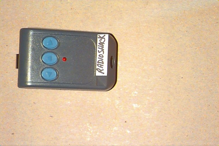
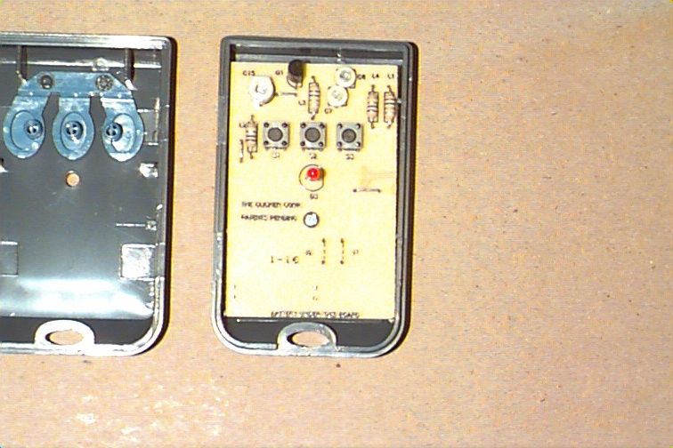
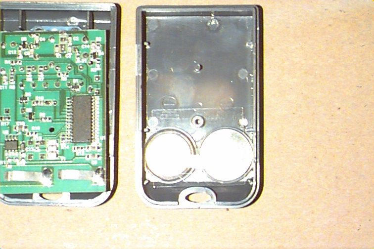
845 Larch Ave. Elmhurst, IL 60126 phone 630.993.6306 fax 630.530.6140 email: [email protected] June 23, 1999 Federal Communications Commission EQUIPMENT APPROVAL SERVICES PO Box 358315 Pittsburgh, PA 15251-5315 Re: Request for Certification Enclosed is an application, fee in the amount of $940, and exhibits for Certification of a Remote Control Transmitter, Cat.No.61-2115, which is manufactured by Chamberlain for Radio Shack. The final instruction sheet is not available at this time, so I have included a typical instruction sheet indicating the FCC statement and important information. The FCC ID of this model, upon certification, will be AAO61-2115. We would appreciate your prompt attention to the submittal. Sincerely, THE CHAMBERLAIN GROUP, INC. Barbara P. Kelkhoff Manager, Product Safety LIST OF EXHIBITS 3 FUNCTION, REMOTE CONTROL TRANSMITTER Cat. No. 61-2115 1. Expository Statement 2. Theory of Operation 3. Schematic 4. Photographs 5. FCC Label Drawing 6. Operating Instructions 7. Test Report EXPOSITORY STATEMENT 3 FUNCTION, REMOTE CONTROL TRANSMITTER Cat. No. 61-2115 1. Since the final instruction sheet is not available at this time, a typical draft version has been included. The instructions include statements required to assure compliance with the Commission's Rules; Part 15. 2. Labeling is in accordance with the Commission's labeling requirements, Parts 2 and 15, Section 15.19. 3. This transmitter is intended for use with the certified receivers of garage door and gate operator systems manufactured by Chamberlain , Genie , and Linear . 4. The transmitter is equipped with an automatically releasing push-button switch. Transmission is terminated upon release of the push-button. 5. The Cat.No.61-2115 transmitter is factory set to 300, 310, and 390 ± 0.1% MHz.. It is not intended to be readjusted in the field, and specific instructions prohibiting tampering are provided to the user. 6. Test data for Model RS321, which is identical to Cat. No. 61-2115, is part of this submission. No emissions were detected in the forbidden bands below 1.0 GHz. Certified by: Barbara P. Kelkhoff Manager, Product Safety UNIVERSAL TRANSMITTER CIRCUIT DESCRIPTION FOR CAT. NO. 61-2115 I. Overview The Universal Transmitter is a unique combination of circuits which attains compatibility with most garage door openers by means of a programmable micro controller with non- volatile memory and a radiating oscillator with frequency selectable by logic controlled pin diode switching. II. Detailed Description (Refer to Block Diagram and Schematic) RF Circuit -The transmit oscillator actually generates the RF energy which conveys the code information to the receiver. Q1 is the active transistor element of the oscillator. Fixed capacitors C1- C5, tuning capacitors C6, C7, C16, and a PC Trace Inductive Radiating Element are the frequency- determining parts and are configured as a pi-network feedback circuit. L1 choke conveys battery power to the oscillator, and R1 provides base current to Q1 to turn the oscillator on and off in accordance with the code output from the micro controller. Pin diodes, D4 and D5, switch the tuning capacitors depending on the desired frequency (see Frequency Select Logic Table on Block Diagram). L3, L4, and L5 provide ac isolation between the logic and RF, and R2-R5 provide forward and reverse biasing for the pin diodes. C12 and C14 are dc blocking capacitors that provide an RF circuit short. Micro controller - U1 is an 8-bit micro controller which in addition to program memory and RAM also contains a small amount of EEPROM. This combination allows code that is field programmable and non-volatile. The micro timing is based on an on-board oscillator with an external 4 MHz ceramic resonator, Y1. R13 and C8 form the reset timing circuit. The micro controller provides the code output, the frequency logic, the LED drive, and powers the latch that keeps the power on once a switch push is detected. Switches, Latch, and Regulator - The regulator, U2, is a low-drop type at 4.75 volts which allows the micro voltage to remain in regulation for the useful life of the 2 cell, 6 volt lithium battery source. U2 also contains an electronic power switch, which along with the micro, R9, and Q2 forms the latch that keeps the power on when required. R6-R8, D1, D2, and micro pins PC1-PC5 form the circuits which detect the switch activation. The pushbutton switches, S1-S3, perform programming and transmit select functions (see programming description below). The 3 switches mean that the transmitter is capable of 3-channel operation. The red LED, D3, and the associated current limit resistor, R10, allows visual feedback for transmit indication and programming aid. 1. EXPOSITORY STATEMENT 2. THEORY OF OPERATION 3. SCHEMATIC 4. PHOTOGRAPHS 5. FCC LABEL DRAWING 6. OPERATING INSTRUCTIONS 7. TEST REPORT
Cover Letter(s)
845 Larch Ave. Elmhurst, IL 60126 phone 630.993.6306 fax 630.530.6140 email: [email protected] July 1, 1999 Federal Communications Commission EQUIPMENT APPROVAL SERVICES PO Box 358315 Pittsburgh, PA 15251-5315 Re: EA94626 Grantee Code Correction The FCC identifier shown on the 731 application form is not correct.The correct Grantee Code for this application is: AAO. The FCC ID of this model, upon certification, will be AAO61-2115. Chamberlain is the manufacturer and an agent for Radio Shack. Please add the two items shown below to the form 731 that was submitted with this application. Item 5. Instead of applicant, FCC is authorized to mail grant to: Chamberlain Group Inc., 845 Larch Ave., Elmhurst, IL.60126. The person to receive the grant is: Barbara Kelkhoff, Manager, Product Safety and Reliability. E-mail address is: [email protected]. Item 6. Technical contact is Barbara Kelkhoff, Manager, Product Safety and Reliability at The Chamberlain Group Inc., 845 Larch Ave., Elmhurst, IL.60126. We would appreciate your prompt attention to the submittal. Sincerely, THE CHAMBERLAIN GROUP, INC. Barbara P. Kelkhoff Manager, Product Safety
Cover Letter(s)
845 Larch Ave. Elmhurst, IL 60126 phone 630.993.6306 fax 630.530.6140 email: [email protected] July 1, 1999 Federal Communications Commission EQUIPMENT APPROVAL SERVICES PO Box 358315 Pittsburgh, PA 15251-5315 Re: EA94626 Grantee Code Correction The FCC identifier shown on the 731 application form is not correct.The correct Grantee Code for this application is: AAO. The FCC ID of this model, upon certification, will be AAO61-2115. Chamberlain is the manufacturer and an agent for Radio Shack. Please add the two items shown below to the form 731 that was submitted with this application. Item 5. Instead of applicant, FCC is authorized to mail grant to: Chamberlain Group Inc., 845 Larch Ave., Elmhurst, IL.60126. The person to receive the grant is: Barbara Kelkhoff, Manager, Product Safety and Reliability. E-mail address is: [email protected]. Item 6. Technical contact is Barbara Kelkhoff, Manager, Product Safety and Reliability at The Chamberlain Group Inc., 845 Larch Ave., Elmhurst, IL.60126. We would appreciate your prompt attention to the submittal. Sincerely, THE CHAMBERLAIN GROUP, INC. Barbara P. Kelkhoff Manager, Product Safety
Cover Letter(s)
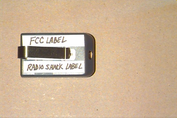
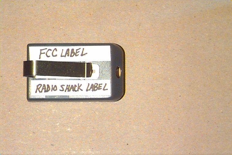
845 Larch Ave. Elmhurst, IL 60126 phone 630.993.6306 fax 630.530.6140 email: [email protected] July 13, 1999 Federal Communications Commission EQUIPMENT APPROVAL SERVICES PO Box 358315 Pittsburgh, PA 15251-5315 Re: EA94626, Ref. No. 8683 Correct Grantee Code This request follows Hank's discussion with Betty Taube on July 8, 1999 concerning the solution to the problem of receiving of the grant of authorization. We would like to list Chamberlain as the manufacturer and the responsible party for Radio Shack. The 731 form information is correct as originally submitted on June 23, 1999. The FCC ID of this model, upon certification, will be HBWAAO61-2115. I have also attached the photographs of the identification and location of the label as originally submitted on June 23, 1999. Please proceed with the processing of this application. Sincerely, THE CHAMBERLAIN GROUP, INC. Barbara P. Kelkhoff Manager, Product Safety
Cover Letter(s)
845 Larch Ave. Elmhurst, IL 60126 phone 630.993.6306 fax 630.530.6140 email: [email protected] July 19, 1999 Federal Communications Commission EQUIPMENT APPROVAL SERVICES PO Box 358315 Pittsburgh, PA 15251-5315 Re: EA94626 Label size Since there is no engineer assigned to this job, I spoke to Mr. Errol Chang of your FCC office regarding my label size problem. He suggested that I explain it in a letter and submit it as an attachment. The original submission, June 23 rd , EA94626, showed two labels, each 3/8"x 2 3/16", on the rear of the transmitter. We are limited to that size because of the printable area. The intent was that one label includes the manufacturer information and the other label includes all of the FCC Part 15 information. After trying to create the artwork for this label, we discovered that we cannot fit all of the FCC Part 15 information on the back of the transmitter. We would like to put the FCC Part 15 statement in the owner's manual. So we would like to submit for FCC Certification with the following. 1. Attachment 1: Manufacturer information with FCC ID that we intend to use on the transmitter. 2. Attachment 2: FCC label that does not fit. This statement will be in owner's manual. 3. Attachment 3: FCC label position and location on transmitter. 4. Attachment 4: New instructions page showing FCC statement. If you have any questions, please contact me at 630-993-6564 or E mail me at [email protected]. Sincerely, THE CHAMBERLAIN GROUP, INC. Hank Sieradzki Regulatory Engineer
ID Label/Location Info
( 3/8" x 2 13/16 " ) RadioShack Cat. No. 61-2115 Requires CR2025 Battery (Cat. No. 23-161) Custom Mfd. In Mexico for RadioShack A Division of Tandy Corp., Fort Worth, Tx.76102 ( 3/8" x 2 13/16 " ) This device complies with part 15 of the FCC rules. Operation is subject to the following two conditions:(1) This device may not cause harmful interference, and (2) This device must accept any interference that may be received, including interference that may cause undesired operation. Frequency 300,310,390 MHz Radio Shack Cat. No. 61-2115 Transmitter labels Garage Door / Gate Remote Control FCC ID: AAO61-2115
ID Label/Location Info
( 3/8" x 2 3/16 " ) RadioShack Cat. No. 61-2115 Requires CR2025 Battery (Cat. No. 23-161) Custom Mfd. In Mexico for RadioShack A Division of Tandy Corp., Fort Worth, Tx.76102 ( 3/8" x 2 3/16 " ) This device complies with part 15 of the FCC rules. Operation is subject to the following two conditions:(1) This device may not cause harmful interference, and (2) This device must accept any interference that may be received, including interference that may cause undesired operation. Frequency 300,310,390 MHz Radio Shack Cat. No. 61-2115 Transmitter labels Garage Door / Gate Remote Control FCC ID: HBWAAO61-2115
Operational Description
845 Larch Ave. Elmhurst, IL 60126 phone 630.993.6306 fax 630.530.6140 email: [email protected] June 23, 1999 Federal Communications Commission EQUIPMENT APPROVAL SERVICES PO Box 358315 Pittsburgh, PA 15251-5315 Re: Request for Certification Enclosed is an application, fee in the amount of $940, and exhibits for Certification of a Remote Control Transmitter, Cat.No.61-2115, which is manufactured by Chamberlain for Radio Shack. The final instruction sheet is not available at this time, so I have included a typical instruction sheet indicating the FCC statement and important information. The FCC ID of this model, upon certification, will be AAO61-2115. We would appreciate your prompt attention to the submittal. Sincerely, THE CHAMBERLAIN GROUP, INC. Barbara P. Kelkhoff Manager, Product Safety LIST OF EXHIBITS 3 FUNCTION, REMOTE CONTROL TRANSMITTER Cat. No. 61-2115 1. Expository Statement 2. Theory of Operation 3. Schematic 4. Photographs 5. FCC Label Drawing 6. Operating Instructions 7. Test Report EXPOSITORY STATEMENT 3 FUNCTION, REMOTE CONTROL TRANSMITTER Cat. No. 61-2115 1. Since the final instruction sheet is not available at this time, a typical draft version has been included. The instructions include statements required to assure compliance with the Commission's Rules; Part 15. 2. Labeling is in accordance with the Commission's labeling requirements, Parts 2 and 15, Section 15.19. 3. This transmitter is intended for use with the certified receivers of garage door and gate operator systems manufactured by Chamberlain , Genie , and Linear . 4. The transmitter is equipped with an automatically releasing push-button switch. Transmission is terminated upon release of the push-button. 5. The Cat.No.61-2115 transmitter is factory set to 300, 310, and 390 ± 0.1% MHz.. It is not intended to be readjusted in the field, and specific instructions prohibiting tampering are provided to the user. 6. Test data for Model RS321, which is identical to Cat. No. 61-2115, is part of this submission. No emissions were detected in the forbidden bands below 1.0 GHz. Certified by: Barbara P. Kelkhoff Manager, Product Safety UNIVERSAL TRANSMITTER CIRCUIT DESCRIPTION FOR CAT. NO. 61-2115 I. Overview The Universal Transmitter is a unique combination of circuits which attains compatibility with most garage door openers by means of a programmable micro controller with non- volatile memory and a radiating oscillator with frequency selectable by logic controlled pin diode switching. II. Detailed Description (Refer to Block Diagram and Schematic) RF Circuit -The transmit oscillator actually generates the RF energy which conveys the code information to the receiver. Q1 is the active transistor element of the oscillator. Fixed capacitors C1- C5, tuning capacitors C6, C7, C16, and a PC Trace Inductive Radiating Element are the frequency- determining parts and are configured as a pi-network feedback circuit. L1 choke conveys battery power to the oscillator, and R1 provides base current to Q1 to turn the oscillator on and off in accordance with the code output from the micro controller. Pin diodes, D4 and D5, switch the tuning capacitors depending on the desired frequency (see Frequency Select Logic Table on Block Diagram). L3, L4, and L5 provide ac isolation between the logic and RF, and R2-R5 provide forward and reverse biasing for the pin diodes. C12 and C14 are dc blocking capacitors that provide an RF circuit short. Micro controller - U1 is an 8-bit micro controller which in addition to program memory and RAM also contains a small amount of EEPROM. This combination allows code that is field programmable and non-volatile. The micro timing is based on an on-board oscillator with an external 4 MHz ceramic resonator, Y1. R13 and C8 form the reset timing circuit. The micro controller provides the code output, the frequency logic, the LED drive, and powers the latch that keeps the power on once a switch push is detected. Switches, Latch, and Regulator - The regulator, U2, is a low-drop type at 4.75 volts which allows the micro voltage to remain in regulation for the useful life of the 2 cell, 6 volt lithium battery source. U2 also contains an electronic power switch, which along with the micro, R9, and Q2 forms the latch that keeps the power on when required. R6-R8, D1, D2, and micro pins PC1-PC5 form the circuits which detect the switch activation. The pushbutton switches, S1-S3, perform programming and transmit select functions (see programming description below). The 3 switches mean that the transmitter is capable of 3-channel operation. The red LED, D3, and the associated current limit resistor, R10, allows visual feedback for transmit indication and programming aid. 1. EXPOSITORY STATEMENT 2. THEORY OF OPERATION 3. SCHEMATIC 4. PHOTOGRAPHS 5. FCC LABEL DRAWING 6. OPERATING INSTRUCTIONS 7. TEST REPORT
Test Report
TÜV PRODUCT SERVICE 10040 Mesa Rim Road San Diego, CA 92121-2912 Phone 619 546 3999 FAX 619 546 0364 Report No. 9264-06 Page 1 of 11 Rev.No 1.0 EMC EMISSION - TEST REPORT UNITED STATES STANDARD 47 CFR PART 15, SUBPART B Test Report File No.: 9264-06 Date of Issue: 08 June 1999 Model / Serial No.: RS321 / ---- Product Type: Handheld Transmitter Applicant:RADIO SHACK Manufacturer:RADIO SHACK License holder:RADIO SHACK Address:100 Throckmorton Street, Suite 1300 :Fort Worth, TX 76102 Test Result: nn Positiveoo Negative Test Project Number Reference(s): 9264-06 Total pages - Test Report:11 NOTE: All test equipment used during testing is calibrated and traceable to NIST. TÜV Product Service reports apply only to the specific sample tested under stated test conditions. It is the manufacturer’s responsibility to assure the continued compliance of production units of this model. TÜV Product Service, Inc. shall have no liability for any deductions, inferences or generalizations drawn by the client or others from TÜV Product Service, Inc. issued reports. This report is the confidential property of the client. As a mutual protection to our clients, the public and ourselves, extracts from the test report shall not be reproduced except in full without our written approval. This report shall not be used by the client to claim product endorsement by NVLAP or any agency of the US government. TÜV Product Service, Inc. and its professional staff hold government and professional organization certifications and are members of AAMI, ACIL, AEA, ANSI, IEEE, NVLAP, and VCCI TÜV PRODUCT SERVICE 10040 Mesa Rim Road San Diego, CA 92121-2912 Phone 619 546 3999 FAX 619 546 0364 Report No. 9264-06 Page 2 of 11 Rev.No 1.0 DIRECTORY - EMISSIONS Test Report Pages Test Report1 - 11 Directory2 Test Regulations3 General Remarks and Summary11 Equipment Conducted Emissions5 Radiated Emissions30 - 1000 MHz6 20 dB Bandwidth7 Radiated Emissions300 - 1200 MHz8 Duty Cycle9 Technical Documentation Test Data Sheets and Test Setup Drawing(s)TD1 Appendices Appendix A A1 Test Setups (Photographs) Appendix B B1 Product Information Form(s) Appendix C C1 Change History Appendix D D1 Supplemental Information TÜV PRODUCT SERVICE 10040 Mesa Rim Road San Diego, CA 92121-2912 Phone 619 546 3999 FAX 619 546 0364 Report No. 9264-06 Page 3 of 11 Rev.No 1.0 EMISSIONS TEST REGULATIONS : The emissions tests were performed according to the following regulations: o - EN 50081-1 / 1991 o - EN 55011 / 1991o - Group 1o - Group 2 o - Class Ao - Class B o - EN 55013 / 1990 o - EN 55014 / 1987o - Household appliances and similar o - Portable tools o - Semiconductor devices o - EN 55014 / A2:1990 o - EN 55014 / 1993o - Household appliances and similar o - Portable tools o - Semiconductor devices o - EN 55015 / 1987 o - EN 55015 / A1:1990 o - EN 55015 / 1993 o - EN 55022 / 1987o - Class Ao - Class B o - EN 55022 / 1998o - Class Ao - Class B o - BS o - VCCIo - Class A ITEo - Class B ITE n - 47 CFR Part 15, Subpart B n - 207(a) n - 209(a) n - 231(b)(c) n - Duty cycle o - AS/NZS 3548: 1995o - Class Ao - Class B o - CISPR 11 (1990) o - Group 1o - Group 2 o - Class Ao - Class B o - CISPR 22 (1998) o - Class Ao - Class B TÜV PRODUCT SERVICE 10040 Mesa Rim Road San Diego, CA 92121-2912 Phone 619 546 3999 FAX 619 546 0364 Report No. 9264-06 Page 4 of 11 Rev.No 1.0 Environmental Conditions In The Laboratory: Actual Temperature:: 23 °C Relative Humidity:: 50 % Atmospheric Pressure:: 100.0 kPa Power Supply Utilized: Power supply system: Battery Symbol Definitions: n -Applicable o -Not Applicable TÜV PRODUCT SERVICE 10040 Mesa Rim Road San Diego, CA 92121-2912 Phone 619 546 3999 FAX 619 546 0364 Report No. 9264-06 Page 5 of 11 Rev.No 1.0 Emissions Test Conditions: CONDUCTED EMISSIONS (Interference Voltage) The CONDUCTED EMISSIONS (INTERFERENCE VOLTAGE) measurements were performed at the following test location: n - Test not performed - see remarks o - SR-2, Shielded Room, 12’ x 24’ x 10’, Metal Chamber o - SR-3, Shielded Room, 12’ x 20’ x 8’, Metal Chamber o - SR-4, Shielded Room, 10’ x 17’ x 8’, Copper Screen Chamber o - SR-5, Shielded Room, 16’ x 28’ x 15’, Metal, Semi-Anechoic Chamber o - CSR-1, Shielded Room, 10’ x 7’ x 7’, Metal Chamber Test Equipment Used : Model No.Prop. No.DescriptionManufacturerSerial No.Cal Due Date NM-7A, NM-17/27, NM-37/57, NM-67, CCA-7, & H/P 9836 HP-1B Computer 156, 162-166 Automated RFI Measurement System (ARMS), NO. 1 Eaton/Ailtech(multiple) NM-17/27, NM-37/57, CA-7, and H/P 9826 Computer 168, 170, 177, 178 Automated RFI Measurement System (ARMS), NO. 2 Eaton/Ailtech(multiple) H/P Spectrum Analyzer, Model 8568B; Display Section RF Analyzer Section; H/P 85650A, Quasi-Peak Adapter H/P Computer System, Model 310 with HP 85869A Software 187, 188Automated RFI Measurement System (ARMS) Various(multiple) LISN-2, 25 A413Power Mains Network (LISN), 50 μH/250 μH/50 Ω/0.25 μF Fischer Custom Communications, Inc. 7 LISN-2, 25 A--Power Mains Network (LISN), 50 μH/250 μH/50 Ω/0.25 μF Fischer Custom Communications, Inc. 7 FCC-LISN-50-25-2553Power Mains Network (LISN), 50 μH/250 μH/50 Ω/0.25 μF Fischer Custom Communications, Inc. 112 FCC-LISN-50-25-2552Power Mains Network (LISN), 50 μH/250 μH/50 Ω/0.25 μF Fischer Custom Communications, Inc. 113 8012-50-R-12-BNC266 LISN, 50 μH/50 Ω/0.1 μF Solar Electronics Co.-- 9252-50-R-24-BNC458 LISN, 50 μH /250 μH/50 Ω/ 0.25 μF Solar Electronics Co.941719 MDS-21277Absorbing ClampRohde & Schwarz821023 ESHS 20428EMI Test ReceiverRohde & Schwarz837055/001 ESHS 30459EMI Test ReceiverRohde & Schwarz832354/004 CAT-2059820 dB AttenuatorMini-Circuits-- CAT-2061520 dB AttenuatorMini-Circuits-- Remarks: One year calibration cycle for all test equipment. EUT battery operated. TÜV PRODUCT SERVICE 10040 Mesa Rim Road San Diego, CA 92121-2912 Phone 619 546 3999 FAX 619 546 0364 Report No. 9264-06 Page 6 of 11 Rev.No 1.0 Emissions Test Conditions: RADIATED EMISSIONS (Electric Field) The RADIATED EMISSIONS (ELECTRIC FIELD) measuremen…
Text truncated - open the document above for the full version.
Contact Information
Applicant
Thomas DeSilvia(Director Corporate Compliance)
Technical Specifications
| # | Rule Parts | Frequency Range | Power Output | Tolerance |
|---|---|---|---|---|
| 3 | 15C | 390 MHz - 390 MHz | - | % |
Other Applications from Chamberlain Group LLC, The

HBW73514
Jul 06, 2026iDock Link 2
Equipment Class
DSS - Part 15 Spread Spectrum TransmitterHBW-VKP2K
Jun 23, 2026SMART GARAGE VIDEO KEYPAD
Equipment Class
DTS - Digital Transmission System
HBWCHM1
Dec 03, 2025Wireless Chime
Equipment Class
DTS - Digital Transmission SystemHBWN519
Oct 10, 2024VEHICULAR GATE OPENER
Equipment Class
DSS - Part 15 Spread Spectrum TransmitterHBWN329
Sep 22, 2024Handheld Remote
Equipment Class
DSC - Part 15 Security/Remote Control Transmitter