HBWTCTX120Garage Door Remote Control
Chamberlain Group LLC, The
Click to zoom
Application Details
- Equipment Class
- DSC - Part 15 Security/Remote Control Transmitter
- Date of Grant
- Nov 28, 1999
- Application Purpose
- Original Equipment
- Date of Application
- Nov 11, 1999
- Equipment Note
- Garage Door Remote Control
- Frequency Range
- 390.00000000 - 390.00000000
- Company
- Chamberlain Group LLC, The
- Country
- United States
Documents & Files

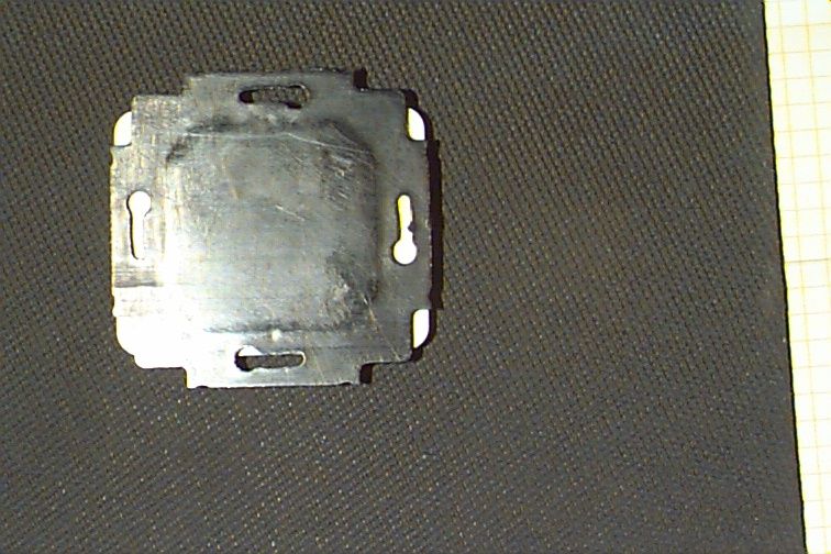
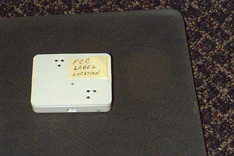

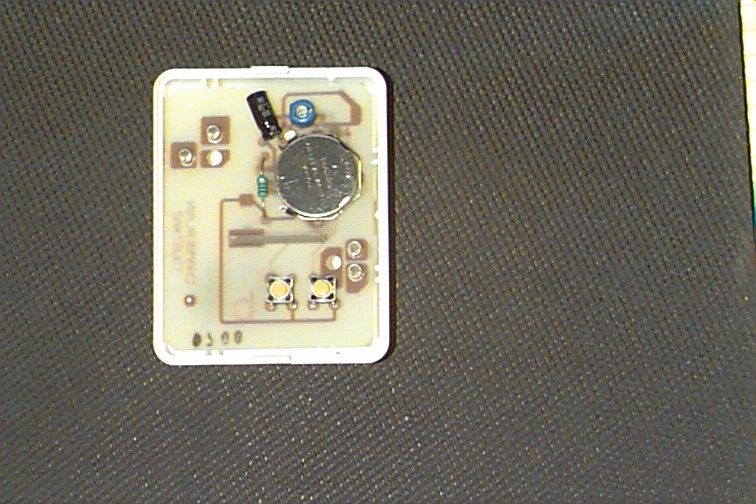
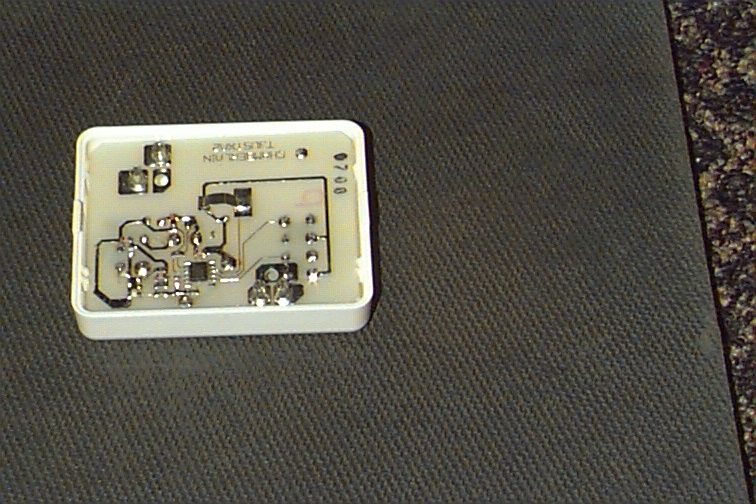
Document Text
Text extracted from the exhibit documents filed with the FCC. Open a document above to read the original.
Cover Letter(s)
845 Larch Ave. Elmhurst, IL 60126 Phone 630.993.6306 Fax 630.530.6140 Email: [email protected] November 12, 1999 Federal Communications Commission EQUIPMENT APPROVAL SERVICES PO Box 358315 Pittsburgh, PA 15251-5315 Re: Request for Certification Enclosed is an application, fee in the amount of $895, and exhibits for Certification of a Remote Control Transmitter, Model TCTX120. The final instruction sheet is not available at this time, so I have included a typical instruction sheet indicating the FCC statement and important information. The FCC ID of this model, upon certification, will be HBWTCTX120. We would appreciate your prompt attention to the submittal. Sincerely, THE CHAMBERLAIN GROUP, INC. Barbara P. Kelkhoff Manager, Product Safety LIST OF EXHIBITS 2 FUNCTION, REMOTE CONTROL TRANSMITTER MODEL TCTX120 1. Expository Statement 2. Theory of Operation 3. Schematic 4. Photographs 5. FCC Label Drawing 6. Operating Instructions 7. Test Report EXPOSITORY STATEMENT 3 FUNCTION, REMOTE CONTROL TRANSMITTER MODEL TCTX120 1. Since the final instruction sheet is not available at this time, a marked-up typical version has been included. The instructions include statements required to assure compliance with the Commission's Rules; Part 15. 2. Labeling is in accordance with the Commission's labeling requirements, Parts 2 and 15, Section 15.19. 3. This transmitter is intended for use with the certified receivers of our manufacture only. 4. The transmitter is equipped with an automatically releasing push-button switch. Transmission is terminated upon release of the push-button. 5. The TCTX120 is factory set to 390 ± 0.1% MHz. It is not intended to be readjusted in the field, and specific instructions prohibiting tampering are provided to the user. 6. Test data for the Model TCTX120 is part of this submission. No emissions were detected in the forbidden bands below 1.0GHz. Certified by: Barbara P. Kelkhoff Manager, Product Safety THEORY OF OPERATION AND CIRCUIT DESCRIPTION MODEL TCTX120 2 FUNCTION, REMOTE CONTROL TRANSMITTER (Please refer to enclosed schematic drawing) The TCTX120 transmitter consists of a low power RF oscillator which doubles as a square-law detector (Q2 and associated components), a digital encoder (U1 and associated components), a switch-mode boost voltage converter (L1, Q1, and associated components), and on/off switches. The RF oscillator, Q2, is of the grounded base type. C6, C7, C8, C9, and the copper loop set the center frequency of the oscillator at 390 MHz. C4 and C5, along with the internal capacitance of Q2, establish feedback levels and harmonic suppression. R5 and R6 establish dc operating conditions. U1 and related components generate a digital code. This code is used in the companion receiver to identify a particular transmitter or function. When transmitting a radio code, the unit generates a 9 volt power supply for the RF circuit from its 3V source through the switching voltage converter formed by L1, Q1, and associated components. Q1 is periodically switched on, causing current to flow through L1 at a rate, which increases linearly. When Q1 is switched off, a high voltage is generated across L1 due to the instantaneous change in inductor current. This voltage is transferred across D1 and stored in C2. 1. EXPOSITORY STATEMENT 2. THEORY OF OPERATION 3. SCHEMATIC 4. PHOTOGRAPHS 5. FCC LABEL DRAWING 6. OPERATING INSTRUCTIONS 7. TEST REPORT
ID Label/Location Info
ASSEMBLED IN MEXICO CANADA FCC ID: DATE CHAMBERLAIN GROUP INC. ELMHURST, IL 60126, USA Shown at 200% 132LA2000-10-D ECN: H-201 This device complies with Part 15 of theFCC Rules. Operation is subject to thefollowing two conditions: (1) this device maynot cause harmful interference, and (2) thisdevice must accept any interferencereceived, including interference that maycause undesired operation. 132C2000-1
Operational Description
845 Larch Ave. Elmhurst, IL 60126 Phone 630.993.6306 Fax 630.530.6140 Email: [email protected] November 12, 1999 Federal Communications Commission EQUIPMENT APPROVAL SERVICES PO Box 358315 Pittsburgh, PA 15251-5315 Re: Request for Certification Enclosed is an application, fee in the amount of $895, and exhibits for Certification of a Remote Control Transmitter, Model TCTX120. The final instruction sheet is not available at this time, so I have included a typical instruction sheet indicating the FCC statement and important information. The FCC ID of this model, upon certification, will be HBWTCTX120. We would appreciate your prompt attention to the submittal. Sincerely, THE CHAMBERLAIN GROUP, INC. Barbara P. Kelkhoff Manager, Product Safety LIST OF EXHIBITS 2 FUNCTION, REMOTE CONTROL TRANSMITTER MODEL TCTX120 1. Expository Statement 2. Theory of Operation 3. Schematic 4. Photographs 5. FCC Label Drawing 6. Operating Instructions 7. Test Report EXPOSITORY STATEMENT 3 FUNCTION, REMOTE CONTROL TRANSMITTER MODEL TCTX120 1. Since the final instruction sheet is not available at this time, a marked-up typical version has been included. The instructions include statements required to assure compliance with the Commission's Rules; Part 15. 2. Labeling is in accordance with the Commission's labeling requirements, Parts 2 and 15, Section 15.19. 3. This transmitter is intended for use with the certified receivers of our manufacture only. 4. The transmitter is equipped with an automatically releasing push-button switch. Transmission is terminated upon release of the push-button. 5. The TCTX120 is factory set to 390 ± 0.1% MHz. It is not intended to be readjusted in the field, and specific instructions prohibiting tampering are provided to the user. 6. Test data for the Model TCTX120 is part of this submission. No emissions were detected in the forbidden bands below 1.0GHz. Certified by: Barbara P. Kelkhoff Manager, Product Safety THEORY OF OPERATION AND CIRCUIT DESCRIPTION MODEL TCTX120 2 FUNCTION, REMOTE CONTROL TRANSMITTER (Please refer to enclosed schematic drawing) The TCTX120 transmitter consists of a low power RF oscillator which doubles as a square-law detector (Q2 and associated components), a digital encoder (U1 and associated components), a switch-mode boost voltage converter (L1, Q1, and associated components), and on/off switches. The RF oscillator, Q2, is of the grounded base type. C6, C7, C8, C9, and the copper loop set the center frequency of the oscillator at 390 MHz. C4 and C5, along with the internal capacitance of Q2, establish feedback levels and harmonic suppression. R5 and R6 establish dc operating conditions. U1 and related components generate a digital code. This code is used in the companion receiver to identify a particular transmitter or function. When transmitting a radio code, the unit generates a 9 volt power supply for the RF circuit from its 3V source through the switching voltage converter formed by L1, Q1, and associated components. Q1 is periodically switched on, causing current to flow through L1 at a rate, which increases linearly. When Q1 is switched off, a high voltage is generated across L1 due to the instantaneous change in inductor current. This voltage is transferred across D1 and stored in C2. 1. EXPOSITORY STATEMENT 2. THEORY OF OPERATION 3. SCHEMATIC 4. PHOTOGRAPHS 5. FCC LABEL DRAWING 6. OPERATING INSTRUCTIONS 7. TEST REPORT
Schematics
CHAMBERLAIN SPEC NO 190Axxxx Tubular Motor Wall Mounted 390Mhz transmitter design Specification PAGE 1 of 3 ECN# DATE BY APPVD REVISION ISSUE 4/13/99srtRev 00 PURPOSE This specification defines the design parameters of the Billion code Tubular motor 120V wall mountable transmitter. This transmitter uses the CGI rolling code transmitter chip, P/N 125C0130 programmed for fixed, billion-code operation. II.GENERAL CRITERIA A. Description: The device is a wall mountable transmitter designed for use with the TM 120V receiver. The transmitter shall operate from one 3 volt lithium coin cell type CR2032 or BR2032. The device shall be designed to operate in a protected, interior, but not necessarily temperature controlled environment. The transmitter shall have two buttons that when either is actuated shall provide a unique unchanging radio code, individual to that button B. The transmitter shall meet or exceed the following radio emissions specifications: B.1. FCC Part 15, Subpart C B.2. IC RSS-210 (Industry Canada) III. DEFINITIONS Durability: life cycle and stress tests, which demonstrate that the product conforms to its own specification. Fully Functional: The transmitter shall activate a programmed receiver. IV. PRODUCT CHARACTERISTICS A. Operating Temperature Range: -25°C to 85°C B. Storage Temperature Range: -40°C to 85°C C. Emissions C.1. EC801: ESD testing encompasses ±1 to ±8 kV, direct contact with the transmitter case. C.1.1. Testing is to be done on the ground plane C.1.2. Testing is to be done on a non-metallic surface C.2. The transmitter shall be fully functional following exposure to the indicated ESD voltages. CHAMBERLAIN SPEC NO 190Axxxx Tubular Motor Wall Mounted 390Mhz transmitter design Specification PAGE 2 of 3 D. ELECTRICAL PERFORMANCE (Over –25 o C to +85 o C temperature range unless otherwise noted) Ref.ParameterConditionsMin.Typical MaxUnits D.1Center Frequency 25C, Wall mounted, any button389.5390390.5Mhz D.2Frequency drift-0.50.5% D.3Battery Voltage Operating Range Measured at battery terminals2.2532.5V D.4Step up Converter output voltage Vbat=3.0V8.5599.45V D.5Transmitter Time Out Any button held down to cessation of transmission 117.9131144.1S D.6RF Output Field Strength Free Space, 3 meters from source 5.8mV/m D.6Transmitter Range Open Field, TM 120 receiver500Feet D.7Tuning Range380400Mhz D.8Current DrawTransmitting3.0mA D.9Idle Current Draw Not Transmitting2uA E. Other performance parameters E.1 Modulation type: OOK E.2 Packet structure: Packet consists of 2 Frames containing 20 trinary, pulse width encoded symbols E.3 Each P/N 125C0130 transmitter chip shall generate a unique fixed code for each button input. The chip shall generate the correct timing, Frame format, and symbol generation. E.4 Durability: The transmitter shall remain fully functional after 50K button actuations at room temp. E.5 Housing Requirements: The Housing shall be of similar construction, functionality and durability as the Lift Master TCTX2E transmitter. CHAMBERLAIN SPEC NO 190Axxxx Tubular Motor Wall Mounted 390Mhz transmitter design Specification PAGE 3 of 3 F. Environmental Specifications Ref.ParameterConditionsRequirements F.1Electrostatic Discharge (ESD) Human Body Model, +-8KV air discharge, and +-4KV direct contact applied to any point internal or external to housing. Per Specification IEC 1000-4-2:1995 The device shall maintain full functional and parametric performance F.2RF immunity100V/M, 80-1000MHz 80% AM modulation @ 1KHz. Per Specification IEC 1000- 4-3:1995 The device shall maintain full functional and parametric performance F.3Storage Temperature Range -40 o C to 85 o C. Continuous and cycled. The device shall maintain full functional and parametric performance F.4Humidity35 o C, 75% RH, 96hr soakThe device shall maintain full functional and parametric performance following test G. Typical Transmitter Circuit using the P/N 125C0130
Contact Information
Applicant
Thomas DeSilvia(Director Corporate Compliance)
Test Firm
Elite Electronic Engineering Co.Dan Crowder
Technical Specifications
| # | Rule Parts | Frequency Range | Power Output | Tolerance |
|---|---|---|---|---|
| 1 | 15C | 390 MHz - 390 MHz | - | % |
Other Applications from Chamberlain Group LLC, The

HBW73514
Jul 06, 2026iDock Link 2
Equipment Class
DSS - Part 15 Spread Spectrum TransmitterHBW-VKP2K
Jun 23, 2026SMART GARAGE VIDEO KEYPAD
Equipment Class
DTS - Digital Transmission System
HBWCHM1
Dec 03, 2025Wireless Chime
Equipment Class
DTS - Digital Transmission SystemHBWN519
Oct 10, 2024VEHICULAR GATE OPENER
Equipment Class
DSS - Part 15 Spread Spectrum TransmitterHBWN329
Sep 22, 2024Handheld Remote
Equipment Class
DSC - Part 15 Security/Remote Control Transmitter