HD5-TAP1000-02Handheld Communication Device
Honeywell International Inc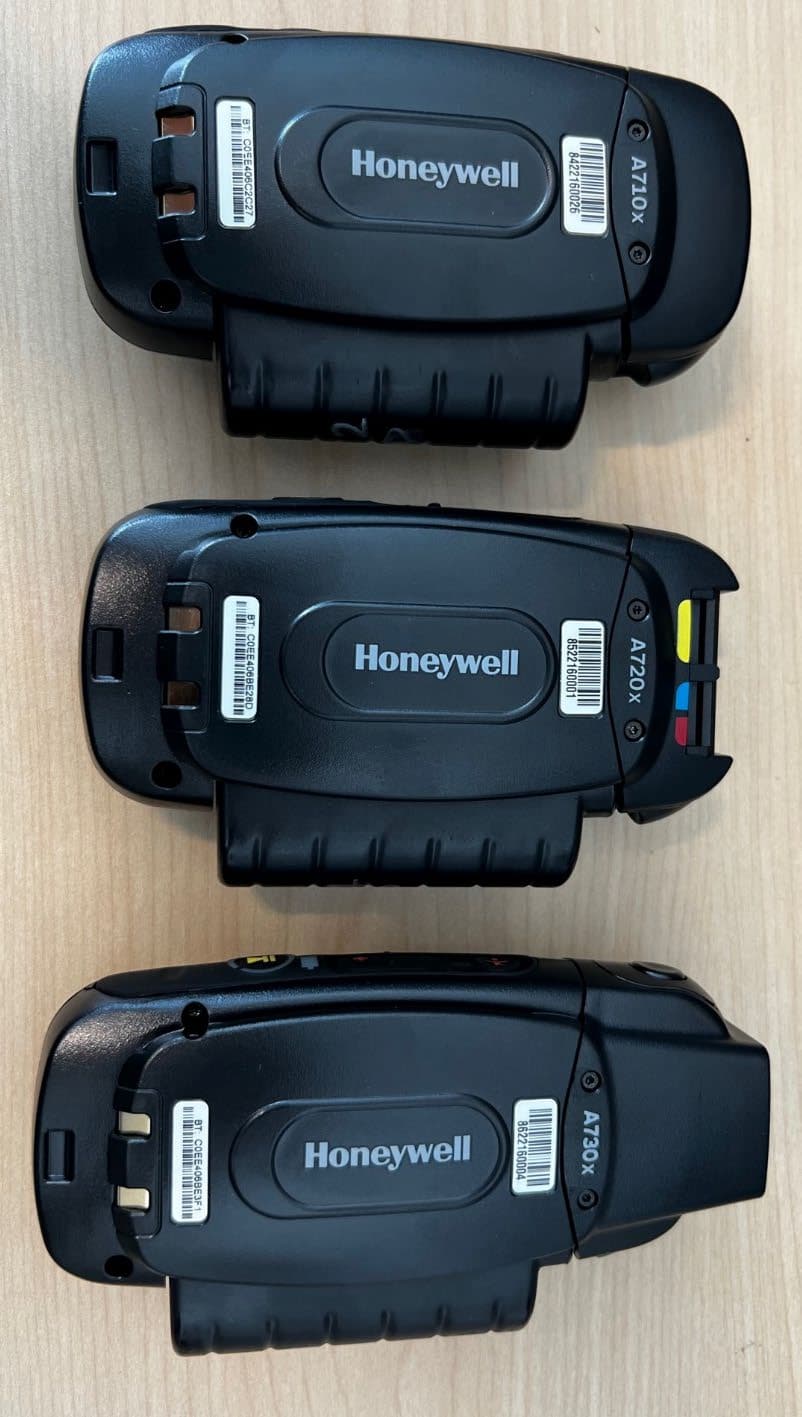
Click to zoom
Application Details
- Equipment Class
- DSS - Part 15 Spread Spectrum Transmitter
- Date of Grant
- Sep 26, 2022
- Application Purpose
- Original Equipment
- Date of Application
- Sep 22, 2022
- Equipment Note
- Handheld Communication Device
- Frequency Range
- 2402.00000000 - 2480.00000000
- Company
- Honeywell International Inc
- Country
- United States
Documents & Files
Document Text
Text extracted from the exhibit documents filed with the FCC. Open a document above to read the original.
Users Manual
Voice Device and Headset Hardware Reference Guide Disclaimer WARNING Honeywell International Inc. (“HII”) reserves the right to make changes in specifications and other information contained in this document without prior notice, and the reader should in all cases consult HII to determine whether any such changes have been made. HII makes no representation or warranties regarding the information provided in this publication. CAUTION HII shall not be liable for technical or editorial errors or omissions contained herein; nor for incidental or consequential damages resulting from the furnishing, performance, or use of this material. This document contains proprietary information that is protected by copyright. All rights are reserved. No part of this document may be photocopied, reproduced, or translated into another language without the prior written consent of HII. ©2022 Honeywell International Inc. All rights reserved. Other product names or marks mentioned in this document may be trademarks or registered trademarks of other companies and are the property of their respective owners. Web Address:www.honeywellaidc.com Other product names or marks mentioned in this document may be trademarks or registered trademarks of other companies and are the property of their respective owners. Patents For patent information, please refer towww.hsmpats.com. Voice Device and Headset Hardware Reference Guideii TABLE OF CONTENTS Chapter 1 - A700/A700x Voice-Enabled Devices1 Device Features1 Introduction2 A700 and A700x LED indicators 4 Device State Indicator 4 Battery Charging Indicator6 Battery Health Indicator7 Near Field Communication (NFC) Indicator7 Bluetooth Indicator8 Network Indicator9 TouchConfig: Bringing Additional A700/A700x Devices Online 9 A700/A700x Battery11 Charging an A700/A700x Battery in a Device 11 Charging an A700/A700x Battery in a Charger12 Inserting a Battery into a Talkman A700/A700x Device13 Removing a Battery from a Talkman A700/A700x Device14 Battery Warm-Up Time15 Installing the USB Driver on Windows15 Collecting Platform Debug Logs from A700 Devices16 Using the A700/A700x16 Turning On an A700/A700x16 Turning Off an A700/A700x 17 Powering Off by Using the Play/Pause Button17 iiiVoice Device and Headset Hardware Reference Guide Precautions17 Loading an Operator's Templates on A700/A700x17 Adjusting the Voice on A700/A700x19 Adjusting the Pitch on A700/A700x20 Adjusting the Volume Using Voice on A700/A700x21 Adjusting the Volume Using Device Buttons on A700/A700x21 Adjusting the Speed on A700/A700x22 Changing the Speaker's Gender on A700/A700x23 Options for Hearing Impaired Users25 Cleaning Procedures for Honeywell Equipment 25 Cleaning Plastics 26 Cleaning Hard Plastics 26 Cleaning Foam and Pliable Plastics26 Cleaning Contacts 26 Understanding Talkman Commands27 Template Training Options27 Training with the Talkman Device Only 28 Visual Training Devices29 Training through VoiceConsole's Display29 Training Using a Printed List of Words29 Scanning with the Talkman A730/A730x Device 30 A730 / A730x Scanner Configuration 31 Symbology Specific31 Postnet31 Planet32 British Post Office (BPO)33 Canada Post33 Australian Post 34 Japan Post35 Sweden Post36 Voice Device and Headset Hardware Reference Guideiv Infomail37 Intelligent Mail37 Codabar38 Code 9339 Code 3940 Code 12842 Interleaved 2 of 544 Matrix 2 of 545 MSI Code46 Plessey Code47 Standard 2 of 5 48 Telepen49 Code 1150 EAN / UPC51 PDF41753 Codablock55 TLC 3955 GS1 DataBar56 Maxicode57 Aztec58 Datamatrix59 QR Code59 GS1 Composite60 IATA 2 of 561 Tri-Optic62 Code 3263 China Post63 Korea Post64 USPS 4-State 65 Coupon Code66 vVoice Device and Headset Hardware Reference Guide ID Tag66 Han Xin Code67 Imager Generic68 Message Format68 Decoding Security68 Imager69 Data Manipulation70 Multicode70 Data Editing74 Talkman A700/A700x VMT Installation Guide 77 Review A700/A700x VMT Installation Best Practices77 Protect Talkman devices from damage78 Consider additional options from RAM® Mounts78 Lock parts into place if they might be moved during normal operations79 Secure VMT cabling79 Select A700/A700x VMT Mounting Option79 Screw-on Mount80 Clamp Mount80 Claw Mount81 Install Vehicle Dock 82 Talkman VMT Parts and Accessories 84 Vehicle-Powered Vehicle Mount Configurations84 Battery-Powered Vehicle Mount Configurations86 Positioning the Talkman A700/A700x Vehicle Dock87 Position the Talkman A700/A700x VMT87 Install the Mounting Brackets88 Mounting Brackets for a Talkman A700/A700x Vehicle Dock88 Route the Electrical Cables90 Precautions 91 Assemble the Vehicle Battery Cable91 Voice Device and Headset Hardware Reference Guidevi Connect to the Top Battery Terminal92 Connect to the Side Battery Terminal92 Fasten the Ground Wire93 Attach the A700/A700x VMT to the Vehicle94 Remove the A700/A700x VMT from the Vehicle94 Chapter 2 - Wireless Headsets 95 Choosing the Right Headset 95 Honeywell Wireless Headset Features96 Care and Use96 SRX2 and SRX3 Industrial Use Headsets96 Introduction to the SRX2 and SRX3 Headsets97 Headset Functions and LED Patterns for SRX2/SRX398 Headset Function 98 Power on98 User Action98 Headset Mode98 LED Pattern98 Tone98 Power off99 User Action99 Headset Mode99 LED Pattern99 Tone99 Increase volume99 User Action99 Headset Mode100 LED Pattern100 Tone 100 Decrease volume100 viiVoice Device and Headset Hardware Reference Guide User Action100 Headset Mode100 LED Pattern100 Tone100 Mute101 User Action101 Headset Mode101 LED Pattern101 Tone101 Unmute101 User Action 101 Headset Mode102 LED Pattern102 Tone102 Force disconnect for manual pairing in low power mode102 User Action102 Headset Mode102 LED Pattern102 Tone103 Switch to high power pairing when pairing in low power mode has failed103 User Action103 Headset Mode103 LED Pattern103 Tone103 Normal operation, paired and connected104 User Action104 Headset Mode104 LED Pattern104 Tone 104 Paired but connection dropped, possibly out of range104 Voice Device and Headset Hardware Refere…
Text truncated - open the document above for the full version.
Cover Letter(s)
Safety and Productivity Solutions 9680 Old Bailes Road Fort Mill, SC 29707 USA www.honeywell.com sps.honeywell.com 050222-17 Authority to Act as Agent Date: August 24, 2022 American Certification Body, Inc. 313 Park Avenue Suite 300 Falls Church, VA 22046 To Whom It May Concern: Ryan Urness and Amanda Hauck of Laird Connectivity, LLC are authorized to act on our behalf, until otherwise notified, for applications to American Certification Body, Inc. (ACB). We certify that we are not subject to denial of federal benefits, that includes FCC benefits, pursuant to Section 5301 of the Anti-Drug Abuse Act of 1988, 21 U.S.C. 862. Further, no party, as defined in 47 CFR 1.2002 (b), to the application is subject to denial of federal benefits, that includes FCC benefits. We also declare that the information provided to the FCC is true and correct to the best of our knowledge (47 CFR 2.911(d)) and we have been informed of the grantee responsibilities (47 CFR 2.909) with regard to certified equipment. Thank you, Agency Agreement Expiration Date: 2022-10-30 By: __________________________ Gretchen Bullen (Signature 1 ) (Print name) Title: Product Compliance, Quality Engineer III On behalf of: Honeywell International Inc. (Company Name) Telephone: (412) 222-4097 1 - Must be signed by applicant contact given for applicant on the FCC site, or by the authorized agent if an appropriate authorized agent letter has been provided. Letters should be placed on appropriate letterhead.
Cover Letter(s)
Safety and Productivity Solutions 9680 Old Bailes Road Fort Mill, SC 29707 USA www.honeywell.com sps.honeywell.com 050222-17 Request for Confidentiality Date: May 25, 2022 Subject: Confidentiality Request for: FCC ID: HD5-TAP1000-02 / IC ID: 1693B-TAP100002 Pursuant to FCC 47 CFR 0.457(d) and 0.459 and/or IC RSP-100, Section 12.4, the applicant requests that a part of the subject application(s) be held confidential. Type of Confidentiality Requested Exhibit ☐ Short Term ☒ Permanent Block Diagrams ☒ Short Term --------------------------- External Photos ☒ Short Term ☐ Permanent * 1 Internal Photos ☐ Short Term ☒ Permanent Operation Description/Theory of Operation ☐ Short Term ☒ Permanent Schematics ☒ Short Term --------------------------- Test Setup Photos ☒ Short Term ☐ Permanent * 1 User’s Manual Honeywell International Inc., has spent substantial effort in developing this product and it is one of the first of its kind in industry. Having the subject information easily available to "competition" would negate the advantage they have achieved by developing this product. Not protecting the details of the design will result in financial hardship. Permanent Confidentiality: The applicant requests the exhibits listed above as permanently confidential be permanently withheld from public review due to materials that contain trade secrets and proprietary information not customarily released to the public. Short-Term Confidentiality for FCC Applications: The applicant requests the exhibits selected above as short term confidential be withheld from public view for a period of 180 days from the date of the Grant of Equipment Authorization and prior to marketing. This is to avoid premature release of sensitive information prior to marketing or release of the product to the public. Applicant is also aware that they are responsible to notify ACB in the event information regarding the product or the product is made available to the public before the requested period has expired. ACB will then release the documents listed above for public disclosure pursuant to FCC Public Notice DA 04-1705. Short Term Confidentiality for Industry Canada Applications: Starting May 2022, ISED will recognize short term confidentiality on certain exhibits until the intended date of marketing. The applicant requests the exhibits selected above as short term confidential be withheld from public view for a period of 180 days from the date of the Equipment Authorization and prior to marketing. Sincerely, By: __________________________ ________________________ (Signature/Title 2 ) Gretchen Bullen Product Compliance, Quality Engineer III 1 - The asterisked items (*) require further information to be provided to ACB before permanent confidentiality will be extended to these exhibits. Please refer to FCC KDB 726920 and the specific Document link for D01 found at: https://apps.fcc.gov/oetcf/kdb/forms/FTSSearchResultPage.cfm?switch=P&id=41731 and review section II, 3) regarding specific information that must accompany these requests. 2 - Must be signed by applicant contact given for applicant on the FCC site, or by the authorized agent if an appropriate authorized agent letter has been provided. Letters should be placed on appropriate letterhead.
Cover Letter(s)
Safety and Productivity Solutions 9680 Old Bailes Road Fort Mill, SC 29707 USA www.honeywell.com www.honeywellaidc.com Date: 03-31-2022 To Whom It May Concern: I am the grantee contact of record for the following FCC grantee codes (codes) held by Honeywell International, Inc. (“Honeywell”): KDZ HD5 RA4 LW5 I hereby authorize, William Jones, Jesautheen Barakath Ali, Cesar Carreon, Gretchen Bullen, while employees of Honeywell, to act on my behalf for any activities related to the above FCC grantee codes, including, but not limited to, signing applications, requesting confidentiality and authorizing third parties to act as authorized agents with respect to the above codes. Honeywell International, Inc. certifies that no party, as defined in 47 CFR §1.2002 (b), to the application is subject to a denial of federal benefits that includes FCC benefits pursuant to Section 5301 of the Anti-Drug Abuse Act of 1988, 21 U.S.C. § 862. This authorization is valid through March 31, 2023, unless withdrawn earlier. Sincerely, Mandana Salahshour [email protected] Regulatory Compliance Manager Honeywell International Inc Safety and Productivity Solutions 9680 Old Bailes Road Fort Mill, SC 29707 Office: +1 803-835-8190
External Photos
Equipment: A700X Series Devices Models: TAP1010-02, TAP1020-02, TAP1030-02 FCC ID: HD5-TAP1000-02 IC ID: 1693B-TAP100002 1 | Page A700X Series Devices External Photos Equipment: A700X Series Devices Models: TAP1010-02, TAP1020-02, TAP1030-02 FCC ID: HD5-TAP1000-02 IC ID: 1693B-TAP100002 2 | Page A710X Keypad and Battery view A710X Product Label without Battery view Equipment: A700X Series Devices Models: TAP1010-02, TAP1020-02, TAP1030-02 FCC ID: HD5-TAP1000-02 IC ID: 1693B-TAP100002 3 | Page A710X Standard Endcap and Battery Latch End view Equipment: A700X Series Devices Models: TAP1010-02, TAP1020-02, TAP1030-02 FCC ID: HD5-TAP1000-02 IC ID: 1693B-TAP100002 4 | Page A720X Keypad and Battery view A720X Product Label without Battery view Equipment: A700X Series Devices Models: TAP1010-02, TAP1020-02, TAP1030-02 FCC ID: HD5-TAP1000-02 IC ID: 1693B-TAP100002 5 | Page A720X 2-TCO Endcap and Battery Latch End view Equipment: A700X Series Devices Models: TAP1010-02, TAP1020-02, TAP1030-02 FCC ID: HD5-TAP1000-02 IC ID: 1693B-TAP100002 6 | Page A730X Keypad and Battery view A730X Product Label without Battery view Equipment: A700X Series Devices Models: TAP1010-02, TAP1020-02, TAP1030-02 FCC ID: HD5-TAP1000-02 IC ID: 1693B-TAP100002 7 | Page A730X Scanner Endcap and Battery Latch End view
ID Label/Location Info
Media Material + UL Rating = UL 969
Internal Photos
Equipment: A700x Series Devices Models: TAP1010-02, TAP1020-02, TAP1030-02 FCC ID: HD5-TAP1000-02 IC ID: 1693B-TAP100002 1 | Page A700x Series Devices Internal Photos A710x Device (Standard Endcap) A710x Disassembled A710x Endcap Equipment: A700x Series Devices Models: TAP1010-02, TAP1020-02, TAP1030-02 FCC ID: HD5-TAP1000-02 IC ID: 1693B-TAP100002 2 | Page A720x Device (2-TCO Endcap) A720x Disassembled Equipment: A700x Series Devices Models: TAP1010-02, TAP1020-02, TAP1030-02 FCC ID: HD5-TAP1000-02 IC ID: 1693B-TAP100002 3 | Page A720x Endcap Equipment: A700x Series Devices Models: TAP1010-02, TAP1020-02, TAP1030-02 FCC ID: HD5-TAP1000-02 IC ID: 1693B-TAP100002 4 | Page A730x Device (Scanner Endcap) A730x disassembled Equipment: A700x Series Devices Models: TAP1010-02, TAP1020-02, TAP1030-02 FCC ID: HD5-TAP1000-02 IC ID: 1693B-TAP100002 5 | Page A730x Endcap Scanner Endcap PCB w/out scanner attached Scanner Endcap PCB w/scanner attached Equipment: A700x Series Devices Models: TAP1010-02, TAP1020-02, TAP1030-02 FCC ID: HD5-TAP1000-02 IC ID: 1693B-TAP100002 6 | Page Main Board PCB w/Shield PCB w/Shield Removed Equipment: A700x Series Devices Models: TAP1010-02, TAP1020-02, TAP1030-02 FCC ID: HD5-TAP1000-02 IC ID: 1693B-TAP100002 7 | Page Radio Board Equipment: A700x Series Devices Models: TAP1010-02, TAP1020-02, TAP1030-02 FCC ID: HD5-TAP1000-02 IC ID: 1693B-TAP100002 8 | Page WLAN 802.11 ac Antenna RFID (13.56MHz) Antenna Connector ( J1 of P/N 1002403 ) RFID (13.56MHz) Radio 802.11 a/b/g/n/ac WLAN plus Bluetooth 5.1 w/Shield Removed Bluetooth Antenna Equipment: A700x Series Devices Models: TAP1010-02, TAP1020-02, TAP1030-02 FCC ID: HD5-TAP1000-02 IC ID: 1693B-TAP100002 9 | Page RFID (13.56MHz) Antenna (P/N 1002403) WLAN 802.11 ac Antenna Equipment: A700x Series Devices Models: TAP1010-02, TAP1020-02, TAP1030-02 FCC ID: HD5-TAP1000-02 IC ID: 1693B-TAP100002 10 | Page WLAN (802.11 ac) Antenna Equipment: A700x Series Devices Models: TAP1010-02, TAP1020-02, TAP1030-02 FCC ID: HD5-TAP1000-02 IC ID: 1693B-TAP100002 11 | Page RFID (13.56MHz) Antenna
RF Exposure Info
© 2022 RF Exposure Lab, LLC This report shall not be reproduced except in full without the written approval of RF Exposure Lab, LLC. 802 N. Twin Oaks Valley Road, Suite 105 • San Marcos, CA 92069 • U.S.A. TEL (760) 471-2100 • FAX (760) 471-2121 http://www.rfexposurelab.com CERTIFICATE OF COMPLIANCE SAR EVALUATION Vocollect, Inc. Dates of Test: May 23-26, 2022 703 Rodi Road Test Report Number: SAR.20220607 Pittsburgh, PA 15235 Revision A This wireless mobile and/or portable device has been shown to be compliant for loca lized specific absorption rate (SAR) for uncontrolled environment/general exposure limits specified in ANSI/IEEE Std. C95.1-1992 and had been tested in accordance with the measurement procedures specified in IEEE 1528-2013 and IEC 62209-1528:2020 (See test report). I attest to the accuracy of the data. All measurements were performed by myself or were made under my supervision and are correct to the best of my knowledge and belief. I assume full responsibility for the completeness of these measurements an d vouch for the qualifications of all persons taking them. RF Exposure Lab, LLC certifies that no party to this application is subject to a denial of Federal benefits that includes FCC benefits pursuant to Section 5301 of the Anti-Drug Abuse Act of 1988, 21 U.S.C. 853(a). Jay M. Moulton Vice President Testing Cert. # 2387.01 FCC ID: HD5-TAP1000-02 IC Certificate: 1693B-TAP100002 HVIN/Model(s): A700x Series Family TAP10x0-02 Contains WLAN Module: Laird Connectivity, LLC Model 60SIPT FCC: SQG-60SIPT IC: 3147A-60SIPT Test Sample: Engineering Unit Same as Production Serial Number: 7418200044, 7518200141, 7618230017 Equipment Type: Handheld Reader containing Wireless Module Classification: Portable Transmitter Next to Body TX Frequency Range: 2412 – 2462 MHz; 5180 – 5320 MHz; 5500 – 5700 MHz; 5745 – 5825 MHz Frequency Tolerance: ± 2.5 ppm Maximum RF Output: 2450 MHz (b) – 18.0 dBm, 2450 MHz (g) – 18.0 dBm, 2450 MHz (n20) – 18.0 dBm, 2450 MHz (n40) – 16.0 dBm, 5250 MHz (a) – 18.0 dBm, 5250 MHz (n/ac20) – 18.0 dBm, 5250 MHz (n/ac40) – 16.0 dBm, 5250 MHz (ac80) – 14.0 dBm, 5600 MHz (a) – 18.0 dBm, 5600 MHz (n/ ac20) – 18.0 dBm, 5600 MHz (n/ac40) – 16.0 dBm, 5600 MHz (ac80) – 14.0 dBm, 5800 MHz (a) – 18.0 dBm, 5800 MHz (n/ac20) – 18.0 dBm, 5800 MHz (n/ac40) – 16.0 dBm, 5800 MHz (ac80) – 14.0 dBm Conducted Signal Modulation: DSSS, OFDM Antenna Type: Internal Application Type: Certification FCC Rule Parts: Part 2, 15C, 15E KDB Test Methodology: KDB 447498 D01 v07, KDB 248227 v02r02, KDB 616217 D04 v01r02 Industry Canada: RSS-102 Issue 5, Safety Code 6 Maximum SAR Value Body: 1.12 W/kg Reported Simultaneous SAR Body: 1.24 W/kg Reported Maximum SAR Value Extremity: 2.16 W/kg Reported Simultaneous SAR Extremity: 2.29 W/kg Reported S eparation Distance: 0 mm Report Number: SAR.20220607 © 2022 RF Exposure Lab, LLC Page 2 of 119 This report shall not be reproduced except in full without the written approval of RF Exposure Lab, LLC. Table of Contents 1. Introduction ........................................................................................................................ 4 SAR Definition [5] ................................................................................................................... 5 2. SAR Measurement Setup ................................................................................................... 6 Robotic System ...................................................................................................................... 6 System Hardware ................................................................................................................... 6 System Electronics ................................................................................................................. 7 Probe Measurement System .................................................................................................. 7 3. Probe and Dipole Calibration .............................................................................................15 4. Phantom & Simulating Tissue Specifications .....................................................................16 Head & Body Simulating Mixture Characterization ................................................................16 5. ANSI/IEEE C95.1 – 1992 RF Exposure Limits [2] ..............................................................17 Uncontrolled Environment .....................................................................................................17 Controlled Environment .........................................................................................................17 6. Measurement Uncertainty .................................................................................................18 7. System Validation..............................................................................................................19 Tissue Verification .................................................................................................................19 Test System Verification ........................................................................................................19 8. SAR Test Data Summary ..................................................................................................21 Procedures Used To Establish Test Signal ...........................................................................21 Device Test Condition ...........................................................................................................21 SAR Data Summary – 2450 MHz Body 802.11b Body ..........................................................47 SAR Data Summary – 2450 MHz Body 802.11b Extremity ...................................................48 SAR Data Summary – 5250 MHz Body 802.11a Body ..........................................................49 SAR Data Summary – 5250 MHz Body 802.11a Extremity ...................................................50…
Text truncated - open the document above for the full version.
Test Report
A Company: Honeywell International Inc. Page 1 of 46 Name: A700x Series Devices (A710x, A720x, A730x) Report: TR3584 E Model: TAP1010-02, TAP1020-02, TAP1030-02 Quote: NBO-01-2022-004630 Serial: Engineering Sample Test Report # 3584 E (BT FHSS) Equipment Under Test: A700x Series Devices (A710x, A720x, A730x) Requirement(s): FCC 15.247, RSS-247 Test Date(s): June 15 th -21 st , 2022 Prepared for: Honeywell International Inc. Attn: Gretchen Bullen 9680 Old Bailes Road Fort Mill, SC 29707 Report Issued by: Adam Alger, Laboratory Manager Signature: Date: 9/15/2022 Report Reviewed by: Adam Alger, Laboratory Manager Signature: Date: 7/6/2022 Report Constructed by: Zach Wilson, EMC Engineer Signature: Date: 7/5/2022 This test report may not be reproduced, except in full, without approval of Laird Connectivity LLC. Company: Honeywell International Inc. Page 2 of 46 Name: A700x Series Devices (A710x, A720x, A730x) Report: TR3584 E Model: TAP1010-02, TAP1020-02, TAP1030-02 Quote: NBO-01-2022-004630 Serial: Engineering Sample CONTENTS Laird Connectivity Test Services in Review ............................................................................................... 3 1 Test Report Summary ........................................................................................................................... 4 2 Client Information ................................................................................................................................. 5 2.1 Equipment Under Test (EUT) Information .................................................................................... 5 2.2 Product Description ...................................................................................................................... 5 2.3 Modifications Incorporated for Compliance ................................................................................. 5 2.4 Deviations and Exclusions from Test Specifications ..................................................................... 6 2.5 Channels and Data Rates .............................................................................................................. 6 2.6 Radio Programming ...................................................................................................................... 6 2.7 Antenna ......................................................................................................................................... 6 2.8 Simultaneous Transmission .......................................................................................................... 6 3 References ............................................................................................................................................ 7 4 Uncertainty Summary ........................................................................................................................... 8 5 Test Data ............................................................................................................................................... 9 5.1 Antenna Port Conducted Emissions .............................................................................................. 9 5.1.1 Bandwidth ........................................................................................................................... 10 5.1.2 Output Power ...................................................................................................................... 17 5.1.3 Conducted Spurious Emissions ........................................................................................... 21 5.1.4 Frequency Stability .............................................................................................................. 28 5.1.5 FHSS ..................................................................................................................................... 29 5.2 Radiated Emissions ..................................................................................................................... 33 5.2.1 Radiated Emissions ............................................................................................................. 34 6 Revision History .................................................................................................................................. 46 Company: Honeywell International Inc. Page 3 of 46 Name: A700x Series Devices (A710x, A720x, A730x) Report: TR3584 E Model: TAP1010-02, TAP1020-02, TAP1030-02 Quote: NBO-01-2022-004630 Serial: Engineering Sample Laird Connectivity Test Services in Review The Laird Connectivity, Inc. laboratory located at W66 N220 Commerce Court Cedarburg, Wisconsin, 53012 USA is recognized through the following organizations: A2LA – American Association for Laboratory Accreditation Accreditation based on ISO/IEC 17025:2017 with Electrical (EMC) Scope A2LA Certificate Number: 1255.01 Scope of accreditation includes all test methods listed herein unless otherwise noted Federal Communications Commission (FCC) – USA Accredited Test Firm Registration Number: 953492 Recognition of two 3 meter Semi-Anechoic Chambers Innovation, Science and Economic Development Canada Accredited U.S. Identification Number: US0218 Recognition of two 3 meter Semi-Anechoic Chambers Company: Honeywell International Inc. Page 4 of 46 Name: A700x Series Devices (A710x, A720x, A730x) Report: TR3584 E Model: TAP1010-02, TAP1020-02, TAP1030-02 Quote: NBO-01-2022-004630 Serial: Engineering Sample 1 TEST REPORT SUMMARY During June 15 th -21 st , 2022 the Equipment Under Test (EUT), A700x Series Devices (A710x, 720x, 730x), as provided by Honeywell International Inc. was tested to the following requirements Federal Communications Commission and Innovation, Science and Economic Development Canada: FCC 15.247 / RSS-247, FHSS Requirement Description Specification Method Result FCC: 15.247 (a)(1) IC: RSS-247 5.1 Channel Separation, Number of Hopping frequencies, Time of Occupancy FHSS ANSI C63.10 Compliant …
Text truncated - open the document above for the full version.
Test Report
A Company: Honeywell International Inc. Page 1 of 16 Name: A700x Series Devices (A710x, A720x, A730x) Report: TR3584 G Model: TAP1010-02, TAP1020-02, TAP1030-02 Quote: NBO-01-2022-004630 Serial: Engineering Sample Test Report # 3584 G (Simultaneous Transmit) Equipment Under Test: A700x Series Devices (A710x, A720x, A730x) Requirement(s): FCC 15.247 / 15.209, RSS-247 / RSS-GEN Test Date(s): May 31 st – June 2 nd , 2022 Prepared for: Honeywell International Inc. Attn: Gretchen Bullen 9680 Old Bailes Road Fort Mill, SC 29707 Report Issued by: Adam Alger, Laboratory Manager Signature: Date: 9/15/2022 Report Reviewed by: Adam Alger, Laboratory Manager Signature: Date: 7/6/2022 Report Constructed by: Zach Wilson, EMC Engineer Signature: Date: 7/5/2022 This test report may not be reproduced, except in full, without approval of Laird Connectivity LLC. Company: Honeywell International Inc. Page 2 of 16 Name: A700x Series Devices (A710x, A720x, A730x) Report: TR3584 G Model: TAP1010-02, TAP1020-02, TAP1030-02 Quote: NBO-01-2022-004630 Serial: Engineering Sample CONTENTS Laird Connectivity Test Services in Review ............................................................................................... 3 1 Test Report Summary ........................................................................................................................... 4 2 Client Information ................................................................................................................................. 5 2.1 Equipment Under Test (EUT) Information .................................................................................... 5 2.2 Product Description ...................................................................................................................... 5 2.3 Modifications Incorporated for Compliance ................................................................................. 5 2.4 Deviations and Exclusions from Test Specifications ..................................................................... 6 2.5 Simultaneous Transmission .......................................................................................................... 6 3 References ............................................................................................................................................ 7 4 Uncertainty Summary ........................................................................................................................... 8 5 Test Data ........................................................................................................…
Text truncated - open the document above for the full version.
Contact Information
Applicant
Cindy Jiang(Global Regulatory Compliance Manager)
Technical Contact
Honeywell International IncGretchen National Technical Systems-Silicon Valley Bullen
2555 Smallman Street · Pittsburgh · United States
Test Firm
EzurioAdam Alger
Technical Specifications
| # | Rule Parts | Frequency Range | Power Output |
|---|---|---|---|
| 1 | 15C | 2.40 GHz - 2.48 GHz | 10.20 mW |
Other Applications from Honeywell International Inc
HD5-CT47HFUHF
Aug 04, 2026A rugged accessory for the Honeywell CT47 mobile computer which enables HF and UHF reading. Reader is supplied from mobile computer CT47.
Equipment Class
DXX - Part 15 Low Power Communication Device TransmitterHD5CT47HFUHF
Aug 04, 2026A rugged accessory for the Honeywell CT47 mobile computer which enables HF and UHF reading. Reader is supplied from mobile computer CT47.
Equipment Class
DTS - Digital Transmission SystemHD5-8680IC
Jun 17, 2026Barcode Scanner
Equipment Class
DSS - Part 15 Spread Spectrum TransmitterHD5-CT70X1
Jan 26, 2026Mobile Computer
Equipment Class
CBE - Citizens Band End User DevicesHD5-1972
Dec 25, 2025Barcode Scanner
Equipment Class
DSS - Part 15 Spread Spectrum Transmitter