HD57900BU0EHandheld PC with GSM
Honeywell International Inc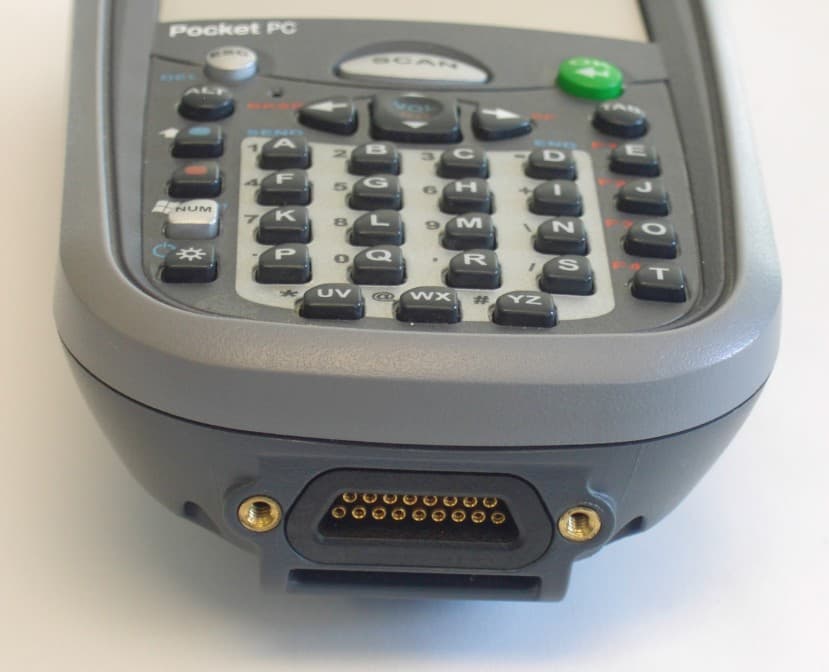
Click to zoom
Application Details
- Equipment Class
- PCE - PCS Licensed Transmitter held to ear
- Date of Grant
- Sep 25, 2006
- Application Purpose
- Original Equipment
- Date of Application
- Sep 25, 2006
- Equipment Note
- Handheld PC with GSM
- Frequency Range
- 824.20000000 - 848.80000000
- Company
- Honeywell International Inc
- Country
- United States
Documents & Files
Document Text
Text extracted from the exhibit documents filed with the FCC. Open a document above to read the original.
Users Manual
User’s Guide– Preliminary Dolphin ® 7900 Series Microsoft ® Windows Mobile ® 5.0 Disclaimer Hand Held Products, Inc. (“Hand Held Products”) reserves the right to make changes in specifications and other information contained in this document without prior notice, and the reader should in all cases consult Hand Held Products to determine whether any such changes have been made. The information in this publication does not represent a commitment on the part of Hand Held Products. Hand Held Products shall not be liable for technical or editorial errors or omissions contained herein; nor for incidental or consequential damages resulting from the furnishing, performance, or use of this material. This document contains proprietary information that is protected by copyright. All rights are reserved. No part of this document may be photocopied, reproduced, or translated into another language without the prior written consent of Hand Held Products. © 2006 Hand Held Products, Inc. All rights reserved. Web Address: www.handheld.com Trademarks Dolphin, HomeBase, Mobile Base, and QuadCharger are trademarks or registered trademarks of Hand Held Products, Inc. Windows Mobile, Windows, Windows NT, Windows 2000, Windows ME, Windows XP, ActiveSync, Outlook, and the Windows logo are trademarks or registered trademarks of Microsoft Corporation. Intel is a registered trademark of Intel Corporation. Chapter 9 (pages 9-1–9-11) contains copyrighted information from SyChip, Inc. Chapter 9 (pages 9-12–9-39) contains copyrighted information from Meetinghouse Corporation. Meetinghouse, the Meetinghouse logo, and all other Meetinghouse trademarks/service marks contained herein are trademarks or registered trademarks of Meetinghouse. Chapter 10 is copyrighted information used by permission from Bluetooth SIG, Inc. The Bluetooth trademarks are owned by Bluetooth SIG, Inc., U.S.A. and licensed to Hand Held Products. Chapter 11 contains information with permission from Intrynsic Software, Inc. Other product names mentioned in this manual may be trademarks or registered trademarks of their respective companies and are the property of their respective owners. Dolphin® 7900 Series User’s Guide–Preliminaryiii Chapter 1 - Introduction Required Safety Labels ....................................................................................................................... 1-2 Laser Safety Label ........................................................................................................................ 1-2 Regulatory and Safety Approvals for all Dolphin 7900 Series Terminals .........................................1-3 FCC Compliance ................................................................................................................................. 1-6 Chapter 2 - Getting Started Overview ............................................................................................................................................. 2-1 Dolphin 7900 Radio Configuration Options .......................................................................................2-2 Standard Configurations ............................................................................................................... 2-2 Custom Configurations................................................................................................................. 2-2 Dolphin 7900 Series Peripherals ......................................................................................................... 2-3 Dolphin 7900 Accessories................................................................................................................... 2-4 Using the Dolphin 7900 for the First Time ......................................................................................... 2-5 Resetting the Terminal ........................................................................................................................ 2-9 Soft Reset (Warm Boot) ............................................................................................................... 2-9 Hard Reset (Cold Boot) ................................................................................................................ 2-9 Suspend Mode ..................................................................................................................................... 2-9 Chapter 3 - Hardware Overview System Features .................................................................................................................................. 3-1 Front Panel Features............................................................................................................................ 3-2 Back Panel Features ............................................................................................................................ 3-4 Side Panel Features ............................................................................................................................. 3-6 Opening the Access Door ............................................................................................................. 3-6 Replacing the Access Door........................................................................................................... 3-8 Bottom Panel Features ........................................................................................................................ 3-9 Mechanical Connector .................................................................................................................. 3-9 Battery Power.................................................................................................................................... 3-10 Main Battery Pack ...................................................................................................................... 3-10 Internal Backup Battery...........................................................................................................…
Text truncated - open the document above for the full version.
Users Manual
Dolphin® 7900 Series User’s Guide– Preliminary Rev (e)9 - 17 System Tab The System Settings tab controls logging and the port manger timeout period. FieldDescription Log LevelThese settings control the detail of the log messages generated by the Client. Each level is cumula- tive. By default, all errors, warnings, and information events are logged. Each entry records a severity code (of one [debug message] to four [error] asterisks), a time stamp, and a message. •Errors - only the most severe conditions are logged. •Warnings - less severe conditions are logged. •Information - all errors, warnings, and information events are logged. This is the default setting. •Debugging - creates a log message each time the Client detects or reacts to an event. Be advised that log entries fill memory quickly if the Debugging level is chosen. Do not use the Debugging option for a significant length of time because most internal operations generate messages. DefaultsTap this button to return log settings to the default settings. Disable Wireless Zero Config Use this option only as directed by technical support. Selecting this option disables other wireless utilities whether the Client is running or not. If not selected, other wireless utilities cannot apply their settings to the wireless card while the Client is run - ning (although their status displays are usually unaffected). You will need to perform a soft reset whenever this setting is changed. Port Manager Timeout The interval at which the client polls the ports. This is used under different circumstances, for instance after physical changes such as card removal or insertion have been detected. This value should not be changed from the 10-second default unless so advised by technical support. 9 - 18Rev (e)Dolphin® 7900 Series User’s Guide–Preliminary Server Tab The Server identity tab defines the credentials the client uses to authenticate the server during TLS/TTLS/PEAP authentication message exchange. The Client uses this information to verify that the Client is communicating with a trusted server. FieldDescription Do not validate server certificate chain If this option is selected, the server certificate received during the TLS/TTLS/PEAP message exchange is not validated. Certificate issuer must be This is the certificate authority used during TLS/TTLS/PEAP message exchange. Any Trusted CA is the default selection and means that any certificate authority can be used during authen - tication. Both trusted intermediate certificate authorities and root authorities whose certificates exist in the system store are available for selection in the drop-down list. Allow intermediate certificates This option is selected by default and enables unspecified certificates to be in the server certifi- cate chain between the server certificate and the certificate authority selected in the Certificate issuer must be field. When selected, this option allows the server certificate received during negotiation to be issued directly by the certificate authority or by one of its intermediate certificate authorities. If disabled, then the selected Certificate issuer must have directly issued the server certificate. Server name must beThis is either the server name or the domain the server belongs to, depending on which option is selected below the text field. During authentication, this name will be compared to the server certificate’s Subject: CN field. Must match exactlyWhen selected, the server name entered must match the server name found on the certificate exactly. Must contain domain name When selected, the server name field identifies a domain and the certificate must have a server name belonging to this domain or to one of its sub-domains (e.g., zeelans.com, where the server is blueberry.zeelans.com). Configuring the Port On the main screen, tap and hold on a port, and select Configure on the popup menu. The Port Settings Configuration screen opens displaying the Wireless Networks tab. Dolphin® 7900 Series User’s Guide– Preliminary Rev (e)9 - 19 Wireless Networks Tab Field Description Available Networks Displays the networks the terminal recognizes as available to connect to. When the Client is first installed, there are no entries in the Available Networks list. ScanDisplays a list of networks broadcasting their availability. You can also attach to networks who are not broadcasting. Move to ConfiguredActivates after Scan has been tapped and the available networks have been retrieved. In the list of networks retrieved, select the network you wish to connect to, and tap Move to Configured. This selects the network. Configured Networks Displays the networks your terminal is connected to. This section adds and removes networks as well as reviews and edits the properties of existing configured networks. DefaultWhen the Client is first installed, there is a Configured Network named "default" in the list. This profile has Associate with any network selected in its Properties selection screen. If you are going to be in a location with only one AP (or more than one AP that attaches to the same network), the default profile may be sufficient for you needs, without necessitating the selection of a specific network or networks. If default is last in the list, it can act as a wildcard should you be out of the range of your primary networks (which are listed first). Do not place default at the top or middle of the list because, if it is, connection to the other list entries will never be attempted. UpMoves a selected network up one place in the list. DownMoves a selected network down one place in the list. Note: The order of the networks in this list is the exact order that connections will be attempted. The network listed first will be attempted first and so on. Place your primary networks first. AddManually adds a network to the Configured Networks list if the AP does not broadcast its SSID or you are pre-configuring the client for an AP that is not currently in range. Remo…
Text truncated - open the document above for the full version.
External Photos
Page 1 of 3 7900 Front and Back Views 7900 MC 75 Terminal Photos External FCC-ID : HD57900BU0E IC-ID : 1693B-79E Page 2 of 3 7900 Left and Right Side Views Photos External FCC-ID : HD57900BU0E IC-ID : 1693B-79E Page 3 of 3 7900 Top and Bottom Views Photos External FCC-ID : HD57900BU0E IC-ID : 1693B-79E
ID Label/Location Info
Page 8 of 10 7900 “BU0E” Unit Configuration MC75 GSM Radio Included 7900 “BU0E” Label Placement 7900 “BU0E” Radio Placement Internal
Internal Photos
7900 Front and Back Views 7900 MC 75 Terminal 7900 Left and Right Side Views 7900 Top and Bottom Views 7900 “BU0E” Unit Configuration MC75 GSM Radio Included 7900 “BU0E” Label Placement 7900 “BU0E” Radio Placement Internal Front and Back Views of MC75 GSM Placement of GSM Module MC75 GSM Radio Front and Back Placement of GSM Module in device 7900 Internal Board Views Main Board Front and Back Views Key Board Front and Back Views GSM Power Board Front and Back Views
RF Exposure Info
TTI-P-G 081/94-A0 Accredited according to ISO/IEC 17025 Bluetooth Qualification Test Facility (BQTF) FCC listed# 101450 IC recognized # 3925 CETECOM Inc. 411 Dixon Landing Road Milpitas, CA 95035 U.S.A. Phone: + 1 (408) 586 6200 Fax: + 1 (408) 586 6299 E-mail: [email protected] http://www.cetecom.com CETECOM Inc. is a Delaware Corporation with Corporation number: 2113686 Board of Directors: Dr. Harald Ansorge, Dr. Klaus Matkey, Hans Peter May V.2.16M-2002-03-12 \\stupendousman\rootappsdata\emc\projects_emc\hhp\handh_015_06002_d7900_mc75\2_test_reports\sar\gs m_hd57900bu0e\sar_handh_014_06002_d7900_850_1900.doc © Copyright by CETECOM SAR Test Report No.: SAR_HANDH_015_06002_D7900_MC75_850_1900 for the Handheld Products Handheld Computer Model Number: Dolphin 7900 FCC ID: HD57900BU0E Date of Report: 08/28/2006 Date of issue: 08/28/2006 Report Copy No.: 01 SAR Test Report No. SAR_HANDH_015_06002_D7900_MC75_850_1900 Date of Report: 08/28/2006 Page 2 of 33 This report shall not be reproduced except in full without the written approval of: CETECOM Inc. SAR 411 Dixon Landing Road Milpitas, CA 95035 U.S.A. Contents 1 ASSESSMENT ...................................................................................................................4 2 ADMINISTRATIVE DATA...................................................................................................4 2.1 Identification of the Testing Laboratory Issuing the SAR Assessment Report ...............5 2.2 Identification of the Client...........................................................................................5 2.3 Identification of the Manufacturer...............................................................................5 3 EQUIPMENT UNDER INVESTIGATION (EUI)...................................................................6 3.1 Identification of the Equipment under Investigation ...................................................6 4 SUBJECT OF INVESTIGATION ........................................................................................7 4.1 The IEEE Standard C95.1 and the FCC Exposure Criteria .......................................7 4.2 Distinction Between Exposed Population, Duration of Exposure and Frequencies...7 4.3 Distinction between Maximum Permissible Exposure and SAR Limits......................8 4.4 SAR Limit ...................................................................................................................8 5 THE FCC MEASUREMENT PROCEDURE .......................................................................9 5.1 General Requirements...............................................................................................9 5.2 Device Operating Next to a Person’s Ear ................................................................10 5.3 Test positions of device relative to head..................................................................11 5.4 Test to be Performed ...............................................................................................14 5.5 Body-worn and Other Configurations.......................................................................14 5.6 Procedure for assessing the peak spatial-average SAR .........................................15 5.7 Determination of the largest peak spatial-average SAR ..........................................17 6 THE MEASUREMENT SYSTEM ......................................................................................18 6.1 Robot system specification ......................................................................................18 6.2 Probe and amplifier specification .............................................................................19 6.3 Phantoms.................................................................................................................20 6.4 SAR measurement procedure .................................................................................22 6.5 SARA2 Interpolation and Extrapolation schemes ....................................................22 6.6 Interpolation of 2D area scan...................................................................................23 SAR Test Report No. SAR_HANDH_015_06002_D7900_MC75_850_1900 Date of Report: 08/28/2006 Page 3 of 33 This report shall not be reproduced except in full without the written approval of: CETECOM Inc. SAR 411 Dixon Landing Road Milpitas, CA 95035 U.S.A. 6.7 Extrapolation of 3D scan..........................................................................................23 6.8 Interpolation of 3D scan and volume averaging.......................................................23 7 UNCERTAINTY ASSESSMENT.......................................................................................25 7.1 Table of Measurement Uncertainty Values of SAR Evaluations..............................26 7.2 Table of Measurement Uncertainty Values for SAR System Verification ................27 8 TEST RESULTS SUMMARY............................................................................................28 8.1 Output Power ...........................................................................................................28 8.2 Test Positions and Configurations ...........................................................................28 8.3 GPRS Operating mode ............................................................................................29 8.4 Head SAR results for GSM 850MHz band for Dolphin 7900 ...................................30 8.5 Body SAR results for GSM 850MHz band for Dolphin 7900....................................30 8.6 Head SAR results for GSM 1900MHz band for Dolphin 7900 .................................30 8.7 Body SAR results for GSM 1900MHz band for Dolphin 7900..................................30 8.8 Validation Check Results .........................................................................................31 9 REFERENCES.....................................…
Text truncated - open the document above for the full version.
RF Exposure Info
SAR Test Report No.: SAR_HANDH_015_06002_D7900_MC75_850_1900 Date of Report: 8/28/2006 Appendix A Plots Page 1 of 18 System / software: SARA2 / 2.40 VPM Input Power Drift: Date / Time: 8/8/2006 9:07:01 AM DUT Battery Model/No: Filename: temp.txt Probe Serial Number: M0016 Ambient Temperature: 22.8°C Liquid Simulant: 850 Device Under Test: HHP D7900 MC75 Relative Permittivity: 41.09 Relative Humidity: 30% Conductivity: 0.917 Phantom S/No: Head04_37.csv Liquid Temperature: 22.0°C Phantom Rotation: 0° Max SAR Y-axis Location: -9.00 mm DUT Position: left touch Max SAR Z-axis Location: -104.80 mm Antenna Configuration: integral Max E Field: 17.13 V/m Test Frequency: 836.6MHz SAR 1g: 0.257 W/kg Air Factors: 2390 / 2143 / 2668 SAR 10g: 0.184 W/kg Conversion Factors: .273 / .273 / .273 SAR Start: 0.158 W/kg Type of Modulation: SAR End: 0.155 W/kg Modn. Duty Cycle: SAR Drift during Scan: -1.90 % Diode Compression Factors (V*200): 20 / 20 / 20 Probe battery last changed: 8/7/06 Input Power Level: max Extrapolation: poly4 SAR Test Report No.: SAR_HANDH_015_06002_D7900_MC75_850_1900 Date of Report: 8/28/2006 Appendix A Plots Page 2 of 18 System / software: SARA2 / 2.40 VPM Input Power Drift: Date / Time: 8/8/2006 9:32:21 AM DUT Battery Model/No: Filename: lefttch190.txt Probe Serial Number: M0016 Ambient Temperature: 22.8°C Liquid Simulant: 850 Device Under Test: HHP D7900 MC75 Relative Permittivity: 41.09 Relative Humidity: 30% Conductivity: 0.917 Phantom S/No: Head04_37.csv Liquid Temperature: 22.0°C Phantom Rotation: 0° Max SAR Y-axis Location: 2.00 mm DUT Position: left tilt Max SAR Z-axis Location: -98.40 mm Antenna Configuration: integral Max E Field: 17.29 V/m Test Frequency: 836.6MHz SAR 1g: 0.249 W/kg Air Factors: 2390 / 2143 / 2668 SAR 10g: 0.180 W/kg Conversion Factors: .273 / .273 / .273 SAR Start: 0.149 W/kg Type of Modulation: SAR End: 0.152 W/kg Modn. Duty Cycle: SAR Drift during Scan: 2.39 % Diode Compression Factors (V*200): 20 / 20 / 20 Probe battery last changed: 8/7/06 Input Power Level: max Extrapolation: poly4 SAR Test Report No.: SAR_HANDH_015_06002_D7900_MC75_850_1900 Date of Report: 8/28/2006 Appendix A Plots Page 3 of 18 System / software: SARA2 / 2.40 VPM Input Power Drift: Date / Time: 8/8/2006 10:10:51 AM DUT Battery Model/No: Filename: lefttlt190.txt Probe Serial Number: M0016 Ambient Temperature: 22.8°C Liquid Simulant: 850 Device Under Test: HHP D7900 MC75 Relative Permittivity: 41.09 Relative Humidity: 30% Conductivity: 0.917 Phantom S/No: Head04_37.csv Liquid Temperature: 22.0°C Phantom Rotation: 180° Max SAR Y-axis Location: 6.00 mm DUT Position: right touch Max SAR Z-axis Location: -135.00 mm Antenna Configuration: integral Max E Field: 14.05 V/m Test Frequency: 836.6MHz SAR 1g: 0.179 W/kg Air Factors: 2390 / 2143 / 2668 SAR 10g: 0.135 W/kg Conversion Factors: .273 / .273 / .273 SAR Start: 0.117 W/kg Type of Modulation: SAR End: 0.113 W/kg Modn. Duty Cycle: SAR Drift during Scan: -2.90 % Diode Compression Factors (V*200): 20 / 20 / 20 Probe battery last changed: 8/7/06 Input Power Level: max Extrapolation: poly4 SAR Test Report No.: SAR_HANDH_015_06002_D7900_MC75_850_1900 Date of Report: 8/28/2006 Appendix A Plots Page 4 of 18 System / software: SARA2 / 2.40 VPM Input Power Drift: Date / Time: 8/8/2006 11:46:53 AM DUT Battery Model/No: Filename: righttch190.txt Probe Serial Number: M0016 Ambient Temperature: 22.8°C Liquid Simulant: 850 Device Under Test: HHP D7900 MC75 Relative Permittivity: 41.09 Relative Humidity: 30% Conductivity: 0.917 Phantom S/No: Head04_37.csv Liquid Temperature: 22.0°C Phantom Rotation: 180° Max SAR Y-axis Location: -7.00 mm DUT Position: right tilt Max SAR Z-axis Location: -130.00 mm Antenna Configuration: integral Max E Field: 13.97 V/m Test Frequency: 836.6MHz SAR 1g: 0.158 W/kg Air Factors: 2390 / 2143 / 2668 SAR 10g: 0.122 W/kg Conversion Factors: .273 / .273 / .273 SAR Start: 0.109 W/kg Type of Modulation: SAR End: 0.107 W/kg Modn. Duty Cycle: SAR Drift during Scan: -1.33 % Diode Compression Factors (V*200): 20 / 20 / 20 Probe battery last changed: 8/7/06 Input Power Level: max Extrapolation: poly4 SAR Test Report No.: SAR_HANDH_015_06002_D7900_MC75_850_1900 Date of Report: 8/28/2006 Appendix A Plots Page 5 of 18 System / software: SARA2 / 2.40 VPM Input Power Drift: Date / Time: 8/8/2006 12:15:37 PM DUT Battery Model/No: Filename: righttlt190.txt Probe Serial Number: M0016 Ambient Temperature: 22.8°C Liquid Simulant: 850 Device Under Test: HHP D7900 MC75 Relative Permittivity: 41.95 Relative Humidity: 30% Conductivity: 0.911 Phantom S/No: Head04_37.csv Liquid Temperature: 22.0°C Phantom Rotation: 0° Max SAR Y-axis Location: -6.00 mm DUT Position: left touch Max SAR Z-axis Location: -104.00 mm Antenna Configuration: integral Max E Field: 17.19 V/m Test Frequency: 824.2MHz SAR 1g: 0.246 W/kg Air Factors: 2390 / 2143 / 2668 SAR 10g: 0.183 W/kg Conversion Factors: .273 / .273 / .273 SAR Start: 0.148 W/kg Type of Modulation: SAR End: 0.156 W/kg Modn. Duty Cycle: SAR Drift during Scan: 4.87 % Diode Compression Factors (V*200): 20 / 20 / 20 Probe battery last changed: 8/7/06 Input Power Level: max Extrapolation: poly4 SAR Test Report No.: SAR_HANDH_015_06002_D7900_MC75_850_1900 Date of Report: 8/28/2006 Appendix A Plots Page 6 of 18 System / software: SARA2 / 2.40 VPM Input Power Drift: Date / Time: 8/8/2006 12:37:44 PM DUT Battery Model/No: Filename: lefttch128.txt Probe Serial Number: M0016 Ambient Temperature: 22.8°C Liquid Simulant: 850 Device Under Test: HHP D7900 MC75 Relative Permittivity: 41.38 Relative Humidity: 30% Conductivity: 0.923 Phantom S/No: Head04_37.csv Liquid Temperature: 22.0°C Phantom Rotation: 0° Max SAR Y-axis Location: -4.00 mm DUT Position: left touch Max SAR Z-axis Location: -103.00 mm Antenna Configuration: integral Max E Field: 17.29 V/m Test Frequency: 848.8MHz SAR 1g: 0.271 W/kg Air Factors: 2390 / 2143 / 2668 SAR 10g: 0.188 W/kg Conversion Factors: .273 / .273 / .273 SAR Start: 0.151 W/kg Type of Modulation:…
Text truncated - open the document above for the full version.
RF Exposure Info
SAR Test Report No.: SAR_HANDH_015_06002_D7900_MC75 _850_1900 Date of Report: 8/28/2006 Appendix B Page 1 of 9 Appendix B: Photos EUT Photos: Photo 1. EUT front SAR Test Report No.: SAR_HANDH_015_06002_D7900_MC75 _850_1900 Date of Report: 8/28/2006 Appendix B Page 2 of 9 Photo 2. EUT back SAR Test Report No.: SAR_HANDH_015_06002_D7900_MC75 _850_1900 Date of Report: 8/28/2006 Appendix B Page 3 of 9 Setup Photos Photo 3. Left touch SAR Test Report No.: SAR_HANDH_015_06002_D7900_MC75 _850_1900 Date of Report: 8/28/2006 Appendix B Page 4 of 9 Photo 4. Left tilt SAR Test Report No.: SAR_HANDH_015_06002_D7900_MC75 _850_1900 Date of Report: 8/28/2006 Appendix B Page 5 of 9 Photo 5. Right touch SAR Test Report No.: SAR_HANDH_015_06002_D7900_MC75 _850_1900 Date of Report: 8/28/2006 Appendix B Page 6 of 9 Photo 6. Right tilt SAR Test Report No.: SAR_HANDH_015_06002_D7900_MC75 _850_1900 Date of Report: 8/28/2006 Appendix B Page 7 of 9 Photo 7 Belt clip touching phantom. SAR Test Report No.: SAR_HANDH_015_06002_D7900_MC75 _850_1900 Date of Report: 8/28/2006 Appendix B Page 8 of 9 Photo 8. Photo to demonstrate 15 cm Z-axis head phantom SAR Test Report No.: SAR_HANDH_015_06002_D7900_MC75 _850_1900 Date of Report: 8/28/2006 Appendix B Page 9 of 9 Photo9: Photo to demonstrate 15 cm Z-axis flat phantom
RF Exposure Info
SAR Test Report No: SAR_ HANDH_015_06002_D7900_MC75 _850_1900 Date of Report:8/28/2006 Appendix C Calibration Info Page 1 of 30 Tissue Parameters 850MHz Head liquid: Recipe: The following recipe is provided in percentage by weight. 49.46% distilled water 49.46% DGBE 1.0% salt 0.1% bactericide SAR measurements were made within 24 hours of the measurement of liquid parameters. Freq. Rel. Condy (MHz) Perm. (S/m) 8/7/06 900 41.55 0.982 8/8/06 824.2 41.95 0.911 8/8/06 836.0 41.09 0.917 8/8/06 848.8 41.38 0.923 850MHz Body Liquid: Recipe: The following recipe is provided in percentage by weight. 49.8% distilled water 40.6% DGBE 8.9% salt 0.6% HEC 0.1% bactericide Di-electric constants measured on 8/7/2006. SAR measurements were made within 24 hours of the measurement of liquid parameters. Freq. Rel. Condy (MHz) Perm. (S/m) 824.2 54.82 0.958 836.0 54.66 0.961 848.8 54.56 0.967 SAR Test Report No: SAR_ HANDH_015_06002_D7900_MC75 _850_1900 Date of Report:8/28/2006 Appendix C Calibration Info Page 2 of 30 1900MHz Head liquid: Recipe: The following recipe is provided in percentage by weight. 54.9% distilled water 44.92% DGBE 0.18% salt 0.1% bactericide SAR measurements were made within 24 hours of the measurement of liquid parameters. Freq. Rel. Condy (MHz) Perm. (S/m) 8/7/06 1900 39.29 1.437 8/8/06 1850.2 39.66 1.403 8/8/06 1880 39.38 1.424 8/8/06 1909.8 39.12 1.45 1900MHz Body Liquid: Recipe: The following recipe is provided in percentage by weight. 69.17% distilled water 30.29% DGBE 0.44% salt 0.1% bactericide Di-electric constants measured on 8/7/06. SAR measurements were made within 24 hours of the measurement of liquid parameters. Freq. Rel. Condy (MHz) Perm. (S/m) 1850.2 52.63 1.515 1880 52.43 1.55 1909.8 52.27 1.564 Environment: Temperature: 22.0 °C ± 2°C Humidity: 45% _ 55 % SAR Test Report No: SAR_ HANDH_015_06002_D7900_MC75 _850_1900 Date of Report:8/28/2006 Appendix C Calibration Info Page 3 of 30 Test Equipment Test Equipment Model Serial Instrument description Supplier / Manufacturer Model Serial No. Calibration (date) Calibration Due (date) Bench top Robot Mitsubishi supplied by IndexSAR RV-E2 EA1030108 N/A N/A SAM Phantom Upright shell phantom made by Antennessa digitized and mounted by IndexSAR SAM 03FT26 04/03 N/A Flat Phantom IndexSAR HeadBox_Spou t N/A N/A N/A Software IndexSAR SARA2 v2.41 VPM N/A N/A N/A 900 MHz Head Tissue Simulant Cetecom Inc. 900 Head N/A 8/7/2006 & 8/8/2006 N/A 850 MHz Body Tissue Simulant Cetecom Inc. 850 Body N/A 8/7/2006 N/A 1900 MHz Head Tissue Simulant Cetecom Inc. 1900 Head N/A 8/7/2006 & 8/8/2006 N/A 1900 MHz Body Tissue Simulant Cetecom Inc. 1900 Body N/A 8/7/2006 N/A 900 MHz Dipole IndexSAR – IEEE 1528 design IXD-090 0016 07/20/2006 07/20/2007 1900 MHz Dipole IndexSAR – IEEE 1528 design IXD-190 0016 07/20/2006 07/20/2007 Directional coupler Werlatone C6529 11249 N/A N/A RF Amplifier Vectawave VTL5400 N/A N/A N/A SAR Probe IndexSAR IXP-030 S/N M0016 9/29/2005 9/29/2006 Dielectric Measurement Kit IndexSAR Di-Line N/A N/A N/A SAR Test Report No: SAR_ HANDH_015_06002_D7900_MC75 _850_1900 Date of Report:8/28/2006 Appendix C Calibration Info Page 4 of 30 Equipment Calibration/Performance Documents: Validation Dipoles Performance Measurements: Pages 5 to 10 SAR Probe Calibration Pages 11 to 30 Please Note: (The following pages of Appendix C show calibration documents. These calibration documents are inserted into this appendix. The header information with page numbering scheme is a part of this report and is included on all pages of the report and appendixes. This header is used to track all of the contents of this report.) SAR Test Report No: SAR_ HANDH_015_06002_D7900_MC75 _850_1900 Date of Report:8/28/2006 Appendix C Calibration Info Page 5 of 30 Report No. SN0016_090-180-190-245 July …
Text truncated - open the document above for the full version.
Contact Information
Applicant
Cindy Jiang(Global Regulatory Compliance Manager)
Technical Specifications
| # | Rule Parts | Frequency Range | Power Output | Emission | Tolerance |
|---|---|---|---|---|---|
| 2 | 22H | 824.2 MHz - 848.8 MHz | 483.00 mW | 300KGXW | 0.08 ppm |
Other Applications from Honeywell International Inc
HD5-CT47HFUHF
Aug 04, 2026A rugged accessory for the Honeywell CT47 mobile computer which enables HF and UHF reading. Reader is supplied from mobile computer CT47.
Equipment Class
DXX - Part 15 Low Power Communication Device TransmitterHD5CT47HFUHF
Aug 04, 2026A rugged accessory for the Honeywell CT47 mobile computer which enables HF and UHF reading. Reader is supplied from mobile computer CT47.
Equipment Class
DTS - Digital Transmission SystemHD5-8680IC
Jun 17, 2026Barcode Scanner
Equipment Class
DSS - Part 15 Spread Spectrum TransmitterHD5-CT70X1
Jan 26, 2026Mobile Computer
Equipment Class
CBE - Citizens Band End User DevicesHD5-1972
Dec 25, 2025Barcode Scanner
Equipment Class
DSS - Part 15 Spread Spectrum Transmitter