HD57900L00Hand held PC with WLAN
Honeywell International Inc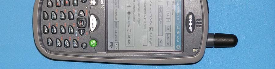
Click to zoom
Application Details
- Equipment Class
- DTS - Digital Transmission System
- Date of Grant
- Oct 19, 2004
- Application Purpose
- Original Equipment
- Date of Application
- Oct 19, 2004
- Equipment Note
- Hand held PC with WLAN
- Frequency Range
- 2412.00000000 - 2462.00000000
- Company
- Honeywell International Inc
- Country
- United States
Documents & Files
Document Text
Text extracted from the exhibit documents filed with the FCC. Open a document above to read the original.
Users Manual
™ User’s Guide - Prelim. Draft Rev (a) Dolphin ® 7900 Mobile Computer Windows Mobile™ 2003 Second Edition Software for Pocket PCs Disclaimer Hand Held Products, Inc. d/b/a HHP (“HHP”) reserves the right to make changes in specifications and other information contained in this document without prior notice, and the reader should in all cases consult HHP to determine whether any such changes have been made. The information in this publication does not represent a commitment on the part of HHP. HHP shall not be liable for technical or editorial errors or omissions contained herein; nor for incidental or consequential damages resulting from the furnishing, performance, or use of this material. This document contains proprietary information that is protected by copyright. All rights are reserved. No part of this document may be photocopied, reproduced, or translated into another language without the prior written consent of HHP. © 2004 Hand Held Products, Inc. All rights reserved. Web Address: www.hhp.com Trademarks Dolphin, HomeBase, Mobile Base, and QuadCharger are trademarks or registered trademarks of Hand Held Products, Inc. Windows Mobile, Windows, Windows NT, Windows 2000, Windows ME, Windows XP, ActiveSync, Outlook, and the Windows logo are trademarks or registered trademarks of Microsoft Corporation. Intel is a registered trademark of Intel Corporation. Chapter 9 (pages 9-1–9-11) contains copyrighted information from SyChip, Inc. Chapter 9 (pages 9-12–9-25) contains copyrighted information from Meetinghouse Corporation. Meetinghouse, the Meetinghouse logo, and all other Meetinghouse trademarks/service marks contained herein are trademarks or registered trademarks of Meetinghouse. Chapter 10 is copyrighted information used by permission from Bluetooth SIG, Inc. The Bluetooth trademarks are owned by Bluetooth SIG, Inc., U.S.A. and licensed to HHP. Chapter 11 (11-3–11-15 and 11-17–11-22) contains information with permission from INTRINSYC Software, Inc. Other product names mentioned in this manual may be trademarks or registered trademarks of their respective companies and are hereby acknowledged. Dolphin® 7900 Mobile Computer User’s Guide - Prelim. Draft Rev (a) iii Chapter 1 - Introduction Required Safety Labels ....................................................................................................................... 1-2 Location........................................................................................................................................ 1-2 Regulatory and Safety Approvals for all Dolphin 7900 Terminals ...................................................1-3 Dolphin 7900 WLAN or WPAN Radio ....................................................................................... 1-4 Dolphin 7900 WWAN Radio ....................................................................................................... 1-5 FCC Compliance................................................................................................................................. 1-6 Dolphin 7900 Batch Terminal ...................................................................................................... 1-6 Dolphin 7900 RF Terminal with 802.11b, Bluetooth, and/or GSM Radios ................................ 1-6 RF, Regulatory, and Safety Agency Approvals for 802.11b and Bluetooth ............................... 1-7 RF, Regulatory, and Safety Agency Approvals for GSM ........................................................... 1-7 Dolphin 7900 802.11b and/or Bluetooth R&TTE Compliance Statement .................................. 1-7 Dolphin 7900 GSM R&TTE Compliance Statement................................................................... 1-8 Pacemakers, Hearing Aids and Other Electrically Powered Devices .......................................... 1-8 Microwaves .................................................................................................................................. 1-8 Care and Cleaning of the Dolphin 7900 ............................................................................................. 1-8 Chapter 2 - Getting Started Overview............................................................................................................................................. 2-1 Dolphin 7900 Models......................................................................................................................... 2-2 Dolphin 7900 Peripherals ................................................................................................................... 2-3 Dolphin 7900 Accessories .................................................................................................................. 2-4 Using the Dolphin 7900 for the First Time......................................................................................... 2-5 Resetting the Terminal ...................................................................................................................... 2-11 Soft Reset (Warm Boot) ............................................................................................................. 2-11 Hard Reset (Cold Boot) .............................................................................................................. 2-11 Suspend Mode................................................................................................................................... 2-11 Chapter 3 - Dolphin 7900 Hardware Overview System Features .................................................................................................................................. 3-1 Front Panel Features ........................................................................................................................... 3-2 Back Panel Features ............................................................................................................................ 3-4 Side Panel Features ........................................…
Text truncated - open the document above for the full version.
Users Manual
Dolphin® 7900 Mobile Computer User’s Guide - Prelim. Draft Rev (a)11 - 1 11 Wireless WAN Communications with GSM/GPRS Overview Dolphin 7900 terminals can be configured with Wireless Wide Area Network (WWAN) via an integrated Siemens ® GSM/GPRS tri-band radio module. GSM - GSM stands for Global System for Mobile communications. It is an open, non-proprietary wireless wide area networking system that is constantly evolving and growing. One of its great strengths is international roaming capability, which provides standardized dialing in more than 170 countries. GPRS - GPRS stands for General Packet Radio Service. It is a non-voice value added service that allows packet switched data and information to be instantly sent and received across a mobile telephone network. Powering Up the GSM/GPRS Radio Driver When the mobile computer is first initialized, the radio driver for the GSM module is installed. Before using the radio, make sure that the GSM radio is powered up. For more information, see The Radio Manager on page 4-8. Tri-Band Antenna Requirements Using GMS/GPRS on a Dolphin 7900 terminal requires: • a network subscription to a GSM/GPRS network (you need to know what service providers are in your geographic area), and • a SIM card installed on the terminal. Capabilities Dolphin 7900 computers with integrated GSM/GPRS WWAN radios are optimized for the following two-way voice and data communications: • GSM voice data ("dial-up") • SMS (Short Message Service) text messages • GPRS Class 10 - data transmissions average. 40-60 Kbps (wireless network carrier dependent) Dolphin 7900 terminals configured with a GSM/GPRS radio feature a tri-band antenna that supports 900, 1800 and 1900 MHz frequencies for worldwide mobile applications. 11 - 2Dolphin® 7900 Mobile Computer User’s Guide - Prelim. Draft Rev (a) SIM Card Installation SIM stands for Subscriber Information Module. A SIM card stores the subscriber's personal information, GSM/GPRS radio settings, security key, contacts, etc. SIM cards can be installed and removed from compatible mobile devices, enabling you to switch devices without losing your personal information. SIM cards are obtained and activated by the network provider that supports your GSM/GPRS network. Requirements Before installing the SIM card: • The SIM card must be activated by the service provider. • The terminal must be powered down. To Install a SIM Card: On the Dolphin 7900 terminal, the access door is located on the left, side panel; see Side Panel Features on page 3-6. Note:The access door on the left side panel is not user-accessible in the field. A special Torx T8 tool from HHP is required to loosen the screws; HHP part number 100001024. 1. Obtain HHP part number 100001024. 2. Power down the terminal and lay it down on a flat surface. 3. Unscrew the faceplate of the access door. 4. Insert your SIM card. 5. Place the SIM card door over the secured SIM card. 6. Secure the faceplate. 7. Power on the terminal to verify that the SIM card is working. Note:If the SIM card is not installed properly, the Dialler screen will indicate that no SIM card is installed. Do NOT power on the device with the SIM card installed and the access door still open. You must secure the faceplate before you power on the device. Failure to do so will could result in damage to the terminal and will void the warranty. ! Dolphin® 7900 Mobile Computer User’s Guide - Prelim. Draft Rev (a)11 - 3 Using uPhone The uPhone Application Suite contains three programs that function together to provide a complete voice, data, and text messaging solution for a mobile device fitted with a radio modem: • Dialler emulates a mobile phone and is used to make and receive telephone calls - Using the Dialler, page 11-6. • Call Log enables you to view and manipulate a list of the most recent calls - Call Log, page 11-14. • SMS Manager provides a text message handler similar to many email programs - SMS Manager, page 11-16. Accessing uPhone Go to Start > Programs > uPhone. Tap one of the icons to launch the program. Navigation Bar When the Dialler or SMS Manager applications are not open, the icons in the Navigation bar at the top of the screen indicates the status of the phone and messaging system. Each icon indicates s specific action and, when tapped, displays a bubble window that lets you know what is happening. Status Icons and Bubble Options IconThis icon means...Tapping this icon displays this bubble:Bubble Options The phone is off. Tap Power Phone On to turn the phone on and close the bubble. Tap Hide to leave the phone off and close the bubble. The phone can only make emergency calls. This usually means there is no SIM card installed or PIN number established. Tap Hide to dismiss the bubble. This icon will appear in the Navigation bar until a SIM card is installed or a PIN is entered. 11 - 4Dolphin® 7900 Mobile Computer User’s Guide - Prelim. Draft Rev (a) The phone is registering on the network. Tap Hide to dismiss the bubble. This is a temporary state. This icon appears only until the phone is registered on the network. The phone is on and registered. To the right of the phone is a bar that indicates signal strength. Tap Hide to dismiss the bubble. Tap Power Phone Off to turn off the phone. The icon in the Navigation bar changes to indicate the phone is now off. Indicates medium signal strength. Indicates good signal strength. Indicates full signal strength. Incoming SMS message available. This bubble appears automatically when a new SMS message is received. It contains the sender’s information and the first line of the text message. Tap View to display the full message in SMS Manager. Tap Reply to switch to the SMS Manager Compose screen. The 'To:' field is auto-filled with the sender’s address. Tap Save to put the message in the SMS Manager Inbox. Tap Delete to delete the message. Tapping each button closes the bubble. A new voicemail message is available. This bubble appears automatically when a voicemail n…
Text truncated - open the document above for the full version.
External Photos
External Photos D7900 EUT – Front view External Photos D7900 EUT – Back view
ID Label/Location Info
A 500002817 RELEASE LABEL, 7900 802.11b 500002817 A ONE 21SEP04 S. MONROE 21SEP04 Notes :1. COLORS: PANTONE PROCESS WHITE: ALL OTHER GRAPHICSBACKGROUND: HHP BLUE GREY 500000002812 THESE DRAWINGS AND SPECIFICATIONS ARE THE PROPERTY AND CONFIDENTIALTHESE DRAWINGS AND SPECIFICATIONS ARE THE PROPERTY AND CONFIDENTIAL MATERIAL OF HAND HELD PRODUCTS, INC. AND SHALL NOT BEMATERIAL OF HAND HELD PRODUCTS, INC. AND SHALL NOT BE REPRODUCED, OR COPIED, OR USED AS A BASIS FOR MANUFACTURE OR SALEREPRODUCED, OR COPIED, OR USED AS A BASIS FOR MANUFACTURE OR SALE OF EQUIPMENT OR DEVICES WITHOUT WRITTEN PERMISSION. cOF EQUIPMENT OR DEVICES WITHOUT WRITTEN PERMISSION. c REV# REV DESCRIPTION REV DESCRIPTION DESIGNED BYDESIGNED BY DATE ARTWORK LEVEL ARTWORK LEVEL TITLE: A DRAWING NO:DRAWING NO: REV SCALE DO NOT SCALEDO NOT SCALE SHEET 1 OF 1 DRAWING NO. DRAWING NO. DATE ECN# 100000896 2. REFERENCE PRO-E DRAWING P9500031,REV B FOR DIE CUT AND MATERIAL SPECIFICATIONS SCALE 2X N10410 Tested to Comply With FCC StandardsThis Class B Digital apparatus complies with FOR HOME OR OFFICE USE Canadian ICES-003. Cet appariel numerique de la Classe B est conforme a la norme NMB-003 du Canada. Hand Held Products, Inc. www.hhp.com Made in USA of US &imported parts.No user serviceable parts. Opening Voids Warranty. 0682 ! Canada: 1C1693B79L00 FCC ID: HD57900L00 N10410 Tested to Comply With FCC StandardsThis Class B Digital apparatus complies with FOR HOME OR OFFICE USE Canadian ICES-003. Cet appariel numerique de la Classe B est conforme a la norme NMB-003 du Canada. Hand Held Products, Inc. www.hhp.com Made in USA of US &imported parts.No user serviceable parts. Opening Voids Warranty. 0682 ! Canada: 1C1693B79L00 FCC ID: HD57900L00 PRELIMINARY Label Location
RF Exposure Info
SAR Test Report No.: SAR_662_2004_FCC_2450 Date of Report: 10/6/2004 Appendix A Plots Page 1 of 3 System / software: SARA2 / 2.3 VPM Input Power Drift: Date / Time: 9/8/2004 1:54:23 PM DUT Battery Model/No: Filename: temp.txt Probe Serial Number: 0106 Ambient Temperature: 22.0°C Liquid Simulant: 2450 Device Under Test: HHP D7900 Relative Permittivity: 50.99 Relative Humidity: 50% Conductivity: 1.927 Phantom S/No: HeadBox_new_spout.c sv Liquid Temperature: 22.0°C Phantom Rotation: 0° Max SAR Y-axis Location: -57.00 mm DUT Position: body belt clip to phantom Max SAR Z-axis Location: -124.40 mm Antenna Configuration: Integral Max E Field: 8.65 V/m Test Frequency: 2412MHz SAR 1g: 0.112 W/kg Air Factors: 415 / 805 / 371 SAR 10g: 0.060 W/kg Conversion Factors: 0.585 / 0.585 / 0.585 SAR Start: 0.030 W/kg Type of Modulation: SAR End: 0.029 W/kg Modn. Duty Cycle: SAR Drift during Scan: -0.08 dB Diode Compression Factors (V*200): 19 / 19 / 19 Probe battery last changed: 7/22/2004 Input Power Level: maximum Extrapolation: poly4 SAR Test Report No.: SAR_662_2004_FCC_2450 Date of Report: 10/6/2004 Appendix A Plots Page 2 of 3 System / software: SARA2 / 2.3 VPM Input Power Drift: Date / Time: 9/8/2004 2:35:39 PM DUT Battery Model/No: Filename: 2412_3d.txt Probe Serial Number: 0106 Ambient Temperature: 22.0°C Liquid Simulant: 2450 Device Under Test: HHP D7900 Relative Permittivity: 51.16 Relative Humidity: 50% Conductivity: 1.942 Phantom S/No: HeadBox_new_spout.c sv Liquid Temperature: 22.0°C Phantom Rotation: 0° Max SAR Y-axis Location: -52.00 mm DUT Position: body belt clip to phantom Max SAR Z-axis Location: -126.00 mm Antenna Configuration: Integral Max E Field: 9.61 V/m Test Frequency: 2437MHz SAR 1g: 0.139 W/kg Air Factors: 415 / 805 / 371 SAR 10g: 0.074 W/kg Conversion Factors: 0.585 / 0.585 / 0.585 SAR Start: 0.036 W/kg Type of Modulation: SAR End: 0.037 W/kg Modn. Duty Cycle: SAR Drift during Scan: 0.16 dB Diode Compression Factors (V*200): 19 / 19 / 19 Probe battery last changed: 7/22/2004 Input Power Level: maximum Extrapolation: poly4 SAR Test Report No.: SAR_662_2004_FCC_2450 Date of Report: 10/6/2004 Appendix A Plots Page 3 of 3 System / software: SARA2 / 2.3 VPM Input Power Drift: Date / Time: 9/8/2004 3:13:29 PM DUT Battery Model/No: Filename: 2437_3d.txt Probe Serial Number: 0106 Ambient Temperature: 22.0°C Liquid Simulant: 2450 Device Under Test: HHP D7900 Relative Permittivity: 51.21 Relative Humidity: 50% Conductivity: 1.958 Phantom S/No: HeadBox_new_spout.c sv Liquid Temperature: 22.0°C Phantom Rotation: 0° Max SAR Y-axis Location: -56.00 mm DUT Position: body belt clip to phantom Max SAR Z-axis Location: -126.80 mm Antenna Configuration: Integral Max E Field: 7.78 V/m Test Frequency: 2462MHz SAR 1g: 0.092 W/kg Air Factors: 415 / 805 / 371 SAR 10g: 0.049 W/kg Conversion Factors: 0.585 / 0.585 / 0.585 SAR Start: 0.025 W/kg Type of Modulation: SAR End: 0.025 W/kg Modn. Duty Cycle: SAR Drift during Scan: 0.00 dB Diode Compression Factors (V*200): 19 / 19 / 19 Probe battery last changed: 7/22/2004 Input Power Level: maximum Extrapolation: poly4
RF Exposure Info
SAR Test Report No.: SAR_662_2004_FCC_2450 Date of Report: 10/06/2004 Appendix B Page 1 of 4 Appendix B: Photos EUT Photos: Photo 1. EUT front SAR Test Report No.: SAR_662_2004_FCC_2450 Date of Report: 10/06/2004 Appendix B Page 2 of 4 Photo 2. EUT back SAR Test Report No.: SAR_662_2004_FCC_2450 Date of Report: 10/06/2004 Appendix B Page 3 of 4 Setup Photos Photo 3 Belt clip touching phantom. SAR Test Report No.: SAR_662_2004_FCC_2450 Date of Report: 10/06/2004 Appendix B Page 4 of 4 Photo 4 Photo to demonstrate 15 cm Z-axis flat phantom
RF Exposure Info
SAR Test Report No.: SAR_662_2004_FCC_2450 Date of Report: 10/06/2004 Appendix C Page 1 of 36 1 Tissue Parameters 2450MHz Head liquid: Recipe: 53.74% distilled water 22.59% DGBE 22.59% triton X-100 0.98% salt 0.1% bactericide Di-electric constants measured on 9/8/2004. SAR measurements were made within 24 hours of the measurement of liquid parameters. Freq. Rel. Condy (MHz) Perm. (S/m) 2450 40.02 1.77 2450MHz Body Liquid: Recipe: 73.3% distilled water 12.88% DGBE 12.88% triton X-100 0.84% salt 0.1% bactericide Di-electric constants measured on 9/8/2004. SAR measurements were made within 24 hours of the measurement of liquid parameters. Freq. Rel. Condy (MHz) Perm. (S/m) 2412 50.99 1.927 2437 51.16 1.942 2462 51.21 1.958 Environment: 9/8/2004: Temperature: 20.1 °C – 23.9°C Humidity: 45% _ 55 % SAR Test Report No.: SAR_662_2004_FCC_2450 Date of Report: 10/06/2004 Appendix C Page 2 of 36 2 Test Equipment Instrument description Supplier / Manufacturer Model Serial No. Calibration (date) Calibration Due (date) Bench top Robot Mitsubishi supplied by IndexSAR RV-E2 EA1030108 N/A N/A SAM Phantom Upright shell phantom made by Antennessa digitized and mounted by IndexSAR SAM 03FT26 04/03 N/A Flat Phantom IndexSAR HeadBox_Spout N/A N/A N/A Software IndexSAR SARA2 v0.420 N/A N/A N/A 2450 MHz Head Tissue Simulant Cetecom Inc. 2450 Head N/A 9/8/2004 N/A 2450 MHz Body Tissue Simulant Cetecom Inc. 2450 Body N/A 9/8/2004 N/A 2450 MHz Dipole IndexSAR – IEEE 1528 design IXD-245 245-0016 07/20/2004 07/20/2005 Netwok Analyzer Agilent 8753ES US39172511 05/03/2004 05/03/2005 Directional coupler Werlatone C6529 11249 N/A N/A RF Amplifier Vectawave VTL5400 N/A N/A N/A Power Meter Rohde & Schwarz NRVD 836875/020 05/20/2004 05/20/2005 Power Sensor Rohde & Schwarz URV5-Z2 836029/034 05/20/2004 05/20/2005 Power Sensor Rohde & Schwarz URV5-Z2 836029/035 05/20/2004 05/20/2005 SAR Probe IndexSAR IXP-050 S/N 0106 7/15/2003 1/15/2005 Probe amplifier IndexSAR IXA-010 S/N 043 N/A N/A Thermometer Control Company 4039 20410549 11/20/2001 11/20/2004 Dielectric Measurement Kit IndexSAR Di-Line N/A N/A N/A Test Equipment Model Serial SAR Test Report No.: SAR_662_2004_FCC_2450 Date of Report: 10/06/2004 Appendix C Page 3 of 36 3 Equipment Calibration/Performance Documents: Validation Dipoles Performance Measurements: Pages 4 to 9. Immersible SAR probe Calibration Report: Pages 10 to 36 Please Note: (The following pages of Appendix C show calibration documents. These calibration documents are inserted into this appendix. The header information with page numbering scheme is a part of this report and is included on all pages of the report and appendixes. This header is used to track all of the contents of this report.) SAR Test Report No.: SAR_662_2004_FCC_2450 Date of Report: 10/06/2004 Appendix C Page 4 of 36 4 Report No. SN0016_090-180-245 July 1 st 2002 INDEXSAR Validation Dipoles Type IXD-090, IXD-180 & IXD-245 Performance measurements S/N: 090-0016 S/N: 180-0016 S/N: 245-0016 MI Manning Indexsar, Oakfield House, Cudworth Lane, Newdigate, Surrey RH5 5DR. UK. Tel: +44 (0) 1306 631233 Fax: +44 (0) 1306 631834 e-mail: [email protected] SAR Test Report No.: SAR_662_2004_FCC_2450 Date of Report: 10/06/2004 Appendix C Page 5 of 36 5 1. Measurement Conditions Measurements were performed using a box-shaped phantom made of PMMA with dimensions designed to meet the accuracy criteria for reasonably-sized phantoms that do not have liquid capacities substantially in excess of the volume of liquid required to fill the Indexsar upright SAM phantoms used for SAR testing of handsets against the ear. An HP 8753B vector network analyser was used for the return loss measurements. The dipole was placed in a special holder made of low-permittivity, low-loss materials. This holder enables the dipole to be positioned accurately in the centre of the base of the Indexsar box-phantom used for flat-surface testing and validation checks. The validation dipoles are supplied with special spacers made form a low-permittivity, low-loss foam material. These spacers are fitted to the dipole arms to ensure that, when the dipole is offered up to the phantom surface, the spacing between the dipole and the liquid surface is accurately aligned according to the guidance in the relevant standards documentation. The spacers are rectangular with a central hole equal to the dipole arm diameter and dimensioned so that the longer side can be used to ensure a spacing of 15mm from the liquid in the phantom (for tests at 900MHz and below) and the shorter side can be used for tests at 1800MHz and above to ensure a spacing of 10mm from the liquid in the phantom. The spacers are made on a CNC milling machine with an accuracy of 1/40 th mm but they may suffer wear and tear and need to be replaced periodically. The material used is Rohacell, which has a relative permittivity of approx. 1.05 and a negligible loss tangent. The apparatus supplied by Indexsar for dipole validation tests thus includes: Balanced dipoles for each frequency required are dimensioned according to the guidelines given in IEEE 1528 [1]. The dipoles are made from semi-rigid 50 ohm co-ax, which is joined by soldering and is gold-plated subsequently. The constructed dipoles are easily deformed, if mis-handled, and periodic checks need to be made of their symmetry. Rohacell foam spacers designed for presenting the dipoles to 2mm thick PMMA box phantoms. These components also suffer wear and tear and should be replaced when the central hole is a loose-fit on the dipole arms or if the edges are too worn to ensure accurate alignment. The standard spacers are dimensioned for use with 2mm wall thickness (additional spacers are available for 4mm wall thickness). 2. SAR Measurement SAR Test Report No.: SAR_662_2004_FCC_2450 Date of Report: 10/06/2004 Appendix C Page 6 of 36 6 SAR validation checks using the dipoles can be performed with the box-phantom located on the SARA2 phantom support base on the SARA2 robot sy…
Text truncated - open the document above for the full version.
RF Exposure Info
TTI-P-G 081/94-A0 Accredited according to ISO/IEC 17025 Bluetooth Qualification Test Facility (BQTF) FCC listed # 101450 IC recognized # 3925 CETECOM Inc. 411 Dixon Landing Road Milpitas, CA 95035 U.S.A. Phone: + 1 (408) 586 6200 Fax: + 1 (408) 586 6299 E-mail: [email protected] http://www.cetecom.com CETECOM Inc. is a Delaware Corporation with Corporation number: 2113686 Board of Directors: Dr. Harald Ansorge, Dr. Klaus Matkey, Hans Peter May V.2.16M-2002-03-12 \\stupendousman\rootappsdata\emc\projects_emc\hhp\662- 2004_d7900\sar\report\wlan\sar_662_2004_fcc_2450.doc © Copyright by CETECOM SAR Test Report No.: SAR_662_2004_FCC_2450 for the Hand Held Products, Inc. Hand held computer with 802.11b WLAN Model Number: D7900 FCC ID: HD57900L00 Date of Report: 10/06/2004 Date of issue: 10/06/2004 Report Copy No.: 01 SAR Test Report No. SAR_662_2004_FCC_2450 Date of Report: 10/06/2004 Page 2 of 24 Error! Reference source not found. This report shall not be reproduced except in full without the written approval of: CETECOM Inc. SAR 411 Dixon Landing Road Milpitas, CA 95035 U.S.A. Contents 1 ASSESSMENT ...................................................................................................................4 2 ADMINISTRATIVE DATA...................................................................................................5 2.1 Identification of the Testing Laboratory Issuing the SAR Assessment Report ...............5 2.2 Identification of the Client...........................................................................................5 2.3 Identification of the Manufacturer...............................................................................5 3 EQUIPMENT UNDER INVESTIGATION (EUI)...................................................................6 3.1 Identification of the Equipment under Investigation ...................................................6 3.2 Front View of the Equipment under Investigation ......................................................7 4 SUBJECT OF INVESTIGATION ........................................................................................8 4.1 The IEEE Standard C95.1 and the FCC Exposure Criteria .......................................8 4.2 Distinction Between Exposed Population, Duration of Exposure and Frequencies...8 4.3 Distinction between Maximum Permissible Exposure and SAR Limits......................9 4.4 SAR Limit ...................................................................................................................9 5 THE FCC MEASUREMENT PROCEDURE .....................................................................10 5.1 General Requirements.............................................................................................10 5.2 Body-worn and Other Configurations.......................................................................10 5.3 Procedure for assessing the peak spatial-average SAR .........................................11 5.4 Determination of the largest peak spatial-average SAR ..........................................13 6 THE MEASUREMENT SYSTEM ......................................................................................14 6.1 Robot system specification ......................................................................................14 6.2 Probe and amplifier specification .............................................................................15 6.3 Phantoms.................................................................................................................15 6.4 SAR measurement procedure .................................................................................16 6.5 SARA2 Interpolation and Extrapolation schemes ....................................................16 6.6 Interpolation of 2D area scan...................................................................................17 6.7 Extrapolation of 3D scan..........................................................................................17 6.8 Interpolation of 3D scan and volume averaging.......................................................17 SAR Test Report No. SAR_662_2004_FCC_2450 Date of Report: 10/06/2004 Page 3 of 24 Error! Reference source not found. This report shall not be reproduced except in full without the written approval of: CETECOM Inc. SAR 411 Dixon Landing Road Milpitas, CA 95035 U.S.A. 7 UNCERTAINTY ASSESSMENT.......................................................................................19 7.1 Table of Measurement Uncertainty Values of SAR Evaluations..............................20 7.2 Table of Measurement Uncertainty Values for SAR System Verification ................21 8 TEST RESULTS SUMMARY............................................................................................22 8.1 Conducted Output Power.........................................................................................22 8.2 Test Positions and Configurations ...........................................................................22 8.3 WLAN Operating Mode............................................................................................22 8.4 2450 MHz band SAR Results for D7900 .................................................................23 8.5 Validation Check Results .........................................................................................23 9 REFERENCES..................................................................................................................24 SAR Test Report No. SAR_662_2004_FCC_2450 Date of Report: 10/06/2004 Page 4 of 24 Error! Reference source not found. This report shall not be reproduced except in full without the written approval of: CETECOM Inc. SAR 411 Dixon Landing Road Milpitas, CA 95035 U.S.A. 1 Assessment The Hand Held Products, Inc. D7900 Hand held computer with 802.11b WLAN, FCC ID: HD57900L00, is in compliance with the limits for general population uncontrolled expos…
Text truncated - open the document above for the full version.
Test Report
TTI-P-G 081/94-A0 Accredited according to ISO/IEC 17025 Bluetooth Qualification Test Facility (BQTF) FCC listed # 101450 IC recognized # 3925 CETECOM Inc. 411 Dixon Landing Road Milpitas, CA 95035 U.S.A. Phone: + 1 (408) 586 6200 Fax: + 1 (408) 586 6299 E-mail: [email protected] http://www.cetecom.com CETECOM Inc. is a Delaware Corporation with Corporation number: 2113686 Board of Directors: Dr. Harald Ansorge, Dr. Klaus Matkey, Hans Peter May V1.1 2003-03-01 The BLUETOOTH trademarks are owned by Bluetooth SIG…
Text truncated - open the document above for the full version.
Contact Information
Applicant
Cindy Jiang(Global Regulatory Compliance Manager)
Test Firm
Cetecom ICT Services GmbHRalf Hoehn
Technical Specifications
| # | Rule Parts | Frequency Range | Power Output |
|---|---|---|---|
| 1 | 15C | 2.41 GHz - 2.46 GHz | 40.00 mW |
Other Applications from Honeywell International Inc
HD5-CT47HFUHF
Aug 04, 2026A rugged accessory for the Honeywell CT47 mobile computer which enables HF and UHF reading. Reader is supplied from mobile computer CT47.
Equipment Class
DXX - Part 15 Low Power Communication Device TransmitterHD5CT47HFUHF
Aug 04, 2026A rugged accessory for the Honeywell CT47 mobile computer which enables HF and UHF reading. Reader is supplied from mobile computer CT47.
Equipment Class
DTS - Digital Transmission SystemHD5-8680IC
Jun 17, 2026Barcode Scanner
Equipment Class
DSS - Part 15 Spread Spectrum TransmitterHD5-CT70X1
Jan 26, 2026Mobile Computer
Equipment Class
CBE - Citizens Band End User DevicesHD5-1972
Dec 25, 2025Barcode Scanner
Equipment Class
DSS - Part 15 Spread Spectrum Transmitter