HD57900L0PHand held PC with WLAN and BT
Honeywell International Inc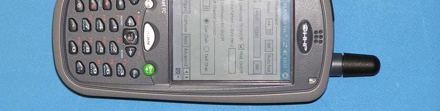
Click to zoom
Application Details
- Equipment Class
- DSS - Part 15 Spread Spectrum Transmitter
- Date of Grant
- Oct 19, 2004
- Application Purpose
- Original Equipment
- Date of Application
- Oct 19, 2004
- Equipment Note
- Hand held PC with WLAN and BT
- Frequency Range
- 2402.00000000 - 2480.00000000
- Company
- Honeywell International Inc
- Country
- United States
Documents & Files
Document Text
Text extracted from the exhibit documents filed with the FCC. Open a document above to read the original.
Users Manual
™ User’s Guide - Prelim. Draft Rev (a) Dolphin ® 7900 Mobile Computer Windows Mobile™ 2003 Second Edition Software for Pocket PCs Disclaimer Hand Held Products, Inc. d/b/a HHP (“HHP”) reserves the right to make changes in specifications and other information contained in this document without prior notice, and the reader should in all cases consult HHP to determine whether any such changes have been made. The information in this publication does not represent a commitment on the part of HHP. HHP shall not be liable for technical or editorial errors or omissions contained herein; nor for incidental or consequential damages resulting from the furnishing, performance, or use of this material. This document contains proprietary information that is protected by copyright. All rights are reserved. No part of this document may be photocopied, reproduced, or translated into another language without the prior written consent of HHP. © 2004 Hand Held Products, Inc. All rights reserved. Web Address: www.hhp.com Trademarks Dolphin, HomeBase, Mobile Base, and QuadCharger are trademarks or registered trademarks of Hand Held Products, Inc. Windows Mobile, Windows, Windows NT, Windows 2000, Windows ME, Windows XP, ActiveSync, Outlook, and the Windows logo are trademarks or registered trademarks of Microsoft Corporation. Intel is a registered trademark of Intel Corporation. Chapter 9 (pages 9-1–9-11) contains copyrighted information from SyChip, Inc. Chapter 9 (pages 9-12–9-25) contains copyrighted information from Meetinghouse Corporation. Meetinghouse, the Meetinghouse logo, and all other Meetinghouse trademarks/service marks contained herein are trademarks or registered trademarks of Meetinghouse. Chapter 10 is copyrighted information used by permission from Bluetooth SIG, Inc. The Bluetooth trademarks are owned by Bluetooth SIG, Inc., U.S.A. and licensed to HHP. Chapter 11 (11-3–11-15 and 11-17–11-22) contains information with permission from INTRINSYC Software, Inc. Other product names mentioned in this manual may be trademarks or registered trademarks of their respective companies and are hereby acknowledged. Dolphin® 7900 Mobile Computer User’s Guide - Prelim. Draft Rev (a) iii Chapter 1 - Introduction Required Safety Labels ....................................................................................................................... 1-2 Location........................................................................................................................................ 1-2 Regulatory and Safety Approvals for all Dolphin 7900 Terminals ...................................................1-3 Dolphin 7900 WLAN or WPAN Radio ....................................................................................... 1-4 Dolphin 7900 WWAN Radio ....................................................................................................... 1-5 FCC Compliance................................................................................................................................. 1-6 Dolphin 7900 Batch Terminal ...................................................................................................... 1-6 Dolphin 7900 RF Terminal with 802.11b, Bluetooth, and/or GSM Radios ................................ 1-6 RF, Regulatory, and Safety Agency Approvals for 802.11b and Bluetooth ............................... 1-7 RF, Regulatory, and Safety Agency Approvals for GSM ........................................................... 1-7 Dolphin 7900 802.11b and/or Bluetooth R&TTE Compliance Statement .................................. 1-7 Dolphin 7900 GSM R&TTE Compliance Statement................................................................... 1-8 Pacemakers, Hearing Aids and Other Electrically Powered Devices .......................................... 1-8 Microwaves .................................................................................................................................. 1-8 Care and Cleaning of the Dolphin 7900 ............................................................................................. 1-8 Chapter 2 - Getting Started Overview............................................................................................................................................. 2-1 Dolphin 7900 Models......................................................................................................................... 2-2 Dolphin 7900 Peripherals ................................................................................................................... 2-3 Dolphin 7900 Accessories .................................................................................................................. 2-4 Using the Dolphin 7900 for the First Time......................................................................................... 2-5 Resetting the Terminal ...................................................................................................................... 2-11 Soft Reset (Warm Boot) ............................................................................................................. 2-11 Hard Reset (Cold Boot) .............................................................................................................. 2-11 Suspend Mode................................................................................................................................... 2-11 Chapter 3 - Dolphin 7900 Hardware Overview System Features .................................................................................................................................. 3-1 Front Panel Features ........................................................................................................................... 3-2 Back Panel Features ............................................................................................................................ 3-4 Side Panel Features ........................................…
Text truncated - open the document above for the full version.
Users Manual
Dolphin® 7900 Mobile Computer User’s Guide - Prelim. Draft Rev (a)11 - 1 11 Wireless WAN Communications with GSM/GPRS Overview Dolphin 7900 terminals can be configured with Wireless Wide Area Network (WWAN) via an integrated Siemens ® GSM/GPRS tri-band radio module. GSM - GSM stands for Global System for Mobile communications. It is an open, non-proprietary wireless wide area networking system that is constantly evolving and growing. One of its great strengths is international roaming capability, which provides standardized dialing in more than 170 countries. GPRS - GPRS stands for General Packet Radio Service. It is a non-voice value added service that allows packet switched data and information to be instantly sent and received across a mobile telephone network. Powering Up the GSM/GPRS Radio Driver When the mobile computer is first initialized, the radio driver for the GSM module is installed. Before using the radio, make sure that the GSM radio is powered up. For more information, see The Radio Manager on page 4-8. Tri-Band Antenna Requirements Using GMS/GPRS on a Dolphin 7900 terminal requires: • a network subscription to a GSM/GPRS network (you need to know what service providers are in your geographic area), and • a SIM card installed on the terminal. Capabilities Dolphin 7900 computers with integrated GSM/GPRS WWAN radios are optimized for the following two-way voice and data communications: • GSM voice data ("dial-up") • SMS (Short Message Service) text messages • GPRS Class 10 - data transmissions average. 40-60 Kbps (wireless network carrier dependent) Dolphin 7900 terminals configured with a GSM/GPRS radio feature a tri-band antenna that supports 900, 1800 and 1900 MHz frequencies for worldwide mobile applications. 11 - 2Dolphin® 7900 Mobile Computer User’s Guide - Prelim. Draft Rev (a) SIM Card Installation SIM stands for Subscriber Information Module. A SIM card stores the subscriber's personal information, GSM/GPRS radio settings, security key, contacts, etc. SIM cards can be installed and removed from compatible mobile devices, enabling you to switch devices without losing your personal information. SIM cards are obtained and activated by the network provider that supports your GSM/GPRS network. Requirements Before installing the SIM card: • The SIM card must be activated by the service provider. • The terminal must be powered down. To Install a SIM Card: On the Dolphin 7900 terminal, the access door is located on the left, side panel; see Side Panel Features on page 3-6. Note:The access door on the left side panel is not user-accessible in the field. A special Torx T8 tool from HHP is required to loosen the screws; HHP part number 100001024. 1. Obtain HHP part number 100001024. 2. Power down the terminal and lay it down on a flat surface. 3. Unscrew the faceplate of the access door. 4. Insert your SIM card. 5. Place the SIM card door over the secured SIM card. 6. Secure the faceplate. 7. Power on the terminal to verify that the SIM card is working. Note:If the SIM card is not installed properly, the Dialler screen will indicate that no SIM card is installed. Do NOT power on the device with the SIM card installed and the access door still open. You must secure the faceplate before you power on the device. Failure to do so will could result in damage to the terminal and will void the warranty. ! Dolphin® 7900 Mobile Computer User’s Guide - Prelim. Draft Rev (a)11 - 3 Using uPhone The uPhone Application Suite contains three programs that function together to provide a complete voice, data, and text messaging solution for a mobile device fitted with a radio modem: • Dialler emulates a mobile phone and is used to make and receive telephone calls - Using the Dialler, page 11-6. • Call Log enables you to view and manipulate a list of the most recent calls - Call Log, page 11-14. • SMS Manager provides a text message handler similar to many email programs - SMS Manager, page 11-16. Accessing uPhone Go to Start > Programs > uPhone. Tap one of the icons to launch the program. Navigation Bar When the Dialler or SMS Manager applications are not open, the icons in the Navigation bar at the top of the screen indicates the status of the phone and messaging system. Each icon indicates s specific action and, when tapped, displays a bubble window that lets you know what is happening. Status Icons and Bubble Options IconThis icon means...Tapping this icon displays this bubble:Bubble Options The phone is off. Tap Power Phone On to turn the phone on and close the bubble. Tap Hide to leave the phone off and close the bubble. The phone can only make emergency calls. This usually means there is no SIM card installed or PIN number established. Tap Hide to dismiss the bubble. This icon will appear in the Navigation bar until a SIM card is installed or a PIN is entered. 11 - 4Dolphin® 7900 Mobile Computer User’s Guide - Prelim. Draft Rev (a) The phone is registering on the network. Tap Hide to dismiss the bubble. This is a temporary state. This icon appears only until the phone is registered on the network. The phone is on and registered. To the right of the phone is a bar that indicates signal strength. Tap Hide to dismiss the bubble. Tap Power Phone Off to turn off the phone. The icon in the Navigation bar changes to indicate the phone is now off. Indicates medium signal strength. Indicates good signal strength. Indicates full signal strength. Incoming SMS message available. This bubble appears automatically when a new SMS message is received. It contains the sender’s information and the first line of the text message. Tap View to display the full message in SMS Manager. Tap Reply to switch to the SMS Manager Compose screen. The 'To:' field is auto-filled with the sender’s address. Tap Save to put the message in the SMS Manager Inbox. Tap Delete to delete the message. Tapping each button closes the bubble. A new voicemail message is available. This bubble appears automatically when a voicemail n…
Text truncated - open the document above for the full version.
External Photos
External Photos D7900 EUT – Front view External Photos D7900 EUT – Back view
ID Label/Location Info
A 500002820 RELEASE LABEL, 7900 BLUETOOTHand 802.11b 500002820 A ONE 21SEP04 S. MONROE 21SEP04 Notes :1. COLORS: PANTONE PROCESS BLACK: BLUETOOTH SYMBOLPANTONE PROCESS WHITE: ALL OTHER GRAPHICSBACKGROUND: HHP BLUE GREY 500000002812 THESE DRAWINGS AND SPECIFICATIONS ARE THE PROPERTY AND CONFIDENTIALTHESE DRAWINGS AND SPECIFICATIONS ARE THE PROPERTY AND CONFIDENTIAL MATERIAL OF HAND HELD PRODUCTS, INC. AND SHALL NOT BEMATERIAL OF HAND HELD PRODUCTS, INC. AND SHALL NOT BE REPRODUCED, OR COPIED, OR USED AS A BASIS FOR MANUFACTURE OR SALEREPRODUCED, OR COPIED, OR USED AS A BASIS FOR MANUFACTURE OR SALE OF EQUIPMENT OR DEVICES WITHOUT WRITTEN PERMISSION. cOF EQUIPMENT OR DEVICES WITHOUT WRITTEN PERMISSION. c REV# REV DESCRIPTION REV DESCRIPTION DESIGNED BYDESIGNED BY DATE ARTWORK LEVEL ARTWORK LEVEL TITLE: A DRAWING NO:DRAWING NO: REV SCALE DO NOT SCALEDO NOT SCALE SHEET 1 OF 1 DRAWING NO. DRAWING NO. DATE ECN# 100000899 2. REFERENCE PRO-E DRAWING P9500031, REV B FOR DIE CUT AND MATERIAL SPECIFICATIONS SCALE 2X X ½X ½X ½X ½X 3. BLUETOOTH SYMBOL SHOULD CONTAIN A KEEP OUT AREA DEFINED AS A BOX ON EACH SIDE OF THE SYMBOL½ THE HEIGHT OF THE SYMBOL. THE BOX IS NOT PRINTED. N10410 Tested to Comply With FCC StandardsThis Class B Digital apparatus complies with FOR HOME OR OFFICE USE Canadian ICES-003. Cet appariel numerique de la Classe B est conforme a la norme NMB-003 du Canada. Hand Held Products, Inc. Made in USAof US &imported parts. No userserviceableparts. Opening VoidsWarranty. 0682 ! Canada: 1C1693B79L0P FCC ID: HD57900L0P www.hhp.com N10410 Tested to Comply With FCC StandardsThis Class B Digital apparatus complies with FOR HOME OR OFFICE USE Canadian ICES-003. Cet appariel numerique de la Classe B est conforme a la norme NMB-003 du Canada. Hand Held Products, Inc. Made in USAof US &imported parts. No userserviceableparts. Opening VoidsWarranty. 0682 ! Canada: 1C1693B79L0P FCC ID: HD57900L0P www.hhp.com PRELIMINARY Label Location
Internal Photos
FCC ID: LUBBTM-1 EUT PHOTO Solder Side FCC ID: LUBBTM-1 EUT PHOTO Component Side FCC ID: LUBBTM-1 EUT PHOTO EUT Mounted on carrier PCB FCC ID: LUBBTM-1 EUT PHOTO (Shield Removed)
Test Report
TTI-P-G 081/94-A0 Accredited according to ISO/IEC 17025 Bluetooth Qualification Test Facility (BQTF) FCC listed # 101450 IC recognized # 3925 CETECOM Inc. 411 Dixon Landing Road Milpitas, CA 95035 U.S.A. Phone: + 1 (408) 586 6200 Fax: + 1 (408) 586 6299 E-mail: [email protected] http://www.cetecom.com CETECOM Inc. is a Delaware Corporation with Corporation number: 2113686 Board of Directors: Dr. Harald Ansorge, Dr. Klaus Matkey, Hans Peter May V1.1 2003-03-01 The BLUETOOTH trademarks are owned by Bluetooth SIG, Inc., U.S.A. and licensed to CETECOM Inc. © Copyright by CETECOM FCC Test Report Test report no.: EMC_662FCC15.247_2004_BT FCC Part 15.247 for FHSS systems / CANADA RSS-210 Model: 7900L0P FCC ID: HD57900L0P IC: 1693B79L0P Test report no.: EMC_662FCC15.247_2004_BT_7900L0P Issue date: 2004-10-04 Page 2 (37) Table of Contents 1 General information 1.1 Notes 1.2 Testing laboratory 1.3 Details of applicant 1.4 Application details 1.5 Test item 1.6 Test standards 2 Technical test 2.1 Summary of test results 2.2 Test report 1 General information 1.1 Notes The test results of this test report relate exclusively to the test item specified in 1.5. The CETECOM Inc. USA does not assume responsibility for any conclusions and generalizations drawn from the test results with regard to other specimens or samples of the type of the equipment represented by the test item. The test report may only be reproduced or published in full. Reproduction or publication of extracts from the report requires the prior written approval of the CETECOM Inc USA. TEST REPORT PREPARED BY: EMC Engineer: Harpreet Sidhu 1.2 Testing laboratory CETECOM Inc. 411 Dixon Landing Road, Milpitas, CA-95035, USA Phone: +1 408 586 6200 Fax: +1 408 586 6299 E-mail: [email protected] Internet: www.cetecom.com Test report no.: EMC_662FCC15.247_2004_BT_7900L0P Issue date: 2004-10-04 Page 3 (37) 1.3 Details of applicant Name : Hand Held Products, Inc. Street : 700 Vision Drive City / Zip Code : Skaneateles Falls, NY 13153 Country : U.S.A Contact : Naveen Velagapudi Telephone : +1 315 685 2931 Tele-fax : +1 315 685 1210 e-mail : [email protected] 1.4 Application details Date of receipt test item : 2004-08-16 Date of test : 2004-08-16/17/18 1.5 Test item Manufacturer : Applicant Marketing Name : D7900 Model No. : 7900L0P Description : Hand held computer with BT and WLAN FCC-ID : HD57900L0P IC ID : 1693B79L0P Additional information Test Sample for BT : s/n 32598 Frequency : 2402MHz – 2480MHz for BT Type of modulation : GFSK Number of channels : 79 Antenna : Internal Power supply : Battery or Charger (AC Adaptor) Output power : -11.4dBm (0.00007W) max. conducted peak power 1.6 Test standards: FCC Part 15 §15.247 (DA00-705) / RSS 210 Note: All radiated measurements were made in all three orthogonal planes. The values reported are the maximum values. Test report no.: EMC_662FCC15.247_2004_BT_7900L0P Issue date: 2004-10-04 Page 4 (37) PROJECT OVERVIEW: NOTE: This test report covers all radiated measurements as per FCC15.247 for BT module in HHP handheld computer model#7900L0P. For all conducted measurements please refer to test report# BT_cond_Socket. Test report no.: EMC_662FCC15.247_2004_BT_7900L0P Issue date: 2004-10-04 Page 5 (37) 2 Technical test 2.1 Summary of test results No deviations from the technical specification(s) were ascertained in the course of the tests Performed Final Verdict: (only “passed” if all single measurements are “passed”) Passed Technical responsibility for area of testing: 2004-10-04 EMC & Radio Lothar Schmidt (Manager) Date Section Name Signature Responsible for test report and project leader: 2004-10-04 EMC & Radio Harpreet Sidhu (EMC Engineer) Date Section Name Signature Test report no.: EMC_662FCC15.247_2004_BT_7900L0P Issue date: 2004-10-04 Page 6 (37) 2.2 Test report TEST REPORT Test report no.: EMC_662FCC15.247_2004_BT_7900L0P Test report no.: EMC_662FCC15.247_2004_BT_7900L0P Issue date: 2004-10-04 Page 7 (37) TEST REPORT REFERENCE LIST OF MEASUREMENTS PAGE MAXIMUM PEAK OUTPUT POWER § 15.247 (b) (1) 8 BAND EDGE COMPLIANCE §15.247 (c) 13 CONDUCTED EMISSIONS § 15.107/207 28 RECEIVER SPURIOUS RADIATION § 15.209 30 TEST EQUIPMENT AND ANCILLARIES USED FOR TESTS 35 BLOCK DIAGRAMS 36 Test report no.: EMC_662FCC15.247_2004_BT_7900L0P Issue date: 2004-10-04 Page 8 (37) MAXIMUM PEAK OUTPUT POWER § 15.247 (b) (1) (CONDUCTED) TEST CONDITIONS MAXIMUM PEAK OUTPUT POWER (dBm) Frequency (MHz) Error! Reference source not found. Error! Reference source not found. Error! Reference source not found. T nom (23)°C V nom -13.6 -12.7 -11.4 Measurement uncertainty ±0.5dBm RBW/VBW: 3 MHz LIMIT SUBCLAUSE § 15.247 (b) (1) Frequency range RF power output 2400-2483.5 MHz 1.0 Watt conducted Test report no.: EMC_662FCC15.247_2004_BT_7900L0P Issue date: 2004-10-04 Page 9 (37) MAXIMUM PEAK OUTPUT POWER § 15.247 (b) (1) (RADIATED) EIRP : TEST CONDITIONS MAXIMUM PEAK OUTPUT POWER (dBm) Frequency (MHz) Error! Reference source not found. Error! Reference source not found. Error! Reference source not found. T nom (23)°C V nom -19.99 -21.63 -22.65 Measurement uncertainty ±0.5dBm RBW/VBW: 3 MHz LIMIT SUBCLAUSE § 15.247 (b) (1) Frequency range RF power output 2400-2483.5 MHz 1.0 Watt conducted Test report no.: EMC_662FCC15.247_2004_BT_7900L0P Issue date: 2004-10-04 Page 10 (37) -50 -40 -30 -20 -10 0 10 Level [dBm] 2.397G2.4G2.402G2.404G2.407G Frequency [Hz] Marker: 2.402190381 GHz -19.99 dBm PEAK OUTPUT POWER (RADIATED) §15.247 (b) (1) Lowest Channel: Error! Reference source not found.MHz SWEEP TABLE: "EIRP BT low channel" Short Description: EIRP Bluetooth channel-2402MHz Start Stop Detector Meas. IF Frequency Frequency Time BW 2.397GHz 2.407GHz MaxPeak Coupled 3 MHz Test report no.: EMC_662FCC15.247_2004_BT_7900L0P Issue date: 2004-10-04 Page 11 (37) -50 -40 -30 -20 -10 0 10 Level [dBm] 2.436G2.438G2.44G2.442G2.444G2.446G Frequency [Hz] Marker: 2.440488978 GHz -21.63 dBm PEAK OUTPUT POWER (RADIATED) §15.247 (b) (1) Mid C…
Text truncated - open the document above for the full version.
Test Report
EMCE Engineering, Inc., 44366 S. Grimmer Blvd., Fremont, CA 94538 Page 1 of 31 Tel:510-490-4307 Fax: 510-490-3441 e-mail: [email protected] Accredited by the National Voluntary Laboratory Accreditation Program for the specific scope of Accreditation under Lab Code 200092-0 FCC Part 15 (Subpart C – Intentional Radiators) Test Report Dated: 3/17/03 Prepared For: Socket Communications 34700 Central Court Newark, CA Model: Bluetooth Module Prepared by: EMCE Engineering, Inc. 44366 S. Grimmer Blvd. Fremont, CA 94538 USA EMCE Engineering, Inc., 44366 S. Grimmer Blvd., Fremont, CA 94538 Page 2 of 31 Tel:510-490-4307 Fax: 510-490-3441 e-mail: [email protected] Accredited by the National Voluntary Laboratory Accreditation Program for the specific scope of Accreditation under Lab Code 200092-0 CONTENTS 1. CUSTOMER INFORMATION 3 2. EUT AND ACCESSORY INFORMATION 4 2.1 EUT DESCRIPTION 4 2.2 EUT AND ACCESSORIES 4 2.3 SOFTWARE 4 3. SUMMARY OF TEST RESULTS 5 4. STANDARDS AND MEASUREMENT METHODS 6 4.1 SELECTION OF OPERATION MODE FOR TESTS 6 5. TEST SETUPS 6 5.1 SETUP A (CONDUCTED MEASUREMENTS, HOPPING ENABLED – INQUIRY MODE) 6 5.1.1 Operational description 6 5.1.2 Block Diagram 6 5.2 SETUP B (CONDUCTED MEASUREMENTS, HOPPING ENABLED) 7 5.2.1 Operational description 7 5.2.2 Block Diagram 7 5.3 SETUP C (RADIATED MEASUREMENTS, HOPPING ENABLED) 7 5.3.1 Operational description 7 5.3.2 Block Diagram 7 6. TEST RESULTS 8 6.1 PEAK OUTPUT POWER (CFR 47, §15.247B1) 8 6.1.1 EUT operation mode 8 6.1.2 Limits and results 8 6.1.3 Screen shots 9-11 6.2 CF SEPARATION [CFR 47, 15.247 (a) (1)] 12 6.2.1 Limits and results 12 6.2.2 Screen Shots 13 6.3 NUMBER OF HOPPING FREQUENCIES [CFR 47, 15.247 (a) (1) (ii)] 13 6.3.1 Limits and results 13 6.3.2 Screen Shots 14 6.4 DWELL TIME 14 6.4.1 Limits and results 15 6.4.2 Screen Shots 15-16 6.5 20dB BANDWIDTH 16 6.5.1 Limits and results 16 6.5.2 Screen shots 17-19 6.6 BAND-EDGE COMPLIANCE OF RF RADIATED EMISSIONS (CFR 47, §15.247C1) 19 6.6.1 EUT operation mode 19 6.6.2 Limits and results 20 6.6.3 Screen Shots 20-23 6.6.3.1 Test Method 23 6.7 RESTRICTED BAND RADIATED EMISSIONS (§15.247C) 23 6.7.1 EUT operation mode 23 6.7.2 Limits and results 24 6.7.3 Screen Shots 24-25 6.8 SPURIOUS RADIATED EMISSIONS (§15.247C1) 25 6.8.1 Test method and level, 30MHz - 1GHz 26 6.8.2 Test method and level, 1GHz - 18GHz 26-27 6.8.3 EUT operation mode 28 6.8.4 Radiated Emissions Measurement setup 29 6.8.5 Emission Measurement Data 30MHz-1GHz 29-30 7. TEST EQUIPMENT 31 EMCE Engineering, Inc., 44366 S. Grimmer Blvd., Fremont, CA 94538 Page 3 of 31 Tel:510-490-4307 Fax: 510-490-3441 e-mail: [email protected] Accredited by the National Voluntary Laboratory Accreditation Program for the specific scope of Accreditation under Lab Code 200092-0 1 CUSTOMER INFORMATION Test Laboratory: FCC registration number EMCE Engineering 44366 S. Grimmer Blvd. Fremont, CA 94538 USA Tel: 510-490-4307 Fax: 510-490-3441 [email protected] 0007-1981-20 Customer: Socket Communications 34700 Central Court Newark, CA Tel: 510-744-2723 Fax: 510-744-2727 Contact Person: Charles Ader Receipt of EUT: 2/18/03 Test plan reference: FCC Part 2, 15 (15.247) Date of testing: 2/20/03-2/22/03 Date of Report: 3/1/03 The tests listed in this report have been done to demonstrate compliance to the CFR 47 Section 15.247. Contents approved: Name: Bob Cole Title: President Name Title EMCE Engineering, Inc., 44366 S. Grimmer Blvd., Fremont, CA 94538 Page 4 of 31 Tel:510-490-4307 Fax: 510-490-3441 e-mail: [email protected] Accredited by the National Voluntary Laboratory Accreditation Program for the specific scope of Accreditation under Lab Code 200092-0 2 EUT AND ACCESSORY INFORMATION 2.1 EUT description The EUT is a Socket Bluetooth Module 2.2 EUT and accessories The table below lists all EUTs and accessories used in the tests. Later in this report, only numbers in the last column are used to refer to the devices in each test. 2.3 Software The computers were equipped with test software provided by the customer. The software was used to control the EUT in the tests. Name Type S/N Number EUT “Socket BT Module” Bluetooth Module N/A E0001 Accessories Laptop Computer Fujitsu Lifebook M/N: CP15331 R3105476 S0001 Software CSR Bluesuite Bluetest N/A N/A EMCE Engineering, Inc., 44366 S. Grimmer Blvd., Fremont, CA 94538 Page 5 of 31 Tel:510-490-4307 Fax: 510-490-3441 e-mail: [email protected] Accredited by the National Voluntary Laboratory Accreditation Program for the specific scope of Accreditation under Lab Code 200092-0 3 SUMMARY OF TEST RESULTS Section in CFR 47 Results 15.247 (a)(2) (b)(1) Peak output power (Radiated Emissions) PASSED 15.247 (a)(1) Carrier Frequency Separation PASSED 15.247 (a)(1)(iii) Number of Hopping Frequencies PASSED 15.247 (a)(1)(iii) Dwell Time PASSED 15.247 (a)(1)(ii) 20 dB Bandwidth PASSED 15.247, (a)(5)(c) Band-edge compliance of RF Radiated emissions PASSED 15.247, (a)(5)(c) Restricted Band (Radiated Emissions) PASSED 15.249,(a) Spurious radiated emissions PASSED PASS The EUT passed that particular test. FAIL The EUT failed that particular test. EMCE Engineering, Inc., 44366 S. Grimmer Blvd., Fremont, CA 94538 Page 6 of 31 Tel:510-490-4307 Fax: 510-490-3441 e-mail: [email protected] Accredited by the National Voluntary Laboratory Accreditation Program for the specific scope of Accreditation under Lab Code 200092-0 4 STANDARDS AND MEASUREMENT METHODS The tests were performed in guidance of CFR 47 Part 15, Subpart C, FCC Public Notice DA 00-705 (March 30, 2000), and ANSI C63.4 (1992). Deviations, modifications or clarifications (if any) to above mentioned documents are written in each section under “Test method”. For the test equipment, see device list in the end of this test. 4.1 Selection of operation mode for tests Before tests, several operation modes, and modulation patterns were tried. The worst case was selected for each test and those results reported. 5 …
Text truncated - open the document above for the full version.
Test Setup Photos
Test setup photos D7900 Test setup – Radiated Emissions Test setup photos D7900 Test setup – AC Line Conducted Emissions
Contact Information
Applicant
Cindy Jiang(Global Regulatory Compliance Manager)
Test Firm
Cetecom ICT Services GmbHRalf Hoehn
Technical Specifications
| # | Rule Parts | Frequency Range | Power Output |
|---|---|---|---|
| 1 | 15C | 2.40 GHz - 2.48 GHz | 70.00 µW |
Other Applications from Honeywell International Inc
HD5-CT47HFUHF
Aug 04, 2026A rugged accessory for the Honeywell CT47 mobile computer which enables HF and UHF reading. Reader is supplied from mobile computer CT47.
Equipment Class
DXX - Part 15 Low Power Communication Device TransmitterHD5CT47HFUHF
Aug 04, 2026A rugged accessory for the Honeywell CT47 mobile computer which enables HF and UHF reading. Reader is supplied from mobile computer CT47.
Equipment Class
DTS - Digital Transmission SystemHD5-8680IC
Jun 17, 2026Barcode Scanner
Equipment Class
DSS - Part 15 Spread Spectrum TransmitterHD5-CT70X1
Jan 26, 2026Mobile Computer
Equipment Class
CBE - Citizens Band End User DevicesHD5-1972
Dec 25, 2025Barcode Scanner
Equipment Class
DSS - Part 15 Spread Spectrum Transmitter