HDOS619BTBLUETOOTH SPEAKER
Gemlink Ltd.
Click to zoom
Application Details
- Equipment Class
- DSS - Part 15 Spread Spectrum Transmitter
- Date of Grant
- Jun 22, 2014
- Application Purpose
- Original Equipment
- Date of Application
- Jun 22, 2014
- Equipment Note
- BLUETOOTH SPEAKER
- Frequency Range
- 2402.00000000 - 2480.00000000
- Company
- Gemlink Ltd.
- Country
- Hong Kong
Documents & Files
Document Text
Text extracted from the exhibit documents filed with the FCC. Open a document above to read the original.
Users Manual
Bluetooth Speaker User’s Guide for Model No. ISB65B Power Switch Pairing Button Carry Handle Using the Audio Input Requires a 3.5mm audio cable (not included). 1. Connect a 3.5mm audio cable to the Line In Input on the unit and the audio output on an audio device or home computer. The Pairing/Line In Indicator will display a solid blue light. 2. Use the native controls on the connected device to play your audio through the unit. LIne In BLuetootH FeatureS and ControLS Pairing Status/ Line In Indicator Charging Status Indicator Charging - RED Charged - Off Low Batt - Flashing Line In INCLUDES • Micro-USB cable FEATURES • Built-in Bluetooth speaker • 3.5mm audio input • Pairing button • On/off switch • Wireless range: 33 feet • DC battery power: built-in rechargeable lithium ion battery • Battery life: approx. 2.5 hours dC Power Input To power the speaker using the DC Power Input, use a Micro-USB cable (included) to connect to a USB power adapter or a USB port on a home computer. Pairing a Bluetooth Device for the First Time 1. Slide the power switch to on, and press and hold the Pair button. The Pairing Indicator will display a rapidly flashing blue light. When pairing, remain within 3 feet of the unit. 2. Using the native controls on your Bluetooth device, select the ISB65B in your Bluetooth settings to pair. If your device requests a password, enter the default password 0 0 0 0 . Refer to the user’s manual for your specific device for instructions on pairing and connecting Bluetooth devices. After initial pairing, the unit will stay paired unless unpaired manually by the user or erased due to a reset of the device. 3. When successfully paired and connected, a beep will issue from the unit and the Pairing/Line in Indicator will display a solid blue light. If your device should become unpaired or you find it is unable to connect, repeat the above steps. Playing Audio Wirelessly 1. To play or pause a selected track, use the native controls on the connected Bluetooth Device. 2. Audio played through the connected Bluetooth device will now be heard through the speaker. ISB65B-1035-01-IB.indd 16/6/2014 10:24:46 AM FCC ID:HDOS619BT Important Safety Instructions • Read these Instructions. • Keep these Instructions. • Heed all Warnings. • Follow all instructions. • Do not use this apparatus near water. • Clean only with a dry cloth. • Do not block any ventilation openings. Install in accordance with the manufacturer’s instructions. • Do not install near any heat sources such as radiators, heat registers, stoves, or other apparatus (including amplifiers) that produce heat. • Do not defeat the safety purpose of the polarized or grounding - type plug. A polarized plug has two blades with one wider than the other. A grounding type plug has two blades and a third grounding prong. The wide blade or the third prong are provided for your safety. When the provided plug does not fit into your outlet, consult an electrician for replacement of the obsolete outlet. • Protect the power cord from being walked on or pinched particularly at plugs, convenience receptacles, and the point where they exit from the apparatus. • Only use attachments/accessories specified by the manufacturer. • Unplug this apparatus during lightning storms or when unused for long periods of time. • Refer all servicing to qualified service personnel. Servicing is required when the apparatus has been damaged in any way, such as power-supply cord or plug is damaged, liquid has been spilled or objects have fallen into the apparatus, the apparatus has been exposed to rain or moisture, does not operate normally, or has been dropped. • Use only with a cart, stand, tripod, bracket, or table specified by the manufacturer, or sold with the apparatus. When a cart is used, use caution when moving the cart/apparatus combination to avoid injury from tip-over. FCC Warnings Additional Warnings and Precautions • CAUTION: TO PREVENT ELECTRIC SHOCK, MATCH WIDE BLADE OF PLUG TO WIDE SLOT, FULLY INSERT. • WARNING: To reduce the risk of fire or electric shock, do not expose this apparatus to rain, moisture, dripping, or splashing. Avis: Pour réduire le risque d’incendie ou de choc électrique, ne pas exposer cet appareil sous la pluie et l’humidité. • CAUTION: Use of controls or adjustments or performance of procedures other than those specified may result in hazardous radiation exposure. • WARNING: Changes or modifications to this unit not expressly approved by the party responsible for compliance could void the user’s authority to operate the equipment. • WARNING: Do not place this unit directly onto furniture surfaces with any type of soft, porous, or sensitive finish. As with any rubber compound made with oils, the feet could cause marks or staining where the feet reside. We recommend using a protective barrier such as a cloth or a piece of glass between the unit and the surface to reduce the risk of damage and/or staining. • WARNING: Use of this unit near fluorescent lighting may cause interference regarding use of the remote. If the unit is displaying erratic behavior move away from any fluorescent lighting, as it may be the cause. • CAUTION: Danger of explosion if battery is incorrectly replaced. Replace only with the same or equivalent type. Avis: Danger d’explosion si les piles sont remplacées de façon incorrect. Remplacer les piles seulement par le même type de pile ou l’équivalent. • WARNING: There is a danger of explosion if you attempt to charge standard Alkaline batteries in the unit. Only use rechargeable NiMH batteries. • WARNING: The remote control’s button cell battery contains mercury. Do not put in the trash, instead recycle or dispose of as hazardous waste • WARNING: Lithium batteries, like all rechargeable batteries, are recyclable and should be recycled or disposed of in normal household waste. Contact your local government for disposal or recycling practices in your area. They should never be incinerated since they might explode. • WAR…
Text truncated - open the document above for the full version.
Cover Letter(s)
Jun.19, 2014 Federal Communication Commission Authorization and Evaluation Division FCC ID: HDOS619BT Re: Confidentiality Request Pursuant to Sections 0.457 and 0.459 of the Commission’s Rules, the applicant hereby requests confidential treatment of information applied this application as outlined below: 1: Block Diagram 2: Circuit Diagram 3: Parts List 4.Operational Description The above materials contain trade secrets and proprietary information not customarily released to the public. The public disclosure of these matters might be harmful to the applicant and provide unjustified benefits to its competitors. The Applicant understands that pursuant to Rules 0.457, disclosure of this Application and all accompanying documentation will not be made before the date of the Grant for this application. Sincerely, Gemlink Ltd. Contact person: Keen Kwok Title: Engineer
External Photos
External Photos TOP VIEW OF EUT BOTTOM VIEW OF EUT FRONT VIEW OF EUT BACK VIEW OF EUT LEFT VIEW OF EUT RIGHT VIEW OF EUT
ID Label/Location Info
FCC ID/IC Label Location Model name:ISB65B Brand name:iLIVE FCC ID: HDOS619BT SB65R, ISB65G, ISB65BU, ISB64B, ISB64R, ISB64G, ISB64BU, B-19, B-19A CAWA
Internal Photos
Internal Photos OPEN VIEW OF EUT-1 OPEN VIEW OF EUT-2 INTERNAL VIEW OF EUT-1 INTERNAL VIEW OF EUT-2 INTERNAL VIEW OF EUT-2 BT Antenna
Test Report
Report No.: AGC01732140601FE03 Page 1 of 67 FCC Test Report Report No.: AGC01732140601FE03 FCC ID : HDOS619BT APPLICATION PURPOSE : Original Equipment PRODUCT DESIGNATION : BLUETOOTH SPEAKER BRAND NAME : iLIVE, CAWA MODEL NAME : ISB65B, SB65R, ISB65G, ISB65BU, ISB64B, ISB64R, ISB64G, ISB64BU, B‐19, B‐19A CLIENT : Gemlink Ltd. DATE OF ISSUE : Jun.18, 2014 STANDARD(S) : FCC Part 15 Rules REPORT VERSION : V1.0 Attestation of Global Compliance (Shenzhen) Co., Ltd CAUTION: This report shall not be reproduced except in full without the written permission of the test laboratory and shall not be quoted out of context. Report No.: AGC01732140601FE03 Page 2 of 67 Report Revise Record Report Version Revise Time Issued Date Valid VersionNotes V1.0 / Jun.18, 2014Valid Original Report Report No.: AGC01732140601FE03 Page 3 of 67 TABLE OF CONTENTS 1. VERIFICATION OF CONFORMITY ...................................................................................... 5 2. GENERAL INFORMATION .................................................................................................. 6 2.1. PRODUCT DESCRIPTION ........................................................................................................... 6 2.2. TABLE OF CARRIER FREQUENCYS .......................................................................................... 6 2.3. RECEIVER INPUT BANDWIDTH ................................................................................................. 7 2.4. EXAMPLE OF A HOPPING SEQUENCY IN DATA MODE ........................................................... 7 2.5. EQUALLY AVERAGE USE OF FREQUENCIES AND BEHAVIOUR ............................................ 7 2.6. RELATED SUBMITTAL(S) / GRANT (S) ....................................................................................... 8 2.7. TEST METHODOLOGY................................................................................................................ 8 2.8. SPECIAL ACCESSORIES ............................................................................................................ 8 2.9. EQUIPMENT MODIFICATIONS ................................................................................................... 8 3. MEASUREMENT UNCERTAINTY........................................................................................ 9 4. DESCRIPTION OF TEST MODES ........................................................................................ 9 5. SYSTEM TEST CONFIGURATION .................................................................................... 10 5.1. CONFIGURATION OF EUT SYSTEM ........................................................................................ 10 5.2. EQUIPMENT USED IN EUT SYSTEM ....................................................................................... 10 5.3. SUMMARY OF TEST RESULTS ................................................................................................ 10 6. TEST FACILITY .................................................................................................................. 11 7. PEAK OUTPUT POWER .................................................................................................... 12 7.1. MEASUREMENT PROCEDURE ................................................................................................ 12 7.2. TEST SET-UP (BLOCK DIAGRAM OF CONFIGURATION) ....................................................... 12 7.3. LIMITS AND MEASUREMENT RESULT .................................................................................... 13 8. 20DB BANDWIDTH ............................................................................................................ 19 8.1. MEASUREMENT PROCEDURE ................................................................................................ 19 8.2. TEST SET-UP (BLOCK DIAGRAM OF CONFIGURATION) ....................................................... 19 8.3. LIMITS AND MEASUREMENT RESULTS .................................................................................. 19 9. CONDUCTED SPURIOUS EMISSION ............................................................................... 26 9.1. MEASUREMENT PROCEDURE ................................................................................................ 26 9.2. TEST SET-UP (BLOCK DIAGRAM OF CONFIGURATION) ....................................................... 26 9.3. MEASUREMENT EQUIPMENT USED ....................................................................................... 26 9.4. LIMITS AND MEASUREMENT RESULT .................................................................................... 26 10. RADIATED EMISSION ..................................................................................................... 30 10.1. MEASUREMENT PROCEDURE .............................................................................................. 30 10.2. TEST SETUP ............................................................................................................................ 32 10.3. TEST RESULT .......................................................................................................................... 33 Report No.: AGC01732140601FE03 Page 4 of 67 11. BAND EDGE EMISSION .................................................................................................. 39 11.1. MEASUREMENT PROCEDURE .............................................................................................. 45 11.2. TEST SET-UP ........................................................................................................................... 45 11.3. TEST RESULT .......................................................................................................................... 46 12. NUMBER OF HOPPING FREQUENCY ............................................................................ 50 12.1. MEASUREMENT PROCEDURE ..............................................................................…
Text truncated - open the document above for the full version.
Test Setup Photos
APPENDIX IV PHOTOGRAPHS OF TEST SETUP FCC LINE CONDUCTED EMISSION TEST SETUP FCC RADIATED EMISSION TEST SETUP
Contact Information
Applicant
Keen Kwok
Test Firm
Attestation of Global Compliance Shenzhen Co. Ltd.Forrest Lei
Technical Specifications
| # | Rule Parts | Frequency Range | Power Output |
|---|---|---|---|
| 1 | 15C | 2.40 GHz - 2.48 GHz | 4.00 mW |
Other Applications from Gemlink Ltd.
HDOW189PBT
Feb 08, 2015HD Sound Bar with Bluetooth Wireless
Equipment Class
DSS - Part 15 Spread Spectrum Transmitter
HDOWM218BT
Jan 07, 20152 PACK INDOOR OUTDOOR BLUETOOTH SPEAKERS
Equipment Class
DSS - Part 15 Spread Spectrum Transmitter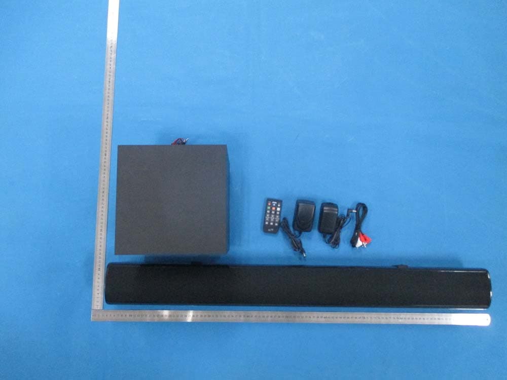
HDO2812SWBT
Jul 22, 2014Bluetooth 37 inch Sound bar with Subwoofer
Equipment Class
DSS - Part 15 Spread Spectrum Transmitter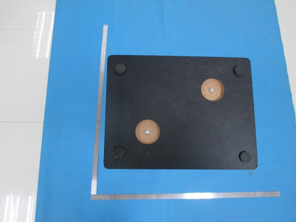
HDO134HMBT
May 05, 2014Bluetooth Tower Speaker
Equipment Class
DSS - Part 15 Spread Spectrum Transmitter
HDO298IBT
Jan 16, 2014Dual Portable Bluetooth Speakers
Equipment Class
DSS - Part 15 Spread Spectrum Transmitter