HED018WN3301FPCMCIA Wireless LAN ard
Accton Technology Corp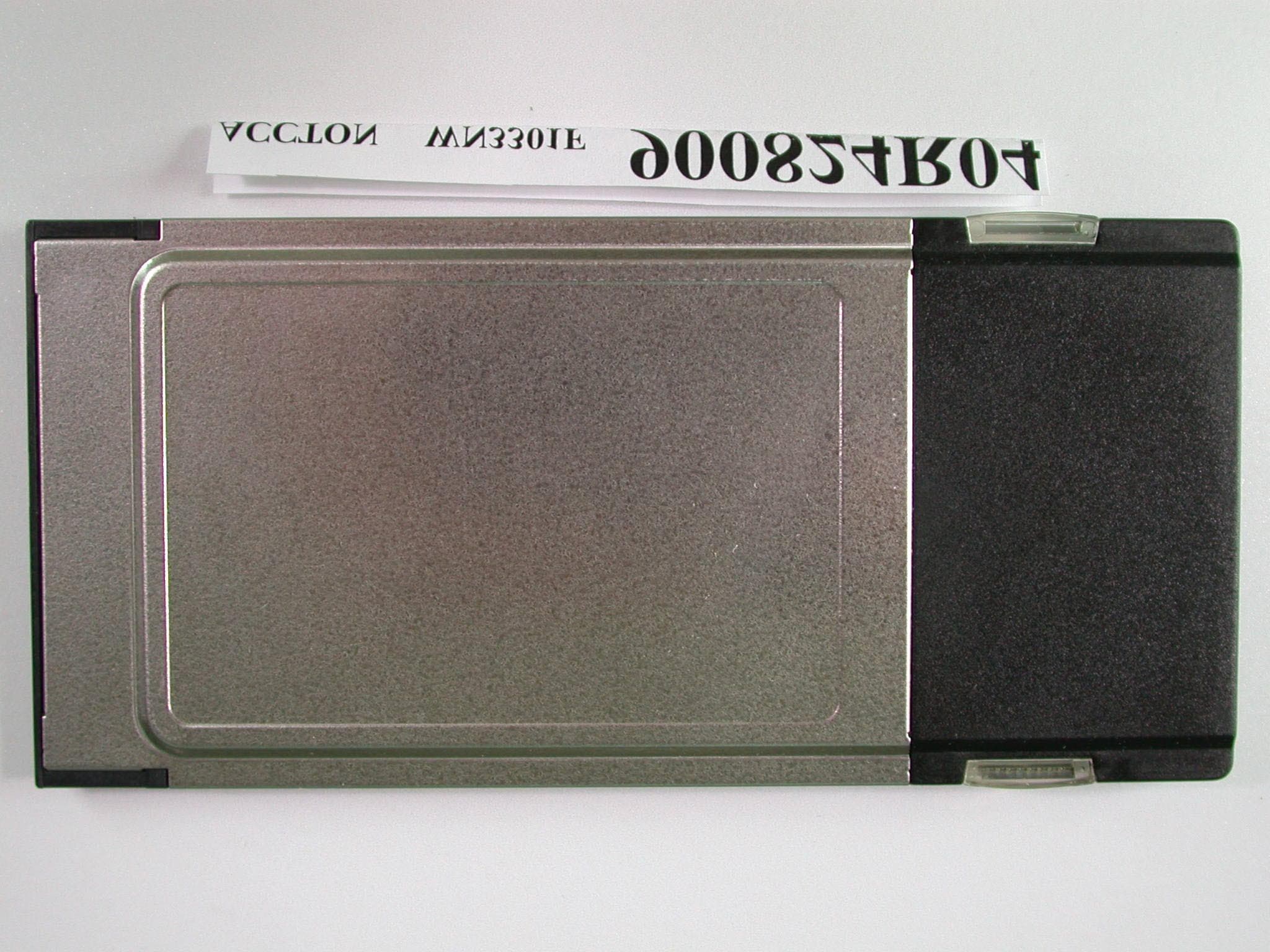
Click to zoom
Application Details
- Equipment Class
- DTS - Digital Transmission System
- Date of Grant
- Sep 25, 2001
- Application Purpose
- Original Equipment
- Date of Application
- Sep 25, 2001
- Equipment Note
- PCMCIA Wireless LAN ard
- Frequency Range
- 2412.00000000 - 2462.00000000
- Company
- Accton Technology Corp
- Country
- Taiwan
Documents & Files
Document Text
Text extracted from the exhibit documents filed with the FCC. Open a document above to read the original.
Users Manual
W W N N 3 3 3 3 0 0 1 1 F F Wireless LAN PCMCIA Adapter USER MANUAL Version 0.9.2, August 16, 2001 2 Federal Communications Commission Statement This device complies with FCC Rules Part 15. Operation is subject to the following two conditions: This device may not cause harmful interference. This device must accept any interference received, including interference that may cause undesired operation. This equipment has been tested and found to comply with the limits for a Class B digital device, pursuant to Part 15 of the FCC Rules. These limits are designed to provide reasonable protection against harmful interference in a residential installation. This equipment generates, uses and can radiate radio frequency energy. If this equipment is not installed and used in accordance with the manufacturer's instructions, it may cause harmful interference to radio communications. However, there is no guarantee that interference will not occur in a particular installation. If this equipment does cause harmful interference to radio or television reception, which can be determined by during the equipment off and on, the user is encouraged to try to correct the interference by one or more of the following measures: ß Reorient or relocate the receiving antenna. ß Increase the separation between the equipment and receiver. ß Connect the equipment to an outlet on a circuit different from that to which the receiver is connected. ß Consult the dealer or an experienced radio/TV technician for help. The use of shielded cables for connection of the monitor to the graphics card is required to assure compliance with FCC regulations. Changes or modifications to this unit not expressly approved by the party responsible for compliance could void the user's authority to operate this equipment. Manufacturer's Disclaimer Statement The information in this document is subject to change without notice and does not represent a commitment on the part of the vendor. No warranty or representation, either expressed or implied, is made with respect to the quality, accuracy or fitness for any particular purpose of this document. The manufacturer reserves the right to make changes to the content of this document and/or the products associated with it at any time without obligation to notify any person or organization of such changes. In no event will the manufacturer be liable for direct, indirect, special, incidental or consequential damages arising out of the use or inability to use this product or documentation, even if advised of the possibility of such damages. This document contains materials protected by copyright. All rights are reserved. No part of this manual may be reproduced or transmitted in any form, by any means or for any purpose without expressed written consent of its authors. Product names appearing in this document are mentioned for identification purchases only. All trademarks, product names or brand names appearing in this document are registered property of their respective owners. This device requires a radio license, unless it (including antenna) is installed totally inside a building. (User must obtain this license from Industry Canada). Printed in Taiwan 3 Contents Chapter 1 About the WN3301F PCMCIA Card.......................................................4 1-1 Features.................................................................................................................................................4 1-2 Applications............................................................................................................................................4 1-3 Product Kit..............................................................................................................................................5 Chapter 2 Network Configuration and Planning...................................................6 2-1 Network Topology..................................................................................................................................6 2-2 Roaming.................................................................................................................................................8 Chapter 3 Adapter Installation and Configuration – Windows ® 98........................9 3-1 System Requirements............................................................................................................................9 3-2 Inserting the Adapter..............................................................................................................................9 3-3 WN3301F Driver Installation -Windows ® 98........................................................................................10 3-4 Adapter Configuration – Windows ® 98.................................................................................................13 3-5 Protocol Installation – Windows ® 98....................................................................................................19 3-6 WN3301F Setup for Windows NT 4.0..................................................................................................24 Chapter 4 Installing and Navigating the PRISM Configuration Utility.................28 4-1 PRISM Configuration Utility - Installation.............................................................................................28 4-2 PRISM Configuration Utility- Navigation..............................................................................................31 Appendix A Troubleshooting.............................................................................36 Appendix B Glossary.........................................................................................38 4 Chapter 1 About the WN3301F PCMCIA Card The WN3301 IEEE 802.11 PCMCIA PC Card is compatible with any standard, notebook computer Type II or Type III PCMCIA slot. As a Plug-and-Play device, Windows 95/98 will automatically recognize the WN3301 PCMCIA card and initiate the insta…
Text truncated - open the document above for the full version.
Users Manual
19 3-5 PROTOCOL INSTALLATION – WINDOWS ® 98 Before continuing with the Protocol installation consult your System Administrator for details about your specific network. To install network protocols complete the following steps. 1. From the “Control Panel” double-click the “Network” icon. 2. Select “PRISM2 IEEE 902.11 PC Card Adapter” and click “Add”. 3. Highlight “Protocol” and click “Add” 20 4. Select “Microsoft” from the list of “Manufacturers” and “TCP-IP” from the list of “Network Protocols”, click “OK” 5. Select “TCP/IP “ and click “Properties”. Repeat step 2 – 5 to install other protocols such as Notebook or IPX/SPX. NOTE: The following steps apply to DHCP servers. Consult your system administrator for specific information regarding your server type, and for help in specifying an IP address if you do not use a DHCP server and must manually enter the IP address and DNS number. 21 6. Check “Obtain an IP address...” and click “OK”. If you are using a DHCP server the IP address will be entered automatically. 7. From the Network menu highlight “Client from Microsoft Networks”, and click" File and Print Sharing”. 22 8. Check both boxes and click “OK”. 9. Enter a “Computer name”, “Workgroup” and “Computer Description”, click “OK” 23 10. Enter a “Computer name”, “Workgroup” and “Computer Description”, click “OK” 11. You will be prompted to restart your computer, click “Yes” to complete the installation. Note: Please see the trouble shooting if you encounter some problem while installing the PC- Card card or your PC-Card is non-functional. 24 3-6 WN3301F SET UP FOR WINDOWS NT 4.0 Login as Administrator 1. From the desktop, select “Control Panel”, double-click “Network”, click “Adapters”, click “Add” 2. Click “Have Disk” 3. Insert the WN3301F disk; Windows NT will manually enter the path to the driver click “OK”. 25 4. Select your adapter from the list click “OK”. 5. Click “Close” from the “Network” dialog, Windows NT will auto-bind the new adapter with any network protocols already installed on the system. 26 6. After the auto-binding procedure is complete, select “Properties” from the “Network” dialog. At this point you may choose to manually specify an IP address, or automatically obtain an IP address if you are using a DHCP server. Consult your Systems Administrator for information about your server type, IP address settings and DNS number. 7. After the settings configuration is complete, confirm that the “Computer Name” and “Workgroup” designations are correct, and click “OK”.
Users Manual
27 8. You will be prompted to restart your computer, click yes to complete the installation 9. Upon restart, open the “Devices” menu from the “Control Panel”, to confirm that the driver installation was successful. Your adapters driver should now be listed in the “Devices” menu. 28 Chapter 4 Installing & Navigating the PRISM Configuration Utility 4-1 PRISM CONFIGURATION UTILITY - INSTALLATION 1. Insert the PRISM Network Configuration Utility disk into an available floppy disk drive. From the "Run" window type "A:\Utility\Setup.exe" (where "A" represents a floppy disk drive). 2. Click “Yes” to accept the License Agreement and continue with the installation. 3. Click “Next”. 29 4. Enter the System ID click “Next”. 5. Choose the Network Mode, click “Next” 6. Browse to install the utility in another folder, or confirm the installation and click “Next”. 30 7. You will be prompted to insert Disk 2. Insert the disk and click “Browse”. Double-click the “Setup” folder; double-click again on the “setup” icon. When the path has been automatically entered in the “Setup Needs The Next Disk” dialog, click “OK”. 8. After installation is complete, you will be prompted to restart your computer. Check “Yes” and click “Finish” to complete the installation and begin navigating the PRISM Configuration Utility. 31 4-2 PRISM CONFIGURATION UTILITY- NAVIGATION The following section describes and defines the various functions of the PRISM Network Configuration Utility. This utility provides quick access to all adapter settings. PRISM Quick-Launch Icon: After installation is complete, a PRISM utility icon will appear in the “Quick-Launch” menu in the lower right hand corner of the screen, near the clock. The PRISM Configuration Utility: Double clicking the PRISM icon in the Quick Launch bar will open the PRISM Configuration Utility main menu, providing quick access to all adapter settings. The following image shows the PRISM Configuration Utility with the “About” tab selected, here you will find Version, Copyright and Manufacturer information. 32 Link Info: The Link Info menu provides information about the current link between the adapter and the base station. Configuration: Selecting this tab opens the “Configuration” menu. Here you will find options for configuring your adapter. Description of Settings Following is an explanation of each adapter setting presented by the “Configuration” menu. Mode: The Mode setting determines the architecture of your wireless LAN. Choose Ad-Hoc or Infrastructure Mode depending on your network type. A brief explanation of each mode follows: ß Ad-Hoc: This mode is used for a simple peer-to-peer network. This type of network allows the sharing of local resources only between wireless clients without a wireless Access Point (AP). 33 ß Infrastructure: This mode allows a wireless LAN to be integrated into an existing wired network through an AP. Infrastructure type networks also permit roaming between Access Points while maintaining connection to all network resources. Infrastructure mode provides additional features, such as WEP security, power saving and extended range. SSID: An acronym for Service Set Identifier, SSID is the unique name shared among all clients and Access Points in a wireless network. The SSID must be identical for all clients or Access Points participating in the same network. The SSID is case sensitive and must not exceed 30 characters. Ethernet Conversion: The RFC1042 mode is the 802.11 standard conversion method and is selected by default. If compatibility with older wireless LAN systems is necessary select another conversion implementation from the Ethernet Conversion drop down list. TX Rate: The transmit rate or TX Rate selects the allowable transfer rates of the wireless client. To optimize performance and range, the TX Rate should be set to Fully Automatic, which will automatically adjust the transfer speed for best performance and longest range. Note: the AP must support The TX rate setting. If the AP does not support the TX rate, undesired results may occur. WEP: An acronym for Wired Equivalent Privacy, WEP is an encryption scheme used to protect your wireless data communications. WEP uses a combination of 40-bit keys to provide access control to your network and encryption security for every data transmission. To decode a data transmission, each wireless client on the network must use an identical 40-bit key. NOTE: This feature is only available in Infrastructure Mode and must also be enabled on the Access Point. Select the WEP tab to enable or disable this feature. PS Mode: Power Saving Mode enables or disables the power saving features of your wireless adapter. When enabled on a laptop, the power saving mode can reduce power consumption by the wireless card and extend the battery life of your laptop. This setting is only implemented in a network operating in Infrastructure mode. ß Changing the PS mode: The PS Mode on your adapter is set to “Disabled” by default. To change the setting, select “Enabled” from the drop-down list, click “OK” and wait a few seconds. The screen will then is updated and show the current Connection Status, Link Quality and Signal Strength. Channel: This setting specifies the default 802.11 channels used by the Wireless LAN communication. In an Infrastructure type network without an Access Point active on the default channel, clients will scan through all available channels searching for a network with matching SSID. ß Changing the Channel: Changing the channel is only effective in Ad-Hoc networks. Networks operating in Infrastructure mode automatically scan for a channel. The following table presents contains the operational channel frequency for several countries. 34 Regulatory Channel Frequency ChannelFrequency (MHZ) FCCCanadaETSIFranceSpainJapan 12412 22417 32422 42427 52432 62437 72442 82447 92452 102457 112462 122467 132472 142484 Encryption: Selecting the Encryption tab allows you to create new WEP keys. The 40-bit WEP key…
Text truncated - open the document above for the full version.
External Photos
Page 1 ANNEX PHOTOGRAPHS OF EUT Page 2
ID Label/Location Info
FCC ID Location
Internal Photos
Page 3 Page 4 Page 5
Operational Description
FCC ID: HED018WN3301F ADT No.900824R04 Operational Description The transmitter of the EUT (IEEE 802.11b 11Mbps Wireless LAN Card) is powered by notebook and plugged in PCMCIA Slot. The antenna is PCB Patch antenna, and there is no antenna connector. Under normal use condition, the user has to keep at least 20cm separation distance between radiator and the body of the user. The other instruction, please have a look at the users manual. DSSS Information This device is Direct Sequence Spread Spectrum, the data is mixed by pseudorandom code which is an orthogonal code. The mixed data is digital modulated by BPSK and QPSK technique depends on the data rates. The CCK coding is applied for increasing the data rate, and also the processing gain will be increased. The bit rates are 1,2,5.5,11Mbps, the symbol rates are 1,1,1.375,1.375Mbps, the chip rates are always 11Mbps. So, the Chip/symbol is 11,11,8 and 8 respectively. Although is higher bit rate, the processing gain is lower than 10, but the CCK coding used in higher bit rate will provide 2.2dB coding gain.
RF Exposure Info
55 44 33 22 11 E E D D C C B B A A SLIDE LQFP44 10V 10V 10V NNICHICON WN3301F T1.4 ACCTON Tec hnology Inc. C 33 Thursday, August 23, 2001 TitleSize Document Number Rev Date: Sheet of +3.3V VCCA VCCB VCCB 5V VCCB C305 22P L3002.2NH(0603) 12 R305470R(0603) 12 C306 100PF C308 100PF C307 100PF L30133NH(coil)0805 12 U8AS179-92 1 2 34 5 6 OUT GND OUTV1 IN V2 ANT1ANTENNA 1 ANT2ANTENNA 1 TR301FMMT718 C28A10P TR3002N3904 R30010K(0603) 1 2 R3021K(0603) 1 2 C30410PF(0603) R303100K(0603) 12 R3040R(1206) 1 2 C3030.1UF R65 1.5K C63 0.01UF C977P + C30210UF/16V 12 C69 7P C50 1000P C420.1UF C23 1000P C115N/F(1.5PF) R48100R R18100R C83 7P C1170.1UF C1140.01UF C94 100P C410.1UF C111 7P R7790.9R C870.5PF + C3810UF C92 0.01UF C797P R7682.5R C600.01UF L1433NH C610.01UF R73 20R R43100R C22 0.01UF C1180.068UF R3611.5K + C4310UF C99 0.01UF C1300.01UF C1230.68UF C47 220P U14 ENFVZ5F81 1 23 4 5 7 8 6 G VCCVCONT G G G G G C3622P C139NC C667P C301 N/F(7pF) R35 100 C9622P C86 0.01UF C300 10PF(0603) C309 7PF C310N/F(1.5PF)0603 R301 10K(0603) 12 C597P C787P C1250.01UF C777P R441.1K R38 9.53K R31 100 C68 7P C49 4.7P U16 UPC2745TB 1 2 3 4 5 6 IN G G OUT G VCC R39 1.1K C950.01UF R51 100R R25 100 R7590.9R C583.3P FL4MDR642E 1 2 3 4 G OUT G IN U10AS179-92 1 2 34 5 6 OUT GND OUTV1 IN V2 FL3MDR742F 1 2 3 4 G OUT G IN C140NC C487P C6522P L7 1.2NH C74 220P C65A 1P C624.7P C677P C75 4.7P C1161000P C1097P C2822P R17100R U11ISL3685IR 123456789 1011 12 13 14 15 16 17 18 19 20 21 22 2324252627282930313233 34 35 36 37 38 39 40 41 42 43 44 45 LAN_VCC1GNDRX_INBIAS1_VCC1H/LPE2PE1TX_VCC1GNDTXA_OUTGND TX_VCC1 TXA_IN GND LE DATA CLK REF_BY REF_IN SYN_VCC2 CP_VCC2 CD_D0 TX_MX_VCC1 TX_MX_OUT TX_MX_VCC1 TX_LO_DRIVER_VCC1 LO_IN+ LO_IN- LO_VCC1 RX_LO_DRIVER_VCC1 GND TX_MX_IN- RX_MX_OUT- RX_MX_OUT+ TX_MX_IN+ RX_MX_IN PRE_VCC1 ITAT_RES1 PTAT_RES BIAS2_VCC1 ITAT_RES2 RF_OUT GND COL_OUT PADDLE C400.1UF + C129 10UFL1233NH C16 0.01UF R37 1.5K R69649 C65B1P C28B0.5P C77A 7PC501 0.01UF L50 33NH(0603) 12 CASE GND J1 MM8430-2600 Female 180 度 IN OUT J2MMCX(F) 1 U300MA02303GJ 1234 5678 Vd1 RF in/Vg1 GND Vg2 Vg3GNDRF out/Vd3Vd2 J3MMCX(F) 1 U7AME8801CEEV 3 2 1 5 4 SHDN GND IN OUT BP LE_RF TX_DET ANTSEL* IF- RX_RF_AGCIF+ PE1 SCLK_RF_IF T/R_SW* PE2 44MHZ_CW T/R_SW SD_RF_IF ANTSEL PA_PE
RF Exposure Info
FCC ID: HED018WN3301F ADT No.: 900824R04 FCC TEST REPORT REPORT NO.: RF900824R04 MODEL NO.: WN3301F ACCORDING: FCC Guidelines for Human Exposure IEEE C95.1 APPLICANT:Accton Technology Corporation ADDRESS: No.1, Creation Rd.3, Science-based Industrial Park, Hsinchu, Taiwan, R.O.C. ISSUED BY:Advance Data Technology Corporation LAB LOCATION:47 14th Lin, Chiapau Tsun, Linko, Taipei, Taiwan, R.O.C. 0528 Lab Code: 200102-0 FCC ID: HED018WN3301F ADT No.: 900824R04 RF Exposure Measurement (Mobile Device) 1. Introduction 2.4 GHz frequency band is regarded specially as a dangerous band for its heating harmfulness to the human body. That’s why microwave oven is operating in this frequency band. The manufacturer whose product is working in this frequency band is obligatory to prove the harmfulness of his product. In this document, we try to prove the safety of radiation harmfulness to the human body for our product. The limit for Maximum Permissible Exposure (MPE) specified in FCC 1.1310 is followed. The Gain of the antenna used in this product is measured in a Fully Anechoic Chamber (FAC), and the maximum total power input to the antenna is measured. Through the Friis transmission formula and the maximum gain of the antenna, we can calculate the distance, away from the product, where the limit of MPE is reached. 2. Classification The antenna of the product, under normal use condition, is at least 20 cm away from the body of the user. Warning statement for keeping 20 cm separation distance and the prohibition of operating next to a person has been printed on the users manual. So, this product is classified as the Mobile Device. 3. RF Exposure Limit According to FCC 1.1310: The criteria listed in the following table shall be used to evaluate the environmental impact of human exposure to radio-frequency (RF) radiation as specified in 1.1307(b). FCC ID: HED018WN3301F ADT No.: 900824R04 LIMITS FOR MAXIMUM PERMISSIBLE EXPOSURE (MPE) Frequency Range (MHz) Electric Field Strength (V/m) Magnetic Field Strength (A/m) Power Density (mW/cm 2 ) Average Time (minutes) (A)Limits For Occupational / Control Exposures 30-30061.40.1631.06 300-1500......F/3006 1500-100,000......56 (B)Limits For General Population / Uncontrolled Exposure 30-30027.50.0730.230 300-1500......F/150030 1500-100,000......1.030 F = Frequency in MHz 4. Friis Formula Friis transmission formula : Pd = (Pout*G) / (4*pi*r 2 ) where Pd = power density in mW/cm 2 Pout = output power to antenna in mW G = gain of antenna in linear scale Pi = 3.1416 R = distance between observation point and center of the radiator in cm Pd is the limit of MPE, 1 mW/cm 2 . If we know the maximum Gain of the antenna and the total power input to the antenna, through the calculation, we will know the distance r where the MPE limit is reached. Ref. : David K. Cheng, Field and Wave Electromagnetics, Second Edition, Page 640, Eq. (11-133). 5. EUT Operating condition The software provided by Manufacturer enabled the EUT to transmit and receive data at lowest, middle and highest channel individually. FCC ID: HED018WN3301F ADT No.: 900824R04 6. Test Results 6.1 Antenna Gain The maximum Gain measured in Fully Anechoic Chamber is -1 dBi or 0.79 (numeric). 6.2 Output Power Into Antenna & RF Exposure Distance : CHANNEL CHANNEL FREQUENCY (MHz) OUTPUT POWER TO ANTENNA (mW) MINIMUM ALLOWABLE DISTANCE ( r ) FROM SKIN (Centi-Meter) 1241263.392.00 6243763.392.00 11246265.312.03 The minimum allowable distance is very close to the enclosure of the antenna and is very far away from the human being under normal use condition.
Test Report
FCC ID: HED018WN3301F Report No.: RF900824R04 1 Issued: Sep. 7, 2001 FCC TEST REPORT REPORT NO.: RF900824R04 MODEL NO.: WN3301F RECEIVED: August 24, 2001 TESTED: August 29~ August 31, 2001 APPLICANT: Accton Technology Corporation ADDRESS: No.1, Creation Rd. 3, Science-based Industrial Park, Hsinchu, Taiwan, R.O.C. ISSUED BY: Advance Data Technology Corporation LAB LOCATION: 47 14th Lin, Chiapau Tsun, Linko, Taipei, Taiwan, R.O.C. This test report consists of 48 pages in total. It may be duplicated completely for legal use with the approval of the applicant. It should not be reproduced except in full, without the written approval of our laboratory. The client should not use it to claim product endorsement by CNLA, NVLAP or any government agencies. The test results in the report only apply to the tested sample. 0528 Lab Code: 200102-0 FCC ID: HED018WN3301F Report No.: RF900824R04 2 Issued: Sep. 7, 2001 Table of Contents 1CERTIFICATION ........................................................................................... 4 2SUMMARY OF TEST RESULTS ................................................................... 5 3GENERAL INFORMATION............................................................................ 6 3.1GENERAL DESCRIPTION OF EUT.............................................................. 6 3.2DESCRIPTION OF TEST MODES ................................................................ 7 3.3GENERAL DESCRIPTION OF APPLIED STANDARDS ............................... 7 3.4DESCRIPTION OF SUPPORT UNITS .......................................................... 8 4TEST TYPES AND RESULTS ....................................................................... 9 4.1CONDUCTED EMISSION MEASUREMENT ................................................ 9 4.1.1LIMITS OF CONDUCTED EMISSION MEASUREMENT .............................. 9 4.1.2TEST INSTRUMENTS................................................................................... 9 4.1.3TEST PROCEDURES ................................................................................. 10 4.1.4TEST SETUP .............................................................................................. 10 4.1.5EUT OPERATING CONDITIONS ................................................................ 11 4.1.6TEST RESULTS .......................................................................................... 12 4.2RADIATED EMISSION MEASUREMENT ................................................... 18 4.2.1LIMITS OF RADIATED EMISSION MEASUREMENT ................................. 18 4.2.2TEST INSTRUMENTS................................................................................. 19 4.2.3TEST PROCEDURES ................................................................................. 20 4.2.4TEST SETUP .............................................................................................. 21 4.2.5EUT OPERATING CONDITIONS ................................................................ 21 4.2.6TEST RESULTS .......................................................................................... 22 4.36DB BANDWIDTH MEASUREMENT .......................................................... 26 4.3.1LIMITS OF 6dB BANDWIDTH MEASUREMENT ........................................ 26 4.3.2TEST INSTRUMENTS................................................................................. 26 4.3.3TEST PROCEDURE.................................................................................... 27 4.3.4TEST SETUP .............................................................................................. 27 4.3.5EUT OPERATING CONDITIONS ................................................................ 27 4.3.6TEST RESULTS .......................................................................................... 28 4.4MAXIMUM PEAK OUTPUT POWER .......................................................... 32 4.4.1LIMITS OF MAXIMUM PEAK OUTPUT POWER MEASUREMENT ........... 32 4.4.2TEST INSTRUMENTS................................................................................. 32 4.4.3TEST PROCEDURES ................................................................................. 33 4.4.4TEST SETUP .............................................................................................. 33 4.4.5EUT OPERATING CONDITIONS ................................................................ 33 FCC ID: HED018WN3301F Report No.: RF900824R04 3 Issued: Sep. 7, 2001 4.4.6TEST RESULTS .......................................................................................... 34 4.5POWER SPECTRAL DENSITY MEASUREMENT ...................................... 35 4.5.1LIMITS OF POWER SPECTRAL DENSITY MEASUREMENT ................... 35 4.5.2TEST INSTRUMENTS................................................................................. 35 4.5.3TEST PROCEDURE.................................................................................... 36 4.5.4TEST SETUP .............................................................................................. 36 4.5.5EUT OPERATING CONDITIONS ................................................................ 36 4.5.6TEST RESULTS .......................................................................................... 37 4.6BAND EDGES MEASUREMENT ................................................................ 41 4.6.1LIMITS OF BAND EDGES MEASUREMENT .............................................. 41 4.6.2TEST INSTRUMENTS................................................................................. 41 4.6.3TEST PROCEDURE.................................................................................... 41 4.6.4EUT OPERATING CONDITION .................................................................. 42 4.6.5TEST RESULTS .......................................................................................... 42 4.7ANTENNA REQUIREMENT ........................................................................ 45 4.7.1STANDARD APPLICABLE ..…
Text truncated - open the document above for the full version.
Test Setup Photos
FCC ID: HED018WN3301F Report No.: RF900824R04 46 Issued: Sep. 7, 2001 5 PHOTOGRAPHS OF THE TEST CONFIGURATION CONDUCTED EMISSION TEST FCC ID: HED018WN3301F Report No.: RF900824R04 47 Issued: Sep. 7, 2001 RADIATED EMISSION TEST
Contact Information
Applicant
Abby Wei(Manager)
Technical Contact
Advance Data Technology CorporationAlan Lane
[email protected]+886 3 327 0910
13-1, Lane 19, WenShan 3rd St. · Taoyuan · Taiwan
Test Firm
Bureau Veritas CPS (H.K.) Ltd. Taoyuan BranchRichard Chen
Technical Specifications
| # | Rule Parts | Frequency Range | Power Output |
|---|---|---|---|
| 1 | 15C | 2.41 GHz - 2.46 GHz | 65.00 mW |
Other Applications from Accton Technology Corp

HEDEAP115
Jan 27, 2026Wi-Fi 7 AP
Equipment Class
NII - Unlicensed National Information Infrastructure TX
HEDEAP112
Oct 13, 2024Wi-Fi 6 IoT Gateway
Equipment Class
DTS - Digital Transmission System
HEDEAP111
Mar 17, 2024Wi-Fi 6 Access Point
Equipment Class
DTS - Digital Transmission System
HEDOAP101E
Oct 24, 2023Outdoor Access Point
Equipment Class
DTS - Digital Transmission System
HEDEAP104
Dec 14, 2022Indoor Wall Plate WiFi 6 Access Point
Equipment Class
DTS - Digital Transmission System