HED2804WBRBarricade g 2.4GHz 54 Mbps Wireless Router
Accton Technology Corp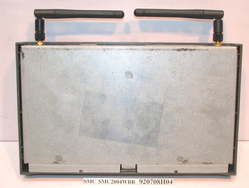
Click to zoom
Application Details
- Equipment Class
- DTS - Digital Transmission System
- Date of Grant
- Aug 06, 2003
- Application Purpose
- Original Equipment
- Date of Application
- Aug 06, 2003
- Equipment Note
- Barricade g 2.4GHz 54 Mbps Wireless Router
- Frequency Range
- 2412.00000000 - 2462.00000000
- Company
- Accton Technology Corp
- Country
- Taiwan
Documents & Files
Document Text
Text extracted from the exhibit documents filed with the FCC. Open a document above to read the original.
Users Manual
38 Tesla Irvine, CA 92618 Phone: (949) 679-8000 Barricade TM g 2.4 GHz 54 Mbps Wireless Cable/DSL Broadband Router From SMC’s Barricade line of Broadband Routers July 2003 Revision Number: V.2 R01 COPYRIGHT Information furnished by SMC Networks, Inc. (SMC) is believed to be accurate and reliable. However, no responsibility is assumed by SMC for its use, nor for any infringements of patents or other rights of third parties which may result from its use. No license is granted by implication or otherwise under any patent or patent rights of SMC. SMC reserves the right to change specifications at any time without notice. Copyright © 2003 by SMC Networks, Inc. 38 Tesla Irvine, CA 92618 All rights reserved. Trademarks: SMC is a registered trademark; and Barricade is a trademark of SMC Networks, Inc. Other product and company names are trademarks or registered trademarks of their respective holders. i COMPLIANCES Federal Communication Commission Interference Statement This equipment has been tested and found to comply with the limits for a Class B digital device, pursuant to Part 15 of the FCC Rules. These limits are designed to provide reasonable protection against harmful interference in a residential installation. This equipment generates, uses and can radiate radio frequency energy and, if not installed and used in accordance with the instructions, may cause harmful interference to radio communications. However, there is no guarantee that interference will not occur in a particular installation. If this equipment does cause harmful interference to radio or television reception, which can be determined by turning the equipment off and on, the user is encouraged to try to correct the interference by one of the following measures: •Reorient or relocate the receiving antenna •Increase the separation between the equipment and receiver •Connect the equipment into an outlet on a circuit different from that to which the receiver is connected •Consult the dealer or an experienced radio/TV technician for help FCC Caution: To assure continued compliance, (example - use only shielded interface cables when connecting to computer or peripheral devices) any changes or modifications not expressly approved by the party responsible for compliance could void the user's authority to operate this equipment. This device complies with Part 15 of the FCC Rules. Operation is subject to the following two conditions: (1) This device may not cause harmful interference, and (2) this device must accept any interference received, including interference that may cause undesired operation. IMPORTANT NOTE: FCC Radiation Exposure Statement This equipment complies with FCC radiation exposure limits set forth for an uncontrolled environment. This equipment should be installed and operated with a minimum distance of 20 centimeters (8 inches) between the radiator and your body. This transmitter must not be co-located or operating in conjunction with any other antenna or transmitter. Compliances ii EC Conformance Declaration - Class B SMC contact for these products in Europe is: SMC Networks Europe, Edificio Conata II, Calle Fructuós Gelabert 6-8, 2 o , 4 a , 08970 - Sant Joan Despí, Barcelona, Spain. This information technology equipment complies with the requirements of the Council Directive 89/336/EEC on the Approximation of the laws of the Member States relating to Electromagnetic Compatibility and 73/23/EEC for electrical equipment used within certain voltage limits and the Amendment Directive 93/68/ EEC. For the evaluation of the compliance with these Directives, the following standards were applied: RFI Emission: * Limit class B according to EN 55022:1998 * Limit class B for harmonic current emission according to EN 61000-3-2/ 1995 * Limitation of voltage fluctuation and flicker in low-voltage supply system according to EN 61000-3-3/1995 Immunity: * Product family standard according to EN 55024:1998 * Electrostatic Discharge according to EN 61000-4-2:1995 (Contact Discharge: ±4 kV, Air Discharge: ±8 kV) * Radio-frequency electromagnetic field according to EN 61000-4-3: 1996 (80 - 1000 MHz with 1 kHz AM 80% Modulation: 3 V/m) * Electrical fast transient/burst according to EN 61000-4-4:1995(AC/DC power supply: ±1 kV, Data/Signal lines: ±0.5 kV) * Surge immunity test according to EN 61000-4-5:1995(AC/DC Line to Line: ±1 kV, AC/DC Line to Earth: ±2 kV) * Immunity to conducted disturbances, Induced by radio-frequency fields: EN 61000-4-6:1996(0.15 - 80 MHz with 1 kHz AM 80% Modulation: 3V/m) * Power frequency magnetic field immunity test according to EN 61000-4-8:1993(1 A/m at frequency 50 Hz) * Voltage dips, short interruptions and voltage variations immunity test according to EN 61000-4-11:1994(>95% Reduction @10 ms, 30% Reduction @500 ms, >95% Reduction @5000 ms) LVD:* EN60950(A1/1992; A2/1993; A3/1993; A4/1995; A11/1997) Compliances iii Industry Canada - Class B This digital apparatus does not exceed the Class B limits for radio noise emissions from digital apparatus as set out in the interference-causing equipment standard entitled “Digital Apparatus,” ICES-003 of the Department of Communications. Cet appareil numérique respecte les limites de bruits radioélectriques applicables aux appareils numériques de Classe B prescrites dans la norme sur le matériel brouilleur: “Appareils Numériques,” NMB-003 édictée par le ministère des Communications. Australia AS/NZS 3548 (1995) - Class B SMC contact for products in Australia is: SMC Communications Pty. Ltd. Suite 18, 12 Tryon Road, Lindfield NSW2070, Phone: 61-2-8875-7887 Fax: 61-2-8875-7777 Safety Compliance Underwriters Laboratories Compliance Statement Important! Before making connections, make sure you have the correct cord set. Check it (read the label on the cable) against the following: The unit automatically matches the connected input voltage. Therefore, no additional adjustments are necessary when connecting it to any input voltage within the range marked on the rear pa…
Text truncated - open the document above for the full version.
Users Manual
Advanced Setup 41 register a new MAC address for your account. Register the default MAC address of the Router. Point-to-Point Over Ethernet (PPPoE) Enter the PPPoE User Name and Password assigned by your Service Provider. The Service Name is normally optional, but may be required by some service providers. The MTU (Maximum Transmission Unit) governs the maximum size of the data packets. Leave this on the default value (1454) unless you have a particular reason to change it. Enter a Maximum Idle Time (in minutes) to define a maximum period of time for which the Internet connection is maintained during inactivity. If the connection is inactive for longer than the Maximum Idle Time, it will be dropped. (Default: 10 minutes) Enable the Auto-reconnect option to automatically re-establish the connection as soon as you attempt to access the Internet again. Configuring the Wireless Barricade g Router 42 Point-to-Point Tunneling Protocol (PPTP) Point-to-Point Tunneling Protocol (PPTP) can be used to join different physical networks using the Internet as an intermediary. Using the above screen allows client PCs to establish a normal PPTP session and provides hassle-free configuration of the PPTP client on each client PC. Enter the assigned IP address, subnet mask and default gateway IP address (usually supplied by your ISP), and then the PPTP User ID, Password and PPPTP Gateway IP address. Enter a maximum Idle Time Out (in minutes) to define a maximum period of time for which the PPTP connection is maintained during inactivity. If the connection is inactive for longer than the Maximum Idle Time, it will be dropped. (Default: 10 minutes) Advanced Setup 43 Static IP Address If your Internet Service Provider has assigned a fixed IP address, enter the assigned address and subnet mask for the Router, then enter the gateway address of your ISP. You may need a fixed address if you want to provide Internet services, such as a web server or FTP server. Configuring the Wireless Barricade g Router 44 BigPond BigPond is a service provider in Australia that uses a heartbeat system to maintain the Internet connection. Configure the built-in client with your user name, password and service name to get online. Leave the Authentication Service Name as “login-server” for a universal configuration. Advanced Setup 45 DNS Domain Name Servers map numerical IP addresses to the equivalent domain name (e.g., www.smc.com). Your ISP should provide the IP address of one or more domain name servers. Enter those addresses in this screen. Configuring the Wireless Barricade g Router 46 LAN •LAN IP – Use the LAN menu to configure the LAN IP address for the Router and to enable the DHCP server for dynamic client address allocation. •Set a period for the lease time if required. For home networks this may be set to Forever, which means there is no time limit on the IP address lease. •IP Address Pool – A dynamic IP address range may be specified (192.168.2.2–254). IP addresses running from 192.168.2.100 to 192.168.2.199 are the default value. Once the IP addresses, e.g. 192.168.2.100–199, have been assigned, these IP addresses will be part of the dynamic IP address pool. IP addresses from 192.168.2.2 to 192.168.2.99, and 192.168.2.200 to 192.168.2.254 will be available as static IP addresses. Remember not to include the address of the Router in the client address pool. Also remember to configure your client PCs for dynamic IP address allocation. Advanced Setup 47 Wireless To configure the Router as a wireless access point for wireless clients (either stationary or roaming), all you need to do is define the radio channel, the Service Set identifier (SSID), and encryption options. Channel and SSID You must specify a common radio channel and SSID (Service Set ID) to be used by the Router and all of your wireless clients. Be sure you configure all of your clients to the same values. ESSID: The Service Set ID. This should be set to the same value as the other wireless devices in your network. Note:The SSID is case sensitive and can consist of up to 32 alphanumeric characters. Configuring the Wireless Barricade g Router 48 Transmission Rate: Set the rate of data transmitted from the Router. The lower the data rate, the longer the transmission distance. (Default: Fully Automatic.) Channel: The radio channel through which the Router communicates with PCs in its BSS. (Default: 6) Note:The available channel settings are limited by local regulations. Broadcast SSID: Broadcasting the SSID on the wireless network for easy connection with client PCs. For security reason, disable SSID broadcast. (Default: Enable) Advanced Setup 49 Encryption If you are transmitting sensitive data across wireless channels, you should enable Wired Equivalent Privacy (WEP) encryption. Encryption requires you to use the same set of encryption/decryption keys for the Router and all of your wireless clients. You can choose between standard 64-bit or the more robust 128-bit encryption. You may manually enter the keys or automatically generate encryption keys. To manually configure the keys, enter five hexadecimal pairs for each 64-bit key, or enter 13 pairs for the single 128-bit key. (A hexadecimal digit is a number or letter in the range 0-9 or A-F.) For automatic 64-bit security, enter a passphrase and click Generate. Four keys will be generated (as shown below). Choose a key from the drop-down list or accept the default key. Automatic 128-bit security generates a single key. Configuring the Wireless Barricade g Router 50 If you use encryption, configure the same keys used for the Router on each of your wireless clients. Note that Wired Equivalent Privacy (WEP) protects data transmitted between wireless nodes, but does not protect any transmissions over your wired network or over the Internet. Advanced Setup 51 NAT - Network Address Translation From this section you can configure the Address Mapping, Virtual Server, and Special Application features that provide control…
Text truncated - open the document above for the full version.
Users Manual
Advanced Setup 61 Intrusion Detection •SPI and Anti-DoS (Denial-of-Service) firewall protection (Default: Disabled) – The Intrusion Detection Feature limits access for incoming traffic at the WAN port. When the SPI (Stateful Packet Inspection) feature is turned on, all incoming packets will be blocked except for those types marked with a check in the Stateful Packet Inspection section. •Discard Ping from WAN (Default: Disabled) – Prevents the router from responding to any PING request on the WAN port. •E-mail Alert Configuration – Enter your E-mail address. Specify your SMTP and POP3 servers, user name, and password. Configuring the Wireless Barricade g Router 62 DMZ (Demilitarized Zone) If you have a client PC that cannot run an Internet application properly from behind the firewall, then you can open the client up to unrestricted two-way Internet access. Enter the IP address of a DMZ host to this screen. Adding a client to the DMZ may expose your local network to a variety of security risks, so only use this option as a last resort. Advanced Setup 63 DDNS (Dynamic DNS) Settings Domain Name – A series of alphanumeric strings separated by periods that maps to the address of a the Router network connection and identifies the owner of the address. Dynamic DNS provides users on the Internet with a method to tie their domain name to the router or server. DDNS allows your domain name to follow your IP address automatically by having your DNS records changed when your IP address changes. The section also has a “Server Configuration” section that automatically opens the port options checked in the Virtual Server section. Simply enter in the IP Address of your server, such as a web server, and then click on the port option “HTTP Port 80” so users can access your server from the WAN connection (Internet). Configuring the Wireless Barricade g Router 64 This DNS feature is powered by TZO.com. With a DDNS connection you can host your own web site, E-mail server, FTP site, and more at your own location even if you have a dynamic IP address. (Default: Disable) UPnP (Universal Plug and Play) Setting Enable UPnP by checking ON in the screen above. UPnP allows the device to automatically: •dynamically join a network •obtain an IP address •convey its capabilities and learn about the presence and capabilities of other devices. Advanced Setup 65 Tools Use the Tools menu to back up the current configuration, restore a previously saved configuration, restore factory settings, update firmware, and reset the Router. Tools - Configuration Tools •Backup – Saves the Router’s configuration to a file. •Restore – Restores settings from a saved backup configuration file. •Restore to factory defaults – Restores the Router settings back to the factory defaults. Configuring the Wireless Barricade g Router 66 Tools - Firmware Upgrade Use this screen to update the firmware or user interface to the latest versions. Download the upgrade file from the SMC web site (www.smc.com) and save it to your hard drive. In the Upgrade Target field, choose Firmware. Then click Browse to look for the previously downloaded file. Click APPLY. Check the Status page Information section to confirm that the upgrade process was successful. Advanced Setup 67 Tools - Reset Click APPLY to reset the Router. The reset will be complete when the power LED stops blinking. Note:If you use the Reset button on the front panel, the Router performs a power reset. If the button is held depressed for over five seconds, all the LEDs will illuminate and the factory settings will be restored. Configuring the Wireless Barricade g Router 68 Status The Status screen displays WAN/LAN connection status, firmware, and hardware version numbers, illegal attempts to access your network, as well as information on DHCP clients connected to your network. The following items are included on this screen: SectionDescription INTERNETDisplays WAN connection type and status. GATEWAYDisplays system IP settings, as well as DHCP and Firewall status. INFORMATIONDisplays the number of attached clients, the firmware versions, the physical MAC address for each media interface, as well as the hardware version and serial number. Security LogDisplays illegal attempts to access your network. SaveClick on this button to save the security log file. ClearClick on this button to delete the access log. RefreshClick on this button to refresh the screen. DHCP Client Log Displays information on all DHCP clients on your network. 69 TROUBLESHOOTING The information outlined in this section describes some useful steps for getting your computer and the Router online. A. Verify your connection to the Router If you are unable to access the Router’s web-based administration pages then you may not be properly connected or configured. The screen shots in this section were taken on a Windows 2000 machine, but the same steps will apply to Windows 95/98/Me/XP. To determine your TCP/IP configuration status please follow the steps below: 1.Click Start then choose Run. 2.Type cmd or command to open a DOS prompt. 3.In the DOS window, type ipconfig and verify the information that is displayed. 4.If your computer is set up for DHCP, then your TCP/IP configuration should be similar to the information displayed: •IP Address: 192.168.2.X (x is number between 100 and 199 by default.) •Subnet: 255.255.255.0 •Gateway: 192.168.2.1 Troubleshooting 70 If you have an IP address that starts with 169.254.XXX.XXX then see the next section. If you have another IP address configured, then see section C. B. I am getting an IP Address that starts with 169.254.XXX.XXX If you are getting this IP Address, then you need to check that you are properly connected to the Router. Confirm that you have a good link light on the Router for the port this computer is connected to. If not, please try another cable. If you have a good link light, please open up a DOS window as described in the previous section and type ipconfig/renew. If you are stil…
Text truncated - open the document above for the full version.
External Photos
Page 1 CONSTRUCTION PHOTOS OF EUT Page 2 Page 3
ID Label/Location Info
(Fig. 1) FCC ID: HED2804WBR FCC LABEL LOCATION The label will be permanently affixed at a conspicuous location on the device. Label
ID Label/Location Info
Tested To Comply With FCC Standards FOR HOME OR OFFICE USE A.C.N. 069 351 613 geprufte Sicherheit .. .. Rheinland Product Safety TUV S RR C US LR99150 4 2 . 0 0 m m 60.00 mm 0560 !
Internal Photos
Page 1 CONSTRUCTION PHOTOS OF EUT Page 2 Page 3 Page 4 Page 5 Page 6 Page 7 Page 8 Page 9 Page 10 Page 11
Operational Description
FCC ID: HED2804WBR Report No.: RF920708H04 ADT No.: 920708H04 Operational Description The transmitter of the EUT (Barricade g 2.4GHz 54Mbps Wireless Cable/DSL Broadband Router) is powered by power adapter. The antenna used in this product is External Dipole antenna with reverse SMA connector. Under normal use condition, the user has to keep at least 20cm separation distance between radiator and the body of the user. The other instruction, please have a look at the users manual. DSSS Information This device is Direct Sequence Spread Spectrum, the data is mixed by pseudorandom code which is an orthogonal code. The mixed data is digital modulated by DBPSK and DQPSK technique depends on the data rates. The CCK coding is applied for increasing the data rate, and also the processing gain will be increased. The bit rates are 1,2,5.5,11Mbps.
RF Exposure Info
FCC ID: HED2804WBR ADT No.: 920708H04 RF EXPOSURE REPORT REPORT NO.: RF920708H04 MODEL NO.: SMC2804WBR, WG4005A 1-17 ACCORDING: FCC Guidelines for Human Exposure IEEE C95.1 APPLICANT: Accton Technology Corporation ADDRESS: No.1, Creation Rd. III, Science-based Industrial Park, Hsinchu, Taiwan, R.O.C. ISSUED BY: Advance Data Technology Corporation LAB LOCATION: No. 81-1, Lu Liao Keng, 9 Ling, Wu Lung Tsuen, Chiung Lin Hsiang, Hsin Chu Hsien, Taiwan, R.O.C. Lab Code: 200376-0 FCC ID: HED2804WBR ADT No.: 920708H04 RF Exposure Measurement 1. Introduction In this document, we try to prove the safety of radiation harmfulness to the human body for our product. The limit for Maximum Permissible Exposure (MPE) specified in FCC 1.1310 is followed. The Gain of the antenna used in this product is measured in a Fully Anechoic Chamber (FAC) calibrated for antenna measurement in ADT, and also the maximum total power input to the antenna is measured. Through the Friis transmission formula and the maximum gain of the antenna, we can calculate the distance, away from the product, where the limit of MPE is reached. Although the Friis transmission formula is a far field assumption, the calculated result of that is an over-prediction for near field power density. We will take that as the worst case to specify the safety range. 2. RF Exposure Limit According to FCC 1.1310: The criteria listed in the following table shall be used to evaluate the environmental impact of human exposure to radio-frequency (RF) radiation as specified in 1.1307(b) LIMITS FOR MAXIMUM PERMISSIBLE EXPOSURE (MPE) Frequency Range (MHz) Electric Field Strength (V/m) Magnetic Field Strength (A/m) Power Density (mW/cm 2 ) Average Time (minutes) (A)Limits For Occupational / Control Exposures 300-1500......F/3006 1500-100,000......56 (B)Limits For General Population / Uncontrolled Exposure 300-1500......F/15006 1500-100,000......1.030 F = Frequency in MHz FCC ID: HED2804WBR ADT No.: 920708H04 3. Friis Formula Friis transmission formula : Pd = (Pout*G) / (4*pi*r 2 ) where Pd = power density in mW/cm 2 Pout = output power to antenna in mW G = gain of antenna in linear scale Pi = 3.1416 R = distance between observation point and center of the radiator in cm Pd is the limit of MPE, 1 mW/cm 2 . If we know the maximum Gain of the antenna and the total power input to the antenna, through the calculation, we will know the MPE value at distance 20cm. Ref. : David K. Cheng, Field and Wave Electromagnetics, Second Edition, Page 640, Eq. (11-133). 4 EUT Operating condition The software provided by Manufacturer enabled the EUT to transmit and receive data at lowest, middle and highest channel individually. 5. Classification This device is not fixed inside the host equipment, it is connected with host through wire. So it is easy to be re-located in the place where at least 20 cm far away from the body of the user. Warning statement to the user for keeping at least 20cm or more separation distance with the antenna should be included in users manual. So, this device is classified as Mobile Device. FCC ID: HED2804WBR ADT No.: 920708H04 6 Test Results 6.1 Antenna Gain The maximum Gain measured in Fully Anechoic Chamber is 1.5dBi or 1.41 (numeric). 6.2 Output Power Into Antenna & RF Exposure value at distance 20cm: (For DSSS) Channel Channel Frequency (MHz) Output Power to Antenna (mW) Power Density (mW/cm 2 ) Limit of Power Density (mW/cm 2 ) 1241263.5330.01785371.0 6243765.6150.01843871.0 11246267.6080.01899891.0 (For OFDM) Channel Channel Frequency (MHz) Output Power to Antenna (mW) Power Density (mW/cm 2 ) Limit of Power Density (mW/cm 2 ) 1241216.2550.0045681.0 6243716.7110.0046961.0 11246217.1400.0048161.0
Test Report
FCC ID: HED2804WBR Report No.: RF920708H041Issued: Jul.31, 2003 ADT No.: 920708H04 FCC TEST REPORT REPORT NO.: RF920708H04 MODEL NO.: SMC2804WBR, WG4005A 1-17 RECEIVED: Jul. 08, 2003 TESTED: Jul. 09 to 19, 2003 APPLICANT: Accton Technology Corporation ADDRESS: No.1, Creation Rd. III, Science-based Industrial Park, Hsinchu, Taiwan, R.O.C. ISSUED BY: Advance Data Technology Corporation LAB LOCATION: No. 81-1, Lu Liao Keng, 9 Ling, Wu Lung Tsuen, Chiung Lin Hsiang, Hsin Chu Hsien, Taiwan, R.O.C. This test report consists of 60 pages in total. It may be duplicated completely for legal use with the approval of the applicant. It should not be reproduced except in full, without the written approval of our laboratory. The client should not use it to claim product endorsement by NVLAP or any government agencies. The test results in the report only apply to the tested sample. Lab Code: 200376-0 FCC ID: HED2804WBR Report No.: RF920708H042Issued: Jul.31, 2003 ADT No.: 920708H04 Table of Contents 1CERTIFICATION.......................................................................................................4 2SUMMARY OF TEST RESULTS............................................................................5 3GENERAL INFORMATION.....................................................................................6 3.1GENERAL DESCRIPTION OF EUT......................................................................6 3.2DESCRIPTION OF TEST MODES........................................................................8 3.3GENERAL DESCRIPTION OF APPLIED STANDARDS...................................8 3.4DESCRIPTION OF SUPPORT UNITS..................................................................9 4TEST TYPES AND RESULTS..............................................................................11 4.1CONDUCTED EMISSION MEASUREMENT.....................................................11 4.1.1LIMITS OF CONDUCTED EMISSION MEASUREMENT................................11 4.1.2TEST INSTRUMENTS...........................................................................................11 4.1.3TEST SETUP..........................................................................................................12 4.1.4EUT OPERATING CONDITIONS........................................................................13 4.1.5TEST RESULTS......................................................................................................14 4.2Radiated Emission Measurement........................................................................16 4.2.1LIMITS OF RADIATED EMISSION MEASUREMENT......................................16 4.2.2TEST INSTRUMENTS...........................................................................................17 4.2.3TEST PROCEDURES...........................................................................................18 4.2.4TEST SETUP..........................................................................................................19 4.2.5EUT OPERATING CONDITIONS........................................................................19 4.2.6TEST RESULTS......................................................................................................20 4.2.7TEST RESULTS – DSSS......................................................................................21 4.2.8TEST RESULTS –OFDM......................................................................................24 4.36dB BANDWIDTH MEASUREMENT..................................................................27 4.3.1LIMITS OF 6dB BANDWIDTH MEASUREMENT..............................................27 4.3.2TEST INSTRUMENTS...........................................................................................27 4.3.3TEST PROCEDURE..............................................................................................28 4.3.4TEST SETUP..........................................................................................................28 4.3.5EUT OPERATING CONDITIONS........................................................................28 4.3.6TEST RESULTS-DSSS.........................................................................................29 4.3.7TEST RESULTS-OFDM........................................................................................33 4.4MAXIMUM PEAK OUTPUT POWER..................................................................37 4.4.1LIMITS OF MAXIMUM PEAK OUTPUT POWER MEASUREMENT.............37 FCC ID: HED2804WBR Report No.: RF920708H043Issued: Jul.31, 2003 ADT No.: 920708H04 4.4.2TEST INSTRUMENTS...........................................................................................37 4.5MAXIMUM PEAK OUTPUT POWER..................................................................37 4.5.1LIMITS OF MAXIMUM PEAK OUTPUT POWER MEASUREMENT.............37 4.5.2TEST INSTRUMENTS...........................................................................................37 4.5.3TEST PROCEDURES...........................................................................................38 4.5.4TEST SETUP..........................................................................................................38 4.5.5EUT OPERATING CONDITIONS........................................................................38 4.5.6TEST RESULTS-DSSS.........................................................................................39 4.5.7TEST RESULTS-OFDM........................................................................................39 4.6POWER SPECTRAL DENSITY MEASUREMENT...........................................40 4.6.1LIMITS OF POWER SPECTRAL DENSITY MEASUREMENT.......................40 4.6.2TEST INSTRUMENTS...........................................................................................40 4.6.3TEST PROCEDURE..............................................................................................41 4.6.4TEST SETUP.....................................................................…
Text truncated - open the document above for the full version.
Test Report
FCC ID: HED2804WBR Report No.: RF920708H0431Issued: Jul.31, 2003 ADT No.: 920708H04 CH6 FCC ID: HED2804WBR Report No.: RF920708H0432Issued: Jul.31, 2003 ADT No.: 920708H04 CH11 FCC ID: HED2804WBR Report No.: RF920708H0433Issued: Jul.31, 2003 ADT No.: 920708H04 4.3.7 TEST RESULTS-OFDM EUT Barricade g 2.4GHz 54Mbps Wireless Cable/DSL Broadband Router INPUT POWER (SYSTEM) 120Vac, 60 Hz ENVIRONMENTAL CONDITIONS 26 deg. C, 58 %RH, 965 hPa MODELSMC2804WBR TESTED BY Eric Lee CHANNEL CHANNEL FREQUENCY (MHz) 6 dB BANDWIDTH (MHz) MINIMUM LIMIT (MHz) PASS/FAIL 1241216.360.5PASS 6243716.360.5PASS 11246216.400.5PASS FCC ID: HED2804WBR Report No.: RF920708H0434Issued: Jul.31, 2003 ADT No.: 920708H04 CH1 FCC ID: HED2804WBR Report No.: RF920708H0435Issued: Jul.31, 2003 ADT No.: 920708H04 CH6 FCC ID: HED2804WBR Report No.: RF920708H0436Issued: Jul.31, 2003 ADT No.: 920708H04 CH11 FCC ID: HED2804WBR Report No.: RF920708H0437Issued: Jul.31, 2003 ADT No.: 920708H04 4.4 MAXIMUM PEAK OUTPUT P…
Text truncated - open the document above for the full version.
Contact Information
Applicant
Abby Wei(Manager)
Technical Contact
Advance Data Technology Corp.Eric Lin
[email protected]+886-3-593-5343
81-1 Luliaoken 9th Lin, Wulung Tsuen · Hsinchu · Taiwan
Test Firm
Bureau Veritas CPS (H.K.) Ltd. Taoyuan BranchRichard Chen
Technical Specifications
| # | Rule Parts | Frequency Range | Power Output |
|---|---|---|---|
| 1 | 15C | 2.41 GHz - 2.46 GHz | 68.00 mW |
Other Applications from Accton Technology Corp

HEDEAP115
Jan 27, 2026Wi-Fi 7 AP
Equipment Class
NII - Unlicensed National Information Infrastructure TX
HEDEAP112
Oct 13, 2024Wi-Fi 6 IoT Gateway
Equipment Class
DTS - Digital Transmission System
HEDEAP111
Mar 17, 2024Wi-Fi 6 Access Point
Equipment Class
DTS - Digital Transmission System
HEDOAP101E
Oct 24, 2023Outdoor Access Point
Equipment Class
DTS - Digital Transmission System
HEDEAP104
Dec 14, 2022Indoor Wall Plate WiFi 6 Access Point
Equipment Class
DTS - Digital Transmission System