HED3CRSHPW796Wireless LAN Cardbus
Accton Technology Corp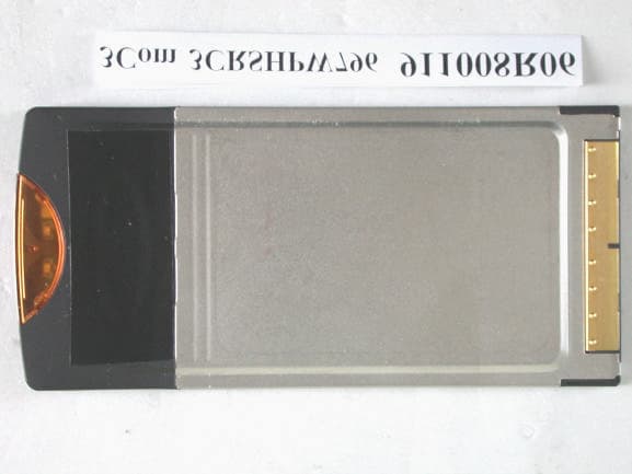
Click to zoom
Application Details
- Equipment Class
- DTS - Digital Transmission System
- Date of Grant
- Nov 05, 2002
- Application Purpose
- Original Equipment
- Date of Application
- Nov 05, 2002
- Equipment Note
- Wireless LAN Cardbus
- Frequency Range
- 2412.00000000 - 2462.00000000
- Company
- Accton Technology Corp
- Country
- Taiwan
Documents & Files
Document Text
Text extracted from the exhibit documents filed with the FCC. Open a document above to read the original.
Users Manual
Wireless LAN PC Card User Guide 3CRSHPW796 Wireless LAN PC Card http://www.3com.com/ Published September 2002 DUA0079-6AAA02 3Com Corporation 5400 Bayfront Plaza Santa Clara, California 95052-8145 Copyright © 2002, 3Com Technologies. All rights reserved. No part of this documentation may be reproduced in any form or by any means or used to make any derivative work (such as translation, transformation, or adaptation) without written permission from 3Com Technologies. 3Com Technologies reserves the right to revise this documentation and to make changes in content from time to time without obligation on the part of 3Com Technologies to provide notification of such revision or change. 3Com Technologies provides this documentation without warranty, term, or condition of any kind, either implied or expressed, including, but not limited to, the implied warranties, terms or conditions of merchantability, satisfactory quality, and fitness for a particular purpose. 3Com may make improvements or changes in the product(s) and/or the program(s) described in this documentation at any time. If there is any software on removable media described in this documentation, it is furnished under a license agreement included with the product as a separate document, in the hard copy documentation, or on the removable media in a directory file named LICENSE.TXT or !LICENSE.TXT. If you are unable to locate a copy, please contact 3Com and a copy will be provided to you. UNITED STATES GOVERNMENT LEGEND If you are a United States government agency, then this documentation and the software described herein are provided to you subject to the following: All technical data and computer software are commercial in nature and developed solely at private expense. Software is delivered as “Commercial Computer Software” as defined in DFARS 252.227-7014 (June 1995) or as a “commercial item” as defined in FAR 2.101(a) and as such is provided with only such rights as are provided in 3Com’s standard commercial license for the Software. Technical data is provided with limited rights only as provided in DFAR 252.227-7015 (Nov 1995) or FAR 52.227-14 (June 1987), whichever is applicable. You agree not to remove or deface any portion of any legend provided on any licensed program or documentation contained in, or delivered to you in conjunction with, this User Guide. Unless otherwise indicated, 3Com registered trademarks are registered in the United States and may or may not be registered in other countries. 3Com and the 3Com logo are registered trademarks of 3Com Corporation. IEEE and 802 are registered trademarks of the Institute of Electrical and Electronics Engineers, Inc. Intel and Pentium are registered trademarks of Intel Corporation. Microsoft, MS-DOS, Windows, and Windows NT are registered trademarks of Microsoft Corporation. Novell and NetWare are registered trademarks of Novell, Inc. UNIX is a registered trademark in the United States and other countries, licensed exclusively through X/Open Company, Ltd. Netscape Navigator is a registered trademark of Netscape Communications. JavaScript is a trademark of Sun Microsystems. All other company and product names may be trademarks of the respective companies with which they are associated. ENVIRONMENTAL STATEMENT It is the policy of 3Com Corporation to be environmentally-friendly in all operations. To uphold our policy, we are committed to: Establishing environmental performance standards that comply with national legislation and regulations. Conserving energy, materials and natural resources in all operations. Reducing the waste generated by all operations. Ensuring that all waste conforms to recognized environmental standards. Maximizing the recyclable and reusable content of all products. Ensuring that all products can be recycled, reused and disposed of safely. Ensuring that all products are labelled according to recognized environmental standards. Improving our environmental record on a continual basis. End of Life Statement 3Com processes allow for the recovery, reclamation and safe disposal of all end-of-life electronic components. Regulated Materials Statement 3Com products do not contain any hazardous or ozone-depleting material. Environmental Statement about the Documentation The documentation for this product is printed on paper that comes from sustainable, managed forests; it is fully biodegradable and recyclable, and is completely chlorine-free. The varnish is environmentally-friendly, and the inks are vegetable-based with a low heavy-metal content. Contents 1Installing Your Wireless LAN PC Card and 3Com Wireless Card Manager 5 Installation CD5 Windows XP, 2000, Me, and 98 SE5 Confirming Device Installation6 Installing 3Com Wireless Card Manager6 Using Wireless Card Manager6 Wireless LAN PC Card LED Indicators 6 2Troubleshooting7 Diagnosing Problems7 Uninstalling the PC Card7 Uninstalling Wireless Card Manager8 Updating the Wireless LAN PC Card Driver 9 Windows XP and 20009 Windows Me and 98 SE9 ATechnical Support11 Online Technical Services 11 World Wide Web Site11 3Com Knowledgebase Web Services11 3Com FTP Site11 Support from Your Network Supplier12 Support from 3Com12 Returning Products for Repair12 Regulatory Compliance Information13 FCC Part 15 Notice (Applicable to use within the USA)13 Unintentional Radiator 13 Manufacturer’s Declaration of Conformity14 Industry Canada Notice (Applicable for use within Canada)14 Avis de conformité à la réglementation d’Industrie Canada14 Industry Canada (IC) Emissions Compliance Statement 14 Avis de conformité à la réglementation d’Industrie Canada14 Safety Notice14 European Community CE Notice15 Contents 5 1 Installing Your Wireless LAN PC Card and 3Com Wireless Card Manager Installation CD The Installation CD contains: ■Setup programs and drivers for Windows XP, 2000, Millennium Edition (Windows Me), and 98 Second Edition (SE). ■3Com Wireless Card Manager ■Warranty Information ■This Wireless LAN PC Card User Guide ■Wireless L…
Text truncated - open the document above for the full version.
Cover Letter(s)
American Telecommunications Certification Body Inc. 6731 Whittier Ave, McLean, VA 22101 November 6, 2002 RE: Accton Technology Corporation FCC ID: HED3CRSHPW796 After a review of the submitted information, I have a few comments on the above referenced Application. 1) The block diagram should show the frequencies of all oscillators in the device (CFR 2.1033(a)(5)) not just the transmit channels. Please provide an updated version that includes this information. 2) Please explain the purpose of the copper tape to the external part of the unit. How will this be implemented into production models. 3) The operational description/RF exposure/Users Manual exhibits explain that the device is to be used with 2.5 cm spacing. The device may be used as a general purpose PCMCIA card in a variety of devices including laptops & PDA's, etc. (some of these devices may be used in the lap or while on the body). Therefore touch position IS considered applicable and the device must be subject to portable exposure conditions (2.5 cm separation distance is NOT considered applicable). Please provide a corrected operational description. 4) Please remove the phrase " In order to comply with FCC radio-frequency radiation exposure compliance requirements, a separation distance of at least 2.5 cm (1.0 inch) must be maintained between the antenna of the device and all persons." from the users manual since it is not considered applicable. 5) The operational description mentions a modular approval and mobile applications specific to access points, etc. Please explain. 6) Maximum power is not listed correctly on page 6 of the test report. This should be 12.70 dBm. Please correct. 7) Section 4.6.6 is not calculated for the worse case margin on the low side of the bandedge. Please add these calculations to the report. 8) The gain specified in the test report section 4.7 is 0.8 dBi, while the RF exposure lists 0.0 dBi. Which is correct? Please correct the affected exhibits. Timothy R. Johnson Examining Engineer mailto: [email protected] The items indicated above must be submitted before processing can continue on the above referenced application. Failure to provide the requested information may result in application termination. Correspondence should be considered part of the permanent submission and may be viewed from the Internet after a Grant of Equipment Authorization is issued. Please do not respond to this correspondence using the email reply button. In order for your response to be processed expeditiously, you must submit your documents through the AmericanTCB.com website. Also, please note that partial responses increase processing time and should not be submitted. Any questions about the content of this correspondence should be directed to the sender.
Cover Letter(s)
Dear Tim, FCC ID: HED3CRSHPW796 I will re-submit the revised vision of RF exposure, FCC test report and Operation Description as soon as possible. And for explain, the question that u pointed out about the purpose of copper tape: Explaination: The copper tape is used for the countermeasure of EMI, it will be implement into the inner side of the product to enhance the grouding. Best Regards, Kelsey Subject: Reply the question for the FCC ID: HED3CRSHPW796 To: [email protected] Cc: [email protected], [email protected] 11/7/2002file://C:\DOCUME~1\TIMOTH~1.JOH\LOCALS~1\Temp\eud198.htm
External Photos
Page 1 ANNEX PHOTOGRAPHS OF EUT Page 2 Page 3
ID Label/Location Info
LABEL LOCATION FOR FCC ID
ID Label/Location Info
91 10 31 Sylin 146000023300E WN3304A-32 White Mylar + PP UL approve R01 UL Label Black MM +/-0.2MM 0.072MM 62.50 3 9 . 0 0 1 3 . 5 0 44.50 R4 x 4 Note: About the zone on oblique line: 1. Don't with PP 2. Don't need to show up any line IC:XXXXXXXXXXXXXX FCC ID:HED3CRSHPW796 Made in XXXXXX XX 146000023300E R01 XX
Internal Photos
Page 4 Page 5 Page 6 Page 7 Page 8 Page 9
Operational Description
FCC ID: HED3CRSHPW796 ADT No.911008R06 Operational Description The transmitter of the EUT (OfficeConnect ® 11Mbps Wireless LAN Cardbus PC Card) is powered by host equipment. The antenna is Printed antenna without connector. The other instruction, please have a look at the users manual. DSSS Information This device is Direct Sequence Spread Spectrum, the data is mixed by pseudorandom code which is an orthogonal code. The mixed data is digital modulated by BPSK and QPSK technique depends on the data rates. The CCK coding is applied for increasing the data rate, and also the processing gain will be increased. The bit rates are 1,2,5.5,11Mbps, the symbol rates are 1,1,1.375,1.375Mbps, the chip rates are always 11Mbps. So, the Chip/symbol is 11,11,8 and 8 respectively. Although is higher bit rate, the processing gain is lower than 10, but the CCK coding used in higher bit rate will provide 2.2dB coding gain.
RF Exposure Info
FCC ID: HED3CRSHPW796 ADT No.: 911008R06 FCC TEST REPORT REPORT NO.: RF911008R06 MODEL NO.: 3CRSHPW796 ACCORDING: FCC Guidelines for Human Exposure IEEE C95.1 APPLICANT:ACCTON TECHNOLOGY CORPORATION ADDRESS: No.1, Creation Rd., III, Science-Based Industrial Park, Hsinchu, Taiwan, R.O.C. ISSUED BY:Advance Data Technology Corporation LAB LOCATION:47 14th Lin, Chiapau Tsun, Linko, Taipei, Taiwan, R.O.C. 0528 ILAC MRA Lab Code: 200102-0 FCC ID: HED3CRSHPW796 ADT No.: 911008R06 RF Exposure Measurement (Portable Device) 1. Introduction 2.4 GHz frequency band is regarded specially as a dangerous band for its heating harmfulness to the human body. That’s why microwave oven is operating in this frequency band. The manufacturer whose product is working in this frequency band is obligatory to prove the harmfulness of his product. In this document, we try to prove the safety of radiation harmfulness to the human body for our product. The limit for Maximum Permissible Exposure (MPE) specified in FCC 1.1310 is followed. The Gain of the antenna used in this product is measured in a Fully Anechoic Chamber (FAC), and the maximum total power input to the antenna is measured. Through the Friis transmission formula and the maximum gain of the antenna, we can calculate the distance, away from the product, where the limit of MPE is reached. 2. RF Exposure Limit According to FCC 1.1310: The criteria listed in the following table shall be used to evaluate the environmental impact of human exposure to radio-frequency (RF) radiation as specified in 1.1307(b). FCC ID: HED3CRSHPW796 ADT No.: 911008R06 LIMITS FOR MAXIMUM PERMISSIBLE EXPOSURE (MPE) Frequency Range (MHz) Electric Field Strength (V/m) Magnetic Field Strength (A/m) Power Density (mW/cm 2 ) Average Time (minutes) (A)Limits For Occupational / Control Exposures 30-30061.40.1631.06 300-1500......F/3006 1500-100,000......56 (B)Limits For General Population / Uncontrolled Exposure 30-30027.50.0730.230 300-1500......F/150030 1500-100,000......1.030 F = Frequency in MHz 3. Friis Formula Friis transmission formula : Pd = (Pout*G) / (4*pi*r 2 ) where Pd = power density in mW/cm 2 Pout = output power to antenna in mW G = gain of antenna in linear scale Pi = 3.1416 R = distance between observation point and center of the radiator in cm Pd is the limit of MPE, 1 mW/cm 2 . If we know the maximum Gain of the antenna and the total power input to the antenna, through the calculation, we will know the distance r where the MPE limit is reached. Ref. : David K. Cheng, Field and Wave Electromagnetics, Second Edition, Page 640, Eq. (11-133). 4. EUT Operating condition The software provided by Manufacturer enabled the EUT to transmit and receive data at lowest, middle and highest channel individually. FCC ID: HED3CRSHPW796 ADT No.: 911008R06 5. Test Results 5.1 Antenna Gain The maximum Gain measured in Fully Anechoic Chamber is 0.8 dBi or 1 (numeric). 5.2 Output Power Into Antenna & RF Exposure Distance : CHANNEL CHANNEL FREQUENCY (MHz) OUTPUT POWER TO ANTENNA (mW) MINIMUM ALLOWABLE DISTANCE ( r ) FROM SKIN (Centi-Meter) 1241217.381.29 6243718.371.33 11246218.621.33 The minimum allowable distance is very close to the enclosure of the antenna and is very far away from the human being under normal use condition.
Test Report
FCC ID: HED3CRSHPW796 Report No.: RF911008R061Issued: Oct. 31, 2002 FCC TEST REPORT REPORT NO.: RF911008R06 MODEL NO.: 3CRSHPW796 RECEIVED: Oct. 08, 2002 TESTED: Oct. 22~ Oct. 23, 2002 APPLICANT:ACCTON TECHNOLOGY CORPORATION ADDRESS:No. 1, Creation Rd., III, Science-Based Industrial Park, Hsinchu, Taiwan, R.O.C. ISSUED BY:Advance Data Technology Corporation LAB LOCATION: 47 14th Lin, Chiapau Tsun, Linko, Taipei, Taiwan, R.O.C. This test report consists of 49 pages in total. It may be duplicated completely for legal use with the approval of the applicant. It should not be reproduced except in full, without the written approval of our laboratory. The client should not use it to claim product endorsement by CNLA, NVLAP or any government agencies. The test results in the report only apply to the tested sample. 0528 ILAC MRA Lab Code: 200102-0 FCC ID: HED3CRSHPW796 Report No.: RF911008R062Issued: Oct. 31, 2002 Table of Contents 1CERTIFICATION............................................................................................4 2SUMMARY OF TEST RESULTS...................................................................5 3GENERAL INFORMATION............................................................................6 3.1GENERAL DESCRIPTION OF EUT..............................................................6 3.2DESCRIPTION OF TEST MODES................................................................7 3.3GENERAL DESCRIPTION OF APPLIED STANDARDS................................7 3.4DESCRIPTION OF SUPPORT UNITS...........................................................8 4TEST TYPES AND RESULTS.......................................................................9 4.1CONDUCTED EMISSION MEASUREMENT.................................................9 4.1.1LIMITS OF CONDUCTED EMISSION MEASUREMENT..............................9 4.1.2TEST INSTRUMENTS...................................................................................9 4.1.3TEST PROCEDURES..................................................................................10 4.1.4DEVIATION FROM TEST STANDARD........................................................10 4.1.5TEST SETUP...............................................................................................11 4.1.6EUT OPERATING CONDITIONS.................................................................12 4.1.7TEST RESULTS...........................................................................................13 4.2RADIATED EMISSION MEASUREMENT....................................................19 4.2.1LIMITS OF RADIATED EMISSION MEASUREMENT.................................19 4.2.2TEST INSTRUMENTS.................................................................................20 4.2.3TEST PROCEDURES..................................................................................21 4.2.4DEVIATION FROM TEST STANDARD........................................................21 4.2.5TEST SETUP...............................................................................................22 4.2.6EUT OPERATING CONDITIONS.................................................................22 4.2.7TEST RESULTS...........................................................................................23 4.36dB BANDWIDTH MEASUREMENT...........................................................27 4.3.1LIMITS OF 6dB BANDWIDTH MEASUREMENT.........................................27 4.3.2TEST INSTRUMENTS.................................................................................27 4.3.3TEST PROCEDURE....................................................................................28 4.3.4DEVIATION FROM TEST STANDARD........................................................28 4.3.5TEST SETUP...............................................................................................28 4.3.6EUT OPERATING CONDITIONS.................................................................28 4.3.7TEST RESULTS...........................................................................................29 4.4MAXIMUM PEAK OUTPUT POWER...........................................................33 4.4.1LIMITS OF MAXIMUM PEAK OUTPUT POWER MEASUREMENT............33 4.4.2TEST INSTRUMENTS.................................................................................33 FCC ID: HED3CRSHPW796 Report No.: RF911008R063Issued: Oct. 31, 2002 4.4.3TEST PROCEDURES..................................................................................34 4.4.4DEVIATION FROM TEST STANDARD........................................................34 4.4.5TEST SETUP...............................................................................................34 4.4.6EUT OPERATING CONDITIONS.................................................................34 4.4.7TEST RESULTS...........................................................................................35 4.5POWER SPECTRAL DENSITY MEASUREMENT......................................36 4.5.1LIMITS OF POWER SPECTRAL DENSITY MEASUREMENT....................36 4.5.2TEST INSTRUMENTS.................................................................................36 4.5.3TEST PROCEDURE....................................................................................37 4.5.4DEVIATION FROM TEST STANDARD........................................................37 4.5.5TEST SETUP...............................................................................................37 4.5.6EUT OPERATING CONDITIONS.................................................................37 4.5.7TEST RESULTS...........................................................................................38 4.6BAND EDGES MEASUREMENT.................................................................42 4.6.1LIMITS OF BAND EDGES MEASUREMENT..............................................42 4.6.2TEST INSTRUMENTS.................................................................................42 4.6.3TEST PROCEDURE..............…
Text truncated - open the document above for the full version.
Test Setup Photos
FCC ID: HED3CRSHPW796 Report No.: RF911008R0647Issued: Oct. 31, 2002 5 PHOTOGRAPHS OF THE TEST CONFIGURATION CONDUCTED EMISSION TEST FCC ID: HED3CRSHPW796 Report No.: RF911008R0648Issued: Oct. 31, 2002 RADIATED EMISSION TEST
Contact Information
Applicant
Abby Wei(Manager)
Technical Contact
Advance Data Technology CorporationVivi Wang
[email protected]+886-3-327-0910
13-1, Lane 19, WenShan 3rd., St. · Taoyuan · Taiwan
Non-Technical Contact
Advance Data Technology CorporationVivi Wang
[email protected]+886-3-327-0910
Test Firm
Bureau Veritas CPS (H.K.) Ltd. Taoyuan BranchTommy Wu
Technical Specifications
| # | Rule Parts | Frequency Range | Power Output |
|---|---|---|---|
| 1 | 15C | 2.41 GHz - 2.46 GHz | 18.60 mW |
Other Applications from Accton Technology Corp

HEDEAP115
Jan 27, 2026Wi-Fi 7 AP
Equipment Class
NII - Unlicensed National Information Infrastructure TX
HEDEAP112
Oct 13, 2024Wi-Fi 6 IoT Gateway
Equipment Class
DTS - Digital Transmission System
HEDEAP111
Mar 17, 2024Wi-Fi 6 Access Point
Equipment Class
DTS - Digital Transmission System
HEDOAP101E
Oct 24, 2023Outdoor Access Point
Equipment Class
DTS - Digital Transmission System
HEDEAP104
Dec 14, 2022Indoor Wall Plate WiFi 6 Access Point
Equipment Class
DTS - Digital Transmission System