HEDACCWA5001Wireless LAN Access Point
Accton Technology Corp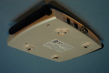
Click to zoom
Application Details
- Equipment Class
- NII - Unlicensed National Information Infrastructure TX
- Date of Grant
- Nov 06, 2001
- Application Purpose
- Original Equipment
- Date of Application
- Nov 06, 2001
- Equipment Note
- Wireless LAN Access Point
- Frequency Range
- 5250.00000000 - 5350.00000000
- Company
- Accton Technology Corp
- Country
- Taiwan
Documents & Files
Document Text
Text extracted from the exhibit documents filed with the FCC. Open a document above to read the original.
Users Manual
AP User’s Guide • Page 1 Subject to change without notice. October 2001 FCCID: HEDACCWA5001 ACCTON TECHNOLOGY CORPORATION WA5001 ACCESS POINT User’s Guide Release 1.0 D O N O T C O P Y Preliminary Page 2 • AP User’s Guide Confidential and Proprietary October 2001 Subject to change without notice. © 2000–2001 by Accton Technology Corp. All rights reserved. Notice The information in this document has been carefully reviewed and is believed to be accurate. Nonetheless, this document is subject to change without notice, and Accton Technology Corp. assumes no responsibility for any inaccuracies that may be contained in this document, and makes no commitment to update or to keep current the contained information, or to notify a person or organization of any updates. Accton reserves the right to make changes, at any time, in order to improve reliability, function or design and to attempt to supply the best product possible. Accton does not represent that products described herein are free from patent infringement or from any other third party right. No part of this document may be reproduced, adapted or transmitted in any form or by any means, electronic or mechanical, for any purpose, except as expressly set forth in a written agreement signed by Accton. Accton or its affiliates may have patents or pending patent applications, trademarks, copyrights, maskwork rights or other intellectual property rights that apply to the ideas, material and information expressed herein. No license to such rights is provided except as expressly set forth in a written agreement signed by Accton. D O N O T C O P Y Preliminary AP User’s Guide • Page 3 Subject to change without notice. October 2001 Table of Contents 1 INTRODUCTION.....................................................................................................4 1.1 PACKAGE CONTENTS............................................................................................4 1.2 SYSTEM REQUIREMENTS.......................................................................................4 2 GETTING TO KNOW THE ACCTON ACCESS POINT....................................5 2.1 FRONT VIEW.........................................................................................................5 2.2 REAR VIEW...........................................................................................................6 2.3 AP NETWORK ATTACHMENT AND CONFIGURATION.............................................8 2.3.1 Booting VxWorks From the Ethernet Connection to the HPC..................13 2.3.2 Booting VxWorks From Flash Memory.....................................................15 2.4 CONFIGURING THE AP........................................................................................16 2.4.1 Web Browser..............................................................................................16 2.4.2 Command-Line Interface...........................................................................19 2.5 REGULATORY COMPLIANCE INFORMATION........................................................22 D O N O T C O P Y Preliminary Page 4 • AP User’s Guide Confidential and Proprietary October 2001 Subject to change without notice. 1 Introduction 1.1 Package Contents The WA5001 Access Point (AP) is provided in a completely enclosed plastic housing with two 180° swivel antennas, a power supply, and a serial cable for use in AP software configuration. The AP contains a single 10/100 Ethernet port. Using this Ethernet port, a RJ-45 cable, (not provided) should be used to connect the AP to a wired Ethernet LAN. 1.2 System Requirements The AP uses the WindRiver Systems VxWorks real-time operating environment, Version 5.4. VxWorks documentation can be obtained through a license agreement with WindRiver Systems. See www.wrs.com for more information about VxWorks licensing. The AP contains a small boot executive that allows the main VxWorks system software to be downloaded using the Ethernet port over an FTP connection. The VxWorks system software can also reside in the Flash memory of the AP, which allows booting without the need to download VxWorks from the host PC over an FTP connection. A configuration file is created in Flash memory to store user configurable parameters such as WEP keys. A terminal or PC with a serial interface and an Ethernet connection is required to perform the initial VxWorks system software loading operation as well as AP configuration. A freeware FTP server (“a-ftp.exe”) is included on the Accton distribution CD in the \utils directory. D O N O T C O P Y Preliminary AP User’s Guide • Page 5 Subject to change without notice. October 2001 2 Getting to Know the Access Point 2.1 Front View The Accton Reference Design Access Point (AP) has 3 LEDs, and a pair of side-mounted antennas that rotate 180° for alternative reception positioning and compact packaging. Table 1 – LED Functionality LED 1 Description Off No Power On Power On and Ready for Operation Blink Power On but Not Ready for Operation – at initial power on or reset, this indicates self-test or software loading; at other times, this indicates a system fault LED 1 (Power Status) LED 2 (Ethernet Link) LED 3 (Wireless Link) Fold this way for storage and packaging Fold this way for wall mount D O N O T C O P Y Preliminary Page 6 • AP User’s Guide Confidential and Proprietary October 2001 Subject to change without notice. LED 2 Description Off No Ethernet Link Detected Green On 100 Mbps Link Detected but No Activity Green Blink 100 Mbps Link Activity – blink rate is proportional to activity Amber On 10 Mbps Link Detected but No Activity Amber Blink 10 Mbps Link Activity – blink rate is proportional to activity LED 3 Description Off Wireless Link Disabled Very Slow Blink Looking for Network Association Slow Blink Associated with Network but No Activity Fast Blink Associated with Network – blink rate is proportional to activity 2.2 Rear View The rear panel of the AP has a RS-232 serial interface, a R…
Text truncated - open the document above for the full version.
Cover Letter(s)
File: R45153 October 19, 2001 Anne Violette ATCB 6731 Whittier Ave Suite C110 McLean, Va. 22101 Dear Anne: The enclosed documents constitute a formal submittal and application for a Grant of Equipment Authorization pursuant to Subpart E of Part 15 of FCC Rules (CFR 47) regarding intentional radiators. Data within this report demonstrates that the equipment tested complies with the FCC limits for intentional radiators. Elliott Laboratories, as duly authorized agent prepared this submittal. A copy of the letter of our appointment as agent is enclosed. If there are any questions or if further information is needed, please contact Elliott Laboratories for assistance. Sincerely, Mark Briggs Director of Engineering MB/dmg Enclosures: Agent Authorization Letter Emissions Test Report with Exhibits
Cover Letter(s)
Accton Technology Corporation No.1 Creation Rd. III, Science – based Industrial Park, Hsin Chu300, Taiwan, R.O.C. Tel:886-5770270 Fax:886-3-5783839 American Telecommunications Certification Body, Inc. 6731 Whittier Avenue Suite C110 McLean, VA 22101 Oct. 23, 2001 To Whom It May Concern: Please be advised that Accton Technology Corporation authorizes Elliott Laboratories to act on our behalf, until otherwise notified, for applications submitted to American Telecommunications Certification Body, Inc. (ATCB). We certify that we are not subject to denial of federal benefits, that includes FCC benefits, pursuant to Section 5301 of the Anti-Drug Abuse ACT of 1988, U.S.C. 862. Further, no party, as defined in 47 CFR 1.2002(b), to the application is subject to denial of federal benefits, that includes FCC benefits. Sincerely, Hsoang-Shen Chen Accton Technology Corporation
External Photos
External Photographs FCC ID#: HEDACCWA5001 Top View Bottom View
Internal Photos
Internal Photographs FCC ID: HEDACCWA5001 Top Cover Removed, Revealing internal shield Top Shield Removed Assembly View showing top and bottom shields Circuit board top view Circuit board bottom view
RF Exposure Info
MPE Calculations FCC part 1.1310, Table 1 limits the power density for uncontrolled exposure to 1mW/ cm 2 for systems operating in the UNII bands. The distance, d(cm) from the antenna at which the power density, P d (mW/cm 2 ) is below this limit is calculated from the maximum EIRP, P t (mW) using the equation: P d = P t /(4 pd 2 ) Re-arranging for the distance at which the power density is 1mW/cm2 gives: d = √ (P t /(4 p)) The device under test is designed to use an integral antenna with a gain of 6dBi. The maximum output power across all channels is 21.1dBm, giving an EIRP of 27.1 dBm (130 mW): d = √ (130 /(4 p)) = 3.2 cm (1.3”) The distance from the antenna that the power density is 1mW/ cm 2 is, therefore, 3.2cm. The users guide instructs the user *(in two separate sections) to install the device such that it has a separation of at least 20cm from persons (see text below) to comply with the FCC’s requirements. This separation of 20cm more than meets the FCC’s and Industry Canada rf exposure requirements. Installation Note: To ensure compliance with FCC RF exposure requirements, the antenna used for this device must be installed to provide a separation distance of at least 20 cm from all persons. RF Exposure Requirements To ensure compliance with FCC RF exposure requirements, the antenna used for this device must be installed to provide a separation distance of at least 20 cm from all persons and must not be co- located or operating in conjunction with any other antenna or radio transmitter. Installers and end- users must follow the installation instructions provided in this user guide.
Test Report
File: R45153 Page 1 of 19 Electromagnetic Emissions Test Report and Application for Grant of Equipment Authorization pursuant to FCC Part 15, Subpart E (UNII Devices) and Industry Canada RSS 210 Issue 4 (LELAN Devices) on the Accton Technology Corp. Model: WA5001 FCC ID: HEDACCWA5001 GRANTEE: Accton Technology Corp. No. 1 Creation Rd III Science-Base Industrial Park, Hsinchu Taiwan, 300-77 TEST SITE: Elliott Laboratories, Inc. 684 W. Maude Avenue Sunnyvale, CA 94086 REPORT DATE: October 19, 2001 FINAL TEST DATE: October 11 and October 18, 2001 AUTHORIZED SIGNATORY: ______________________________ Mark Briggs Director of Engineering This report shall not be reproduced, except in its entirety, without the written approval of Elliott Laboratories, Inc. Elliott Laboratories, Inc. -- EMC Department Test Report Report Date: October 19, 2001 File: R45153 Page 2 of 19 Pages DECLARATIONS OF COMPLIANCE Equipment Name and Model: WA5001 Manufacturer: Accton Technology Corp. No. 1 Creation Rd III Science-Base Industrial Park, Hsinchu Taiwan, 300-77 Tested to applicable standards: RSS-210, Issue 4, December 2000 (Low Power License-Exempt Radiocommunication Devices) FCC Part 15 Subpart E (UNII Devices) Measurement Facility Description Filed With Department of Industry: Departmental Acknowledgement Number: IC2845 SV2 Dated August 8, 2001 Departmental Acknowledgement Number: IC2845 SV4 Dated August 20, 2001 I declare that the testing was performed or supervised by me; that the test measurements were made in accordance with the above mentioned departmental standards (through the use of ANSI C63.4 as detailed in section 5.3 of RSS-210, Issue 4); and that the equipment performed in accordance with the data submitted in this report. Signature ______________________________ Name Mark Briggs Title Director of Engineering Company Elliott Laboratories Inc. Address 684 W. Maude Ave Sunnyvale, CA 94086 USA Date: October 19, 2001 Maintenance of compliance with the above standards is the responsibility of the manufacturer. Any modification of the product which may result in increased emissions should be checked to ensure compliance has been maintained (i.e., printed circuit board layout changes, different line filter, different power supply, harnessing or I/O cable changes, etc.). Elliott Laboratories, Inc. -- EMC Department Test Report Report Date: October 19, 2001 File: R45153 Page 3 of 19 Pages TABLE OF CONTENTS COVER PAGE...................................................................................................................................................................................1 DECLARATIONS OF COMPLIANCE......................................................................................................................................2 TABLE OF CONTENTS..............................................................................................................................................................3 SCOPE............................................................................................................................................................................................5 OBJECTIVE...................................................................................................................................................................................5 SUMMARY OF RESULTS...........................................................................................................................................................6 MEASUREMENT UNCERTAINTIES....................................................................................................................................7 EQUIPMENT UNDER TEST (EUT) DETAILS..........................................................................................................................8 GENERAL...................................................................................................................................................................................8 ANTENNA.................................................................................................................................................................................8 ENCLOSURE..............................................................................................................................................................................8 MODIFICATIONS.....................................................................................................................................................................8 SUPPORT EQUIPMENT...........................................................................................................................................................9 EUT INTERFACE PORTS........................................................................................................................................................9 EUT OPERATION.....................................................................................................................................................................9 ANTENNA REQUIREMENTS.................................................................................................................................................9 TEST SITE....................................................................................................................................................................................10 GENERAL INFORMATION...................................................................................................................................................10 CONDUCTED EMISSIONS CONSIDERATIONS...............................................................................................................10 RADIATED EMISSIONS CONSIDERATIONS..................................................................................................................10 MEASUREMENT INSTRUMENTATION.............................................…
Text truncated - open the document above for the full version.
Test Setup Photos
Elliott Laboratories, Inc. -- EMC Department Test Report Report Date: October 19, 2001 File: R45153 Radiated Emissions Elliott Laboratories, Inc. -- EMC Department Test Report Report Date: October 19, 2001 File: R45153 Conducted Emissions
Contact Information
Applicant
Abby Wei(Manager)
Technical Contact
Elliott Laboratories, Inc.Mark Briggs
[email protected]408 245 7800
684 West Maude Avenue · Sunnyvale, California · United States
Test Firm
Elliott Laboratories LLCDavid Bare
Technical Specifications
| # | Rule Parts | Frequency Range | Power Output |
|---|---|---|---|
| 2 | 15E | 5.25 GHz - 5.35 GHz | 129.00 mW |
Other Applications from Accton Technology Corp

HEDEAP115
Jan 27, 2026Wi-Fi 7 AP
Equipment Class
NII - Unlicensed National Information Infrastructure TX
HEDEAP112
Oct 13, 2024Wi-Fi 6 IoT Gateway
Equipment Class
DTS - Digital Transmission System
HEDEAP111
Mar 17, 2024Wi-Fi 6 Access Point
Equipment Class
DTS - Digital Transmission System
HEDOAP101E
Oct 24, 2023Outdoor Access Point
Equipment Class
DTS - Digital Transmission System
HEDEAP104
Dec 14, 2022Indoor Wall Plate WiFi 6 Access Point
Equipment Class
DTS - Digital Transmission System