HEDACCWN3302A-1IEEE 802.11b 11 Mbps Wireless LAN Card
Accton Technology Corp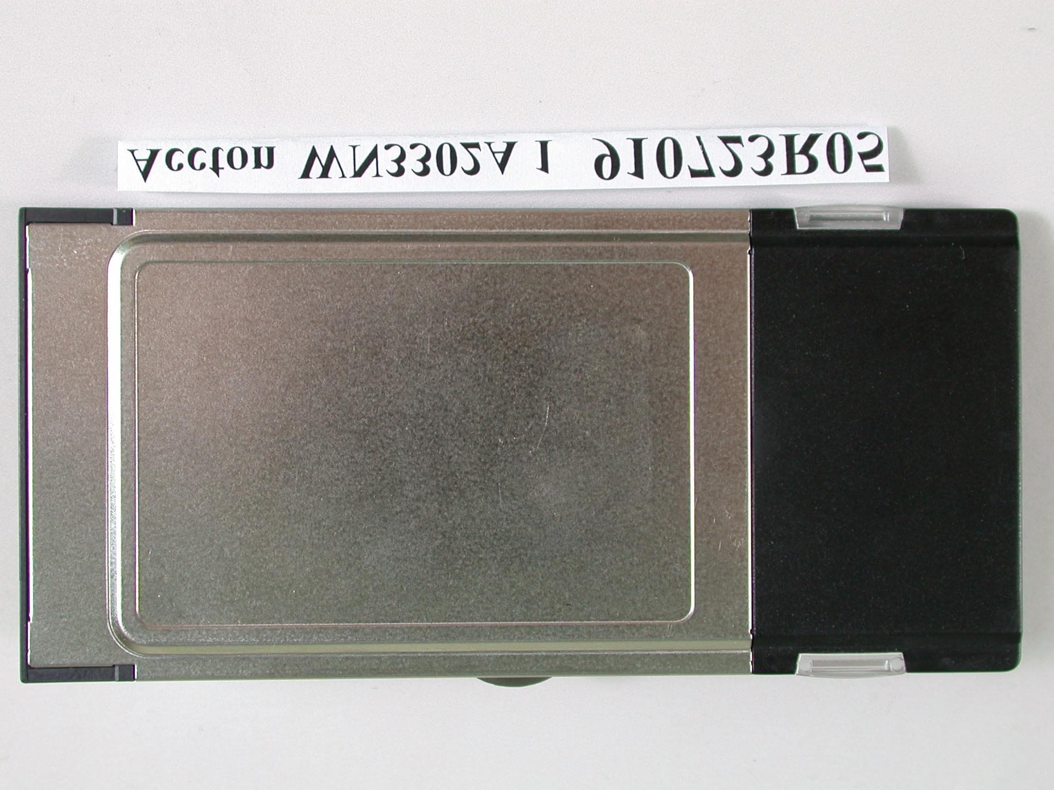
Click to zoom
Application Details
- Equipment Class
- DTS - Digital Transmission System
- Date of Grant
- Oct 16, 2002
- Application Purpose
- Original Equipment
- Date of Application
- Oct 16, 2002
- Equipment Note
- IEEE 802.11b 11 Mbps Wireless LAN Card
- Frequency Range
- 2412.00000000 - 2462.00000000
- Company
- Accton Technology Corp
- Country
- Taiwan
Documents & Files
Document Text
Text extracted from the exhibit documents filed with the FCC. Open a document above to read the original.
Users Manual
IEEE802.11b PCMCIA Card Quick Installation Guide Quick Installation Guide IEEE802.11b PCMCIA Card 11 Mbps Wireless PCMCIA Card The easy way to make all your network connections WN3302A-ZZ E092002-R01 150200004800A i Compliances FCC - Class B This equipment has been tested and found to comply with the limits for a Class B digital device, pursuant to Part 15 of the FCC Rules. These limits are designed to provide reasonable protection against harmful interference in a residential installation. This equipment generates, uses and can radiate radio frequency energy and, if not installed and used in accordance with instructions, may cause harmful and, if not installed and used in accordance with instructions, may cause harmful interference to radio communications. However, there is no guarantee that the interference will not occur in a particular installation. If this equipment does cause harmful interference to radio or television reception, which can be determined by turning the equipment off and on, the user is encouraged to try to correct the interference by one or more of the following measures: • Reorient the receiving antenna • Increase the separation between the equipment and receiver • Connect the equipment into an outlet on a circuit different from that to which the receiver is connected • Consult the dealer or an experienced radio/TV technician for help FCC Caution: To assure continued compliance, (example - use only shielded interface cables when connecting to computer or peripheral devices). Any changes or modifications not expressly approved by the party responsible for compliance could void the user’s authority to operate this equipment. This device complies with Part 15 of the FCC Rules. Operation is subject to the following two conditions: (1) This device may not cause harmful interference, and (2) this device must accept any interference received, including interference that may cause undesired operation. CAUTION STATEMENT: FCC Radiation Exposure Statement This equipment complies with FCC radiation exposure limits set forth for an uncontrolled environment. This transmitter must not be co-located or operating in conjunction with any other antenna or transmitter. In order to maintain compliance with the limits for a Class B digital device, it requires that you use a quality interface cable when connecting to this device. Changes or modifications not expressly approved could void the user’s authority to operate this equipment. Compliances ii Industry Canada - Class B This digital apparatus does not exceed the Class B limits for radio noise emissions from digital apparatus as set out in the interference-causing equipment standard entitled “Digital Apparatus,” ICES-003 of Industry Canada. Cet appareil numérique respecte les limites de bruits radioélectriques applicables aux appareils numériques de Classe B prescrites dans la norme sur le matérial brouilleur: “Appareils Numériques,” NMB-003 édictée par l’Industrie. EC Conformance Declaration - Class B This information technology equipment complies with the requirements of the Council Directive 89/336/EEC on the Approximation of the laws of the Member States relating to Electromagnetic Compatibility and 73/23/EEC for electrical equipment used within certain voltage limits and the Amendment Directive 93/68/EEC. For the evaluation of the compliance with these Directives, the following standards were applied: RFI Emission: • Limit class B according to EN 55022:1998, IEC 60601-1-2 (EMC, medical) • Limit class B for harmonic current emission according to EN 61000-3-2/1995 • Limitation of voltage fluctuation and flicker in low-voltage supply system according to EN 61000-3-3/1995 Immunity: • Product family standard according to EN 55024:1998 • Electrostatic Discharge according to EN 61000-4-2:1995 (Contact Discharge: ±4 kV, Air Discharge: ±8 kV) • Radio-frequency electromagnetic field according to EN 61000-4-3:1996 (80 - 1000 MHz with 1 kHz AM 80% Modulation: 3 V/m) • Electrical fast transient/burst according to EN 61000-4-4:1995 (AC/DC power supply: ±1 kV, Data/Signal lines: ±0.5 kV) • Surge immunity test according to EN 61000-4-5:1995 (AC/DC Line to Line: ±1 kV, AC/DC Line to Earth: ±2 kV) • Immunity to conducted disturbances, Induced by radio-frequency fields: EN 61000-4-6:1996 (0.15 - 80 MHz with 1 kHz AM 80% Modulation: 3 V/m) • Power frequency magnetic field immunity test according to EN 61000-4-8:1993 (1 A/m at frequency 50 Hz) • Voltage dips, short interruptions and voltage variations immunity test according to EN 61000-4-11:1994 (>95% Reduction @10 ms, 30% Reduction @500 ms, >95% Reduction @5000 ms) LVD: • EN 60950 (A1/1992; A2/1993; A3/1993; A4/1995; A11/1997) MDD: • IEC 60601-1 Compliances iii Safety Compliance Wichtige Sicherheitshinweise (Germany) 1. Bitte lesen Sie diese Hinweise sorgfältig durch. 2. Heben Sie diese Anleitung für den späteren Gebrauch auf. 3. Vor jedem Reinigen ist das Gerät vom Stromnetz zu trennen. Verwenden Sie keine Flüssigoder Aerosolreiniger. Am besten eignet sich ein angefeuchtetes Tuch zur Reinigung. 4. Die Netzanschlu ßsteckdose soll nahe dem Gerät angebracht und leicht zugänglich sein. 5. Das Gerät ist vor Feuchtigkeit zu schützen. 6. Bei der Aufstellung des Gerätes ist auf sicheren Stand zu achten. Ein Kippen oder Fallen könnte Beschädigungen hervorrufen. 7. Die Belüftungsöffnungen dienen der Luftzirkulation, die das Gerät vor Überhitzung schützt. Sorgen Sie dafür, daß diese Öffnungen nicht abgedeckt werden. 8. Beachten Sie beim Anschluß an das Stromnetz die Anschlußwerte. 9. Verlegen Sie die Netzanschlußleitung so, daß niemand darüber fallen kann. Es sollte auch nichts auf der Leitung abgestellt werden. 10. Alle Hinweise und Warnungen, die sich am Gerät befinden, sind zu beachten. 11. Wird das Gerät über einen längeren Zeitraum nicht benutzt, sollten Sie es vom Stromnetz trennen. Somit wird im Falle einer Überspannung eine Beschädigung vermieden. 12. Durch die Lüftungsöffnungen dürfen niemals Gegen…
Text truncated - open the document above for the full version.
Users Manual
IEEE802.11b PCMCIA Card Quick Installation Guide Quick Installation Guide IEEE802.11b PCMCIA Card 11 Mbps Wireless PCMCIA Card The easy way to make all your network connections WN3302A-ZZ E092002-R01 150200004800A i Compliances FCC - Class B This equipment has been tested and found to comply with the limits for a Class B digital device, pursuant to Part 15 of the FCC Rules. These limits are designed to provide reasonable protection against harmful interference in a residential installation. This equipment generates, uses and can radiate radio frequency energy and, if not installed and used in accordance with instructions, may cause harmful and, if not installed and used in accordance with instructions, may cause harmful interference to radio communications. However, there is no guarantee that the interference will not occur in a particular installation. If this equipment does cause harmful interference to radio or television reception, which can be determined by turning the equipment off and on, the user is encouraged to try to correct the interference by one or more of the following measures: • Reorient the receiving antenna • Increase the separation between the equipment and receiver • Connect the equipment into an outlet on a circuit different from that to which the receiver is connected • Consult the dealer or an experienced radio/TV technician for help FCC Caution: To assure continued compliance, (example - use only shielded interface cables when connecting to computer or peripheral devices). Any changes or modifications not expressly approved by the party responsible for compliance could void the user’s authority to operate this equipment. This device complies with Part 15 of the FCC Rules. Operation is subject to the following two conditions: (1) This device may not cause harmful interference, and (2) this device must accept any interference received, including interference that may cause undesired operation. CAUTION STATEMENT: FCC Radiation Exposure Statement This equipment complies with FCC radiation exposure limits set forth for an uncontrolled environment. This transmitter must not be co-located or operating in conjunction with any other antenna or transmitter. In order to maintain compliance with the limits for a Class B digital device, it requires that you use a quality interface cable when connecting to this device. Changes or modifications not expressly approved could void the user’s authority to operate this equipment. Compliances ii Industry Canada - Class B This digital apparatus does not exceed the Class B limits for radio noise emissions from digital apparatus as set out in the interference-causing equipment standard entitled “Digital Apparatus,” ICES-003 of Industry Canada. Cet appareil numérique respecte les limites de bruits radioélectriques applicables aux appareils numériques de Classe B prescrites dans la norme sur le matérial brouilleur: “Appareils Numériques,” NMB-003 édictée par l’Industrie. EC Conformance Declaration - Class B This information technology equipment complies with the requirements of the Council Directive 89/336/EEC on the Approximation of the laws of the Member States relating to Electromagnetic Compatibility and 73/23/EEC for electrical equipment used within certain voltage limits and the Amendment Directive 93/68/EEC. For the evaluation of the compliance with these Directives, the following standards were applied: RFI Emission: • Limit class B according to EN 55022:1998, IEC 60601-1-2 (EMC, medical) • Limit class B for harmonic current emission according to EN 61000-3-2/1995 • Limitation of voltage fluctuation and flicker in low-voltage supply system according to EN 61000-3-3/1995 Immunity: • Product family standard according to EN 55024:1998 • Electrostatic Discharge according to EN 61000-4-2:1995 (Contact Discharge: ±4 kV, Air Discharge: ±8 kV) • Radio-frequency electromagnetic field according to EN 61000-4-3:1996 (80 - 1000 MHz with 1 kHz AM 80% Modulation: 3 V/m) • Electrical fast transient/burst according to EN 61000-4-4:1995 (AC/DC power supply: ±1 kV, Data/Signal lines: ±0.5 kV) • Surge immunity test according to EN 61000-4-5:1995 (AC/DC Line to Line: ±1 kV, AC/DC Line to Earth: ±2 kV) • Immunity to conducted disturbances, Induced by radio-frequency fields: EN 61000-4-6:1996 (0.15 - 80 MHz with 1 kHz AM 80% Modulation: 3 V/m) • Power frequency magnetic field immunity test according to EN 61000-4-8:1993 (1 A/m at frequency 50 Hz) • Voltage dips, short interruptions and voltage variations immunity test according to EN 61000-4-11:1994 (>95% Reduction @10 ms, 30% Reduction @500 ms, >95% Reduction @5000 ms) LVD: • EN 60950 (A1/1992; A2/1993; A3/1993; A4/1995; A11/1997) MDD: • IEC 60601-1 Compliances iii Safety Compliance Wichtige Sicherheitshinweise (Germany) 1. Bitte lesen Sie diese Hinweise sorgfältig durch. 2. Heben Sie diese Anleitung für den späteren Gebrauch auf. 3. Vor jedem Reinigen ist das Gerät vom Stromnetz zu trennen. Verwenden Sie keine Flüssigoder Aerosolreiniger. Am besten eignet sich ein angefeuchtetes Tuch zur Reinigung. 4. Die Netzanschlu ßsteckdose soll nahe dem Gerät angebracht und leicht zugänglich sein. 5. Das Gerät ist vor Feuchtigkeit zu schützen. 6. Bei der Aufstellung des Gerätes ist auf sicheren Stand zu achten. Ein Kippen oder Fallen könnte Beschädigungen hervorrufen. 7. Die Belüftungsöffnungen dienen der Luftzirkulation, die das Gerät vor Überhitzung schützt. Sorgen Sie dafür, daß diese Öffnungen nicht abgedeckt werden. 8. Beachten Sie beim Anschluß an das Stromnetz die Anschlußwerte. 9. Verlegen Sie die Netzanschlußleitung so, daß niemand darüber fallen kann. Es sollte auch nichts auf der Leitung abgestellt werden. 10. Alle Hinweise und Warnungen, die sich am Gerät befinden, sind zu beachten. 11. Wird das Gerät über einen längeren Zeitraum nicht benutzt, sollten Sie es vom Stromnetz trennen. Somit wird im Falle einer Überspannung eine Beschädigung vermieden. 12. Durch die Lüftungsöffnungen dürfen niemals Gegen…
Text truncated - open the document above for the full version.
Cover Letter(s)
American Telecommunications Certification Body Inc. 6731 Whittier Ave, McLean, VA 22101 October 2, 2002 RE: ACCTON TECHNOLOGY CORPORATION FCC ID: HEDACCWN3302A-1 After a review of the submitted information, I have a few comments on the above referenced Application. These comments are all made upon the assumption that the EUT's full conducted output power is 32 mW and the antenna gain is -1.0 dBi. 1) The responsible party located on the DoC information sheet must be located within the U.S. Please provide a corrected copy. 2) The EUT is a PCMCIA Card. The operational description and RF exposure exhibits provided state that the device will be positioned 20 cm from the user. General purpose PCMCIA cards must be considered as used in a variety of devices, including laptops & PDA's, etc. Some of these devices may be used in the lap or while on the body. Therefore touch position is considered applicable and the device must be subject to portable exposure conditions. Please provider further information to support the 20 cm or provide RF exposure exhibits meeting the portable category. 3) The users manual states that the output power is +15 dBm minimum, +17 dBm typical. Please note that the maximum output power measured was 15.1 dBm. Please explain as it is assumed that the device may not have been in a maximum TX condition. 4) Please note that the FCC has recently changed how to treat these types of devices (general purpose PCMCIA cards) for MPE/SAR related issues. Both 20 and 2.5 cm are no longer considered acceptable spacing for general PCMCIA cards based upon specific laptop configurations that can occur. The FCC has instructed us that we must consider that these device might be used in a touch position to the body. Assuming this device is for general purpose use please: a) Adjust the appropriate exhibits so that the device should be classified for portable and/or mobile use. b) Since the output power (either conducted or EIRP, Conducted = 32 mW, EIRP = 25.4 mW) exceeds 24.6 mW (60/f calculated), this device will require SAR testing. Please note that testing must be performed in a touch position to the SAR phantom. Alternatively, the power may be lowered such that the conducted and EIRP is less than 24.6 mW. c) If SAR testing is performed, the Users Manual should contain information regarding the device and that it has met with SAR requirements. Additionally the current MPE statements would need to be modified. 5) NOTE: Due to concerns on how to treat the device for RF exposure as given above, the test report has not been reviewed at this time. Timothy R. Johnson Examining Engineer mailto: [email protected] The items indicated above must be submitted before processing can continue on the above referenced application. Failure to provide the requested information may result in application termination. Correspondence should be considered part of the permanent submission and may be viewed from the Internet after a Grant of Equipment Authorization is issued. Please do not respond to this correspondence using the email reply button. In order for your response to be processed expeditiously, you must submit your documents through the AmericanTCB.com website. Also, please note that partial responses increase processing time and should not be submitted. Any questions about the content of this correspondence should be directed to the sender.
Cover Letter(s)
Dear Tim The revised 731 form, RF Exposure and test report have been re-submitted to ATCB website. Have a look please, thank you. Regards Emily To: [email protected] Subject: Review of ACCTON TECH CORP., FCC ID: HEDACCWN3302A-1 Page 1 of 1In 10/13/2002Printed for "Timothy R. Johnson" <[email protected]>
Cover Letter(s)
American Telecommunications Certification Body Inc. 6731 Whittier Ave, McLean, VA 22101 October 13, 2002 RE: ACCTON TECHNOLOGY CORPORATION FCC ID: HEDACCWN3302A-1 After a review of the submitted information, I have a few comments on the above referenced Application. These comments are all made upon the assumption that the EUT's full conducted output power is 18.2 mW and the antenna gain is -1.0 dBi. 1) The responsible party located on the DoC information sheet must be located within the U.S. Please provide a corrected copy. 2) The RF exposure exhibit states the devices classification is mobile. This should be modified to portable since the device may be used as a general purpose PCMCIA card in a variety of devices including laptops & PDA's, etc. (some of these devices may be used in the lap or while on the body). Therefore touch position is considered applicable and the device must be subject to portable exposure conditions. Please provide a modified RF exposure exhibit. 3) Please provide an explanation of how the device has been changed and modified since the first test report provided. Also, please provide an attestation by the manufacturer that the changes will be incorporated into all production models. 4) The users manual states that the output power is +15 dBm minimum, +17 dBm typical. Please note that the maximum output power measured was 12.6 dBm. Please correct the users manual. 5) Since the EUT was retested, please adjust the test dates in the test report given on page 1 & 4. 6) The peak output power given on page 6 does not match the newly measured power. Please adjust the report. Timothy R. Johnson Examining Engineer mailto: [email protected] The items indicated above must be submitted before processing can continue on the above referenced application. Failure to provide the requested information may result in application termination. Correspondence should be considered part of the permanent submission and may be viewed from the Internet after a Grant of Equipment Authorization is issued. Please do not respond to this correspondence using the email reply button. In order for your response to be processed expeditiously, you must submit your documents through the AmericanTCB.com website. Also, please note that partial responses increase processing time and should not be submitted. Any questions about the content of this correspondence should be directed to the sender.
External Photos
Page 1 ANNEX PHOTOGRAPHS OF EUT Page 2
ID Label/Location Info
FCC ID Label Location
ID Label/Location Info
FORM# R0-04D00-13 V.02 XXXXXXXXXXXXE UL Label R01 91 07 12 UL approve MM 0.2MM 20# Black Sylin CHECK: APPROVE: MFG Factory: 1. NatSteel --------------------> AS 2. Accton --------------------------> AC 3. NatSteel------------------ > AI 4. NatSteel ------------> AM 5 Mototech---------------> AV 6. Accton --------------------------> None 7. CIS -------------------------> BH 8. Fair Job--------------------> BJ 9. Orient Semiconductor --> BY MFG Country: Vendor ID: Decide by import and export country Decide by Vendor WN3302A 1 White mylor+pp MFG Country (Arial Narrow, Point 4) MFG Factory (Arial Narrow, Point 4) Vendor ID (Arial Narrow, Point 4) Model:WN3302A 1 0560 ! 4 8 . 0 m m 41.5 mm IEEE802.11b 11Mbps Wireless LAN Card R10*4 Made in XXXXXX XX XXXXXXXXXXXXE R01 Input: DC5V FCC ID:HEDACCWN3302A-1 IC: XXXXXXXXXXXXXX Complies with RSS-210 XXXXXX
Internal Photos
Page 3 Page 4 Page 5
Operational Description
FCC ID: HEDACCWN3302A-1 ADT No.910723R04A Operational Description The transmitter of the EUT (IEEE802.11b 11Mbps Wireless LAN Card) is powered by notebook and plugged in PCMCIA Slot. The antenna is Printed antenna, and there is no antenna connector. Under normal use condition, the user has to keep at least 20cm separation distance between radiator and the body of the user. The other instruction, please have a look at the users manual. DSSS Information This device is Direct Sequence Spread Spectrum, the data is mixed by pseudorandom code which is an orthogonal code. The mixed data is digital modulated by BPSK and QPSK technique depends on the data rates. The CCK coding is applied for increasing the data rate, and also the processing gain will be increased. The bit rates are 1,2,5.5,11Mbps, the symbol rates are 1,1,1.375,1.375Mbps, the chip rates are always 11Mbps. So, the Chip/symbol is 11,11,8 and 8 respectively. Although is higher bit rate, the processing gain is lower than 10, but the CCK coding used in higher bit rate will provide 2.2dB coding gain.
RF Exposure Info
FCC ID: HEDACCWN3302A-1 ADT No.: 910723R04A FCC TEST REPORT REPORT NO.: RF910723R04A MODEL NO.: WN3302A 1 ACCORDING: FCC Guidelines for Human Exposure IEEE C95.1 APPLICANT:ACCTON TECHNOLOGY CORPORATION ADDRESS:No. 1, Creation Rd., III, Science-Based Industrial Park, Hsinchu, Taiwan, R.O.C. ISSUED BY:Advance Data Technology Corporation LAB LOCATION:47 14th Lin, Chiapau Tsun, Linko, Taipei, Taiwan, R.O.C. 0528 ILAC MRA Lab Code: 200102-0 FCC ID: HEDACCWN3302A-1 ADT No.: 910723R04A RF Exposure Measurement (Portable Device) 1. Introduction 2.4 GHz frequency band is regarded specially as a dangerous band for its heating harmfulness to the human body. That’s why microwave oven is operating in this frequency band. The manufacturer whose product is working in this frequency band is obligatory to prove the harmfulness of his product. In this document, we try to prove the safety of radiation harmfulness to the human body for our product. The limit for Maximum Permissible Exposure (MPE) specified in FCC 1.1310 is followed. The Gain of the antenna used in this product is measured in a Fully Anechoic Chamber (FAC), and the maximum total power input to the antenna is measured. Through the Friis transmission formula and the maximum gain of the antenna, we can calculate the distance, away from the product, where the limit of MPE is reached. 2. RF Exposure Limit According to FCC 1.1310: The criteria listed in the following table shall be used to evaluate the environmental impact of human exposure to radio-frequency (RF) radiation as specified in 1.1307(b). FCC ID: HEDACCWN3302A-1 ADT No.: 910723R04A LIMITS FOR MAXIMUM PERMISSIBLE EXPOSURE (MPE) Frequency Range (MHz) Electric Field Strength (V/m) Magnetic Field Strength (A/m) Power Density (mW/cm 2 ) Average Time (minutes) (A)Limits For Occupational / Control Exposures 30-30061.40.1631.06 300-1500......F/3006 1500-100,000......56 (B)Limits For General Population / Uncontrolled Exposure 30-30027.50.0730.230 300-1500......F/150030 1500-100,000......1.030 F = Frequency in MHz 3. Friis Formula Friis transmission formula : Pd = (Pout*G) / (4*pi*r 2 ) where Pd = power density in mW/cm 2 Pout = output power to antenna in mW G = gain of antenna in linear scale Pi = 3.1416 R = distance between observation point and center of the radiator in cm Pd is the limit of MPE, 1 mW/cm 2 . If we know the maximum Gain of the antenna and the total power input to the antenna, through the calculation, we will know the distance r where the MPE limit is reached. Ref. : David K. Cheng, Field and Wave Electromagnetics, Second Edition, Page 640, Eq. (11-133). 4. EUT Operating condition The software provided by Manufacturer enabled the EUT to transmit and receive data at lowest, middle and highest channel individually. FCC ID: HEDACCWN3302A-1 ADT No.: 910723R04A 5. Test Results 5.1 Antenna Gain The maximum Gain measured in Fully Anechoic Chamber is -1 dBi or 0.79 (numeric). 5.2 Output Power Into Antenna & RF Exposure Distance : CHANNEL CHANNEL FREQUENCY (MHz) OUTPUT POWER TO ANTENNA (mW) MINIMUM ALLOWABLE DISTANCE ( r ) FROM SKIN (Centi-Meter) 1241232.361.43 6243731.411.41 11246231.841.42 The minimum allowable distance is very close to the enclosure of the antenna and is very far away from the human being under normal use condition.
Test Report
FCC ID: HEDACCWN3302A-1 Report No.: RF910723R04A 1 Issued: Oct. 9, 2002 Reference No.: RF910723R04 FCC TEST REPORT REPORT NO.: RF910723R04A MODEL NO.: WN3302A 1 RECEIVED: July 23, 2002 TESTED: July 30 ~ Oct. 8, 2002 APPLICANT:ACCTON TECHNOLOGY CORPORATION ADDRESS:No. 1, Creation Rd., III, Science-Based Industrial Park, Hsinchu, Taiwan, R.O.C. ISSUED BY:Advance Data Technology Corporation LAB LOCATION:47 14th Lin, Chiapau Tsun, Linko, Taipei, Taiwan, R.O.C. This test report consists of 49 pages in total. It may be duplicated completely for legal use with the approval of the applicant. It should not be reproduced except in full, without the written approval of our laboratory. The client should not use it to claim product endorsement by CNLA, NVLAP or any government agencies. The test results in the report only apply to the tested sample. 0528 ILAC MRA Lab Code: 200102-0 FCC ID: HEDACCWN3302A-1 Report No.: RF910723R04A 2 Issued: Oct. 9, 2002 Reference No.: RF910723R04 Table of Contents 1CERTIFICATION ........................................................................................... 4 2SUMMARY OF TEST RESULTS................................................................... 5 3GENERAL INFORMATION ........................................................................... 6 3.1GENERAL DESCRIPTION OF EUT ............................................................. 6 3.2DESCRIPTION OF TEST MODES ............................................................... 7 3.3GENERAL DESCRIPTION OF APPLIED STANDARDS............................... 7 3.4DESCRIPTION OF SUPPORT UNITS.......................................................... 8 4TEST TYPES AND RESULTS ...................................................................... 9 4.1CONDUCTED EMISSION MEASUREMENT ................................................ 9 4.1.1LIMITS OF CONDUCTED EMISSION MEASUREMENT ............................. 9 4.1.2TEST INSTRUMENTS .................................................................................. 9 4.1.3TEST PROCEDURES................................................................................. 10 4.1.4DEVIATION FROM TEST STANDARD ....................................................... 10 4.1.5TEST SETUP ...............................................................................................11 4.1.6EUT OPERATING CONDITIONS................................................................ 12 4.1.7TEST RESULTS.......................................................................................... 13 4.2RADIATED EMISSION MEASUREMENT ................................................... 19 4.2.1LIMITS OF RADIATED EMISSION MEASUREMENT ................................ 19 4.2.2TEST INSTRUMENTS ................................................................................ 20 4.2.3TEST PROCEDURES................................................................................. 21 4.2.4DEVIATION FROM TEST STANDARD ....................................................... 21 4.2.5TEST SETUP .............................................................................................. 22 4.2.6EUT OPERATING CONDITIONS................................................................ 22 4.2.7TEST RESULTS.......................................................................................... 23 4.36dB BANDWIDTH MEASUREMENT .......................................................... 27 4.3.1LIMITS OF 6dB BANDWIDTH MEASUREMENT........................................ 27 4.3.2TEST INSTRUMENTS ................................................................................ 27 4.3.3TEST PROCEDURE ................................................................................... 28 4.3.4DEVIATION FROM TEST STANDARD ....................................................... 28 4.3.5TEST SETUP .............................................................................................. 28 4.3.6EUT OPERATING CONDITIONS................................................................ 28 4.3.7TEST RESULTS.......................................................................................... 29 4.4MAXIMUM PEAK OUTPUT POWER .......................................................... 33 4.4.1LIMITS OF MAXIMUM PEAK OUTPUT POWER MEASUREMENT ........... 33 4.4.2TEST INSTRUMENTS ................................................................................ 33 FCC ID: HEDACCWN3302A-1 Report No.: RF910723R04A 3 Issued: Oct. 9, 2002 Reference No.: RF910723R04 4.4.3TEST PROCEDURES................................................................................. 34 4.4.4DEVIATION FROM TEST STANDARD ....................................................... 34 4.4.5TEST SETUP .............................................................................................. 34 4.4.6EUT OPERATING CONDITIONS................................................................ 34 4.4.7TEST RESULTS.......................................................................................... 35 4.5POWER SPECTRAL DENSITY MEASUREMENT ..................................... 36 4.5.1LIMITS OF POWER SPECTRAL DENSITY MEASUREMENT ................... 36 4.5.2TEST INSTRUMENTS ................................................................................ 36 4.5.3TEST PROCEDURE ................................................................................... 37 4.5.4DEVIATION FROM TEST STANDARD ....................................................... 37 4.5.5TEST SETUP .............................................................................................. 37 4.5.6EUT OPERATING CONDITIONS................................................................ 37 4.5.7TEST RESULTS.......................................................................................... 38 4.6BAND EDGES MEASUREMENT ................................................................ 42 4.6.1LIMITS OF BAND EDGES MEASUREMENT ............................................. 42 4.6.2TEST IN…
Text truncated - open the document above for the full version.
Test Setup Photos
FCC ID: HEDACCWN3302A-1 Report No.: RF910723R04A 47 Issued: Oct. 9, 2002 Reference No.: RF910723R04 5 PHOTOGRAPHS OF THE TEST CONFIGURATION CONDUCTED EMISSION TEST FCC ID: HEDACCWN3302A-1 Report No.: RF910723R04A 48 Issued: Oct. 9, 2002 Reference No.: RF910723R04 RADIATED EMISSION TEST
Contact Information
Applicant
Abby Wei(Manager)
Technical Contact
Advance Data Technology CorporationVivi Wang
[email protected]+886-3-327-0910
13-1, Lane 19, WenShan 3rd., St. · Taoyuan · Taiwan
Non-Technical Contact
Advance Data Technology CorporationVivi Wang
[email protected]+886-3-327-0910
Test Firm
Bureau Veritas CPS (H.K.) Ltd. Taoyuan BranchTommy Wu
Technical Specifications
| # | Rule Parts | Frequency Range | Power Output |
|---|---|---|---|
| 1 | 15C | 2.41 GHz - 2.46 GHz | 18.20 mW |
Other Applications from Accton Technology Corp

HEDEAP115
Jan 27, 2026Wi-Fi 7 AP
Equipment Class
NII - Unlicensed National Information Infrastructure TX
HEDEAP112
Oct 13, 2024Wi-Fi 6 IoT Gateway
Equipment Class
DTS - Digital Transmission System
HEDEAP111
Mar 17, 2024Wi-Fi 6 Access Point
Equipment Class
DTS - Digital Transmission System
HEDOAP101E
Oct 24, 2023Outdoor Access Point
Equipment Class
DTS - Digital Transmission System
HEDEAP104
Dec 14, 2022Indoor Wall Plate WiFi 6 Access Point
Equipment Class
DTS - Digital Transmission System