HEDM506BWN3101A-1Wireless LAN Mini PCI Module
Accton Technology Corp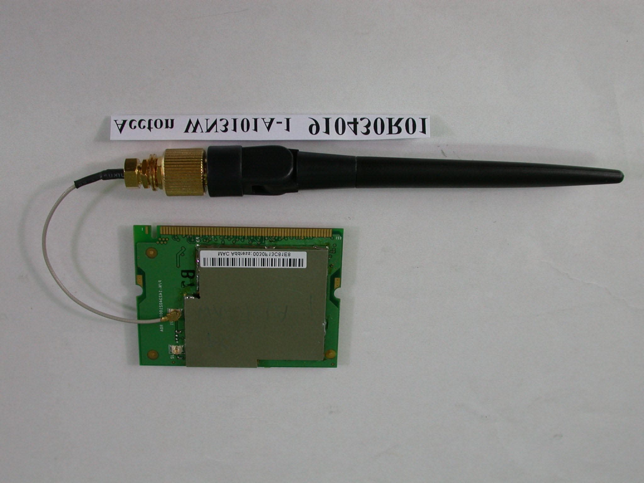
Click to zoom
Application Details
- Equipment Class
- DTS - Digital Transmission System
- Date of Grant
- May 27, 2002
- Application Purpose
- Original Equipment
- Date of Application
- May 27, 2002
- Equipment Note
- Wireless LAN Mini PCI Module
- Frequency Range
- 2412.00000000 - 2462.00000000
- Company
- Accton Technology Corp
- Country
- Taiwan
Documents & Files
Document Text
Text extracted from the exhibit documents filed with the FCC. Open a document above to read the original.
Users Manual
WN3101A-1 11Mbps Wireless Mini PCI Card Quick Installation Guide Setup The WN3101A-1 Mini PCI(TYPE 3B) Card can be used to connect your laptop computer to other wireless equipped laptop computers. Or you can connect to any wired Local Area Network (LAN), including broadband cable modem or DSL connections with the addition of a Wireless Access Point. Windows 98/2000/Me/XP Driver Installation Important: For complete safety precautions and system requirements, please read the User’s Guide. 1. Insert the Mini PCI Card into a Mini PCI slot in your computer. 2. Windows 98/2000/Me/XP will automatically detect the new hardware and prompt you to install the driver needed. 3. Insert the driver diskette into your floppy drive. a. For Windows 98 check the box next to “Specify Location” and browse to A:\. Then click “Ok” to copy files from the disk. b. Windows 2000/Me/XP will automatically locate the driver on the diskette. Click “Ok” to copy files from the disk. 4. After driver installation, the system will re-start the computer. After rebooting, continue the installation for your network protocols and options. 5. Go to “Control Panel” and double-click “Network.” 6. Click “Add...” to install the network protocols you want to use, such as IPX/SPX, NetBEUI or TCP/IP. If you install TCP/IP, be sure to set the appropriate Gateway, DNS Server, and Domain for your network. If you install an IPX/SPX-compatible protocol, then you also need to install the Client for NetWare Networks. 7. Click “File and Print Sharing...” to share files or printers. 9. Click on the “Identification” tab on the Network dialog box, and specify your computer name and network workgroup. 10. Click “Ok” and the system will restart your computer. Windows 98/2000/Me /XP Utility Installation 1. Insert the Utility diskette in your PC floppy drive (A:). 2. Select “Run...” from Windows “Start” menu bar. 3. Click on “Browse ...” to locate the “Setup” file of this program. 4. Then click on “OK” to run the setup program. 5. Follow the on-screen instructions to finish installation. Network Configuration and Planning WN3101A-1 Wireless Mini PCI Card solution supports a stand-alone wireless network configuration, as well as an integrated configuration with 10/100 Mbps Ethernet LANs. The WN3101A-1 can be configured as: • 802.11 Ad Hoc for departmental or SOHO LANs • Infrastructure for enterprise LANs Ad hoc Wireless LAN An Ad Hoc wireless LAN consists of a group of computers, each equipped with one wireless adapter, connected via radio signals as an independent wireless LAN. Computers in a specific Ad hoc wireless LAN must therefore be configured to the same radio channel. An Ad hoc wireless LAN can be used for a branch office or SOHO operation. Infrastructure Wireless LAN The WN3101A-1 can also provide wireless workstations with access to a wired LAN. An integrated wired and wireless LAN is called an Infrastructure configuration. A Basic Service Set (BSS) consists of a group of wireless PC users, and an access point that is directly connected to the wired LAN. Each wireless PC in this BSS can talk to any computer in its wireless group via a radio link, or access other computers or network resources in the wired LAN infrastructure via the access point. Your WN3101A-1 Wireless Mini PCI Card is now fully configured. To configure advanced features, please refe r to the Wireless Mini PCI Card User’s Guide included in this pac kage or visit our website at http://www.accton.com.tw for the latest in product documentation, drivers and utilities. S y s t e m Re quir e me nts B e f o re you i n s t al l t he Cheet ah M i ni P C I A dapt er, c hec k your s y s t em f o r t he f o l l o w i ng requi rem e nt s : • A P C and B I OS t hat s upport t he P C I Loc al B u s S pec i f i c at i o n v 2 .0 o r la te r • An a v a ila b l e b u s - m a s te r i n g ty p e III B 32-bit Mini PCI slot • A n avai l abl e t e l ephone w a l l j a c k f o r m odem c onnec t i on • A 10BASE- T / 100BASE-TX s w it c h or hub ins t alled in y our net w o rk f o r c onnec t i on t o an E t hernet net w o rk Federal Com m uni cati on Com m i ssi on I n terference S t atem ent Thi s equi pm ent has been t e s t ed and f ound t o c o m p l y w i t h t he l i m i t s f o r a Cl as s B di gi t a l devi c e, purs uant t o P a rt 15 of t he FCC Rul e s . Thes e l i m i t s are des i gned t o provi de reas onabl e prot ec t i on agai ns t harm f ul i n t e rf erenc e i n a res i dent i a l i n s t al l a t i on. Thi s equi pm ent generat es , us es and c a n radi at e radi o f r equenc y energy and, i f not i n s t al l ed and us ed i n ac c o rdanc e w i t h t he i n s t ruc t i ons , m a y c aus e harm f ul i n t e rf erenc e t o radi o c o m m uni c a t i ons . How e ver, t here i s no guarant ee t hat int e rf erenc e w ill not oc c u r in a part i c u lar ins t allat i on. I f t h is equipm ent does c aus e harm f ul i n t e rf erenc e t o radi o or t e l e vi s i on rec ept i on, w h i c h c an be det erm i ned by t u rni ng t he equi pm ent of f and on, t he us er i s enc ouraged t o t r y t o c o rrec t t he i n t e rf erenc e by one of t he f o l l o w i ng m eas ures : - Reori ent or rel o c a t e t he rec e i v i ng ant enna. - I n c r eas e t he s eparat i on bet w een t he equi pm ent and rec e i v er. - Connec t t he equi pm ent i n t o an out l e t on a c i rc ui t di f f e rent f r om t hat t o w h i c h t he rec e i v er i s c onnec t ed. - Cons ul t t he deal er or an ex peri enc ed radi o/ TV t e c hni c i an f o r hel p. FCC Caut i on: To as s u re c ont i nued c o m p l i anc e, (ex a m p l e - us e onl y s h i e l ded i n t e rf ac e c abl es w hen c onnec t i ng t o c o m p ut er or peri pheral devi c es ) any c hanges or m odi f i c a t i ons not ex pres s l y approved by t he part y res pons i b l e f o r c o m p l i anc e c oul d voi d t he us er' s aut hori t y t o operat e t h i s equi pm ent . Thi s devi c e c o m p l i e s w i t h P a rt 15 of t he FCC Rul…
Text truncated - open the document above for the full version.
Cover Letter(s)
Accton Technology Corporation No.1 Creation Rd. III, Science – based Industrial Park, Hsin Chu300, Taiwan, R.O.C. Tel:886-5770270 Fax:886-3-5783839 Inform Letter Dear Customer, According to FCC’s regulation, the following Declaration of Conformity has to be made by a company located in USA. They are: This device has been confirmed to be in compliance with the requirements of ANSI C63.4 & FCC part 15 regulations. The test result has been shown in the ADT test report with number RF910430R01. And this compliance is subject to the following two conditions: This device may not cause harmful interference and, This device must accept any interference received, including interference that may cause undesired operation. This declaration can be a separate sheet and be sure that the following message will be also included in this declaration: Product name, model name and trade name. Company name, and address of the one who is responsible for this declaration. Name, title, telephone and fax number as well as the signature of the contact person. Thanks for your attention.
Cover Letter(s)
FCC ID: HEDM506BWN3101A-1 ADT No.910430R01 Modular Approval Request Letter Advance Data Technology May 16, 2002 Dear Application Examiner, Accton Technology Corporation’s Wireless LAN MiniPCI Card, FCC ID: HEDM506BWN3101A-1, would like to have your authorization as a limited modular approval specific to laptop computer with antenna installed around the LCD panel. The requirements of Public Notice DA00-1407 have been met and shown on the following statements. 1. “The modular transmitter must have its own RF shielding.”: The radio portion of this module has been shielded, please see exhibition External Photo. 2. “The modular transmitter must have buffered modulation/data inputs.” The EUT has buffered data inputs, it is integrated in chip HFA 3783. 3. “The modular transmitter must have its own power supply regulation.” The chips IF converter and RF/IF converter which will influence the frequency radiation, have to be 2.84V DC powered. The mini-pci interface provides 3.3VDC, so there are regulators in front of these chips, the part number of this regulator is MAX8885EUK25. 4. “The modular transmitter must comply with the antenna requirements of section 15.203 and 15.204(C).” The EUT meets the FCC antenna requirements. The spurious emission, unique antenna connector and photo of antennas are shown in the test report. 5. “The modular transmitter must be tested in a stand-alone configuration” The EUT was tested in a stand-alone configuration via a PCI to mini-PCI extender. Please see section Photographs of Test Configuration in the test report, the EUT was plugged in this extender. 6. “The modular transmitter must be labeled with its own FCC ID number.” Please see exhibition Label Sample for the FCC ID of this module. And also in the exhibition Users Manual, there are instructions give to the OEM on how to label the end product. FCC ID: HEDM506BWN3101A-1 ADT No.910430R01 7. “The modular transmitter must comply with any specific rule or operating requirements applicable to the transmitter and the manufacturer must provide adequate instructions along with the module to explain any such requirements.” The EUT is compliant with all applicable FCC rules. Detail instructions for maintaining compliance are given in the Users Manual. 8. “The modular transmitter must comply with any applicable RF exposure requirements.” The EUT is compliant with all applicable RF exposure requirements. RF Exposure is addressed in the RF exposure exhibition. Please contact me if you have any further questions. Thanks for your attention. Best Regards, Dr. Alan Lane Manager of R&TTE Division Advance Data Technology
Cover Letter(s)
American Telecommunications Certification Body Inc. 6731 Whittier Ave, McLean, VA 22101 May 17, 2002 RE: Accton Technology Corporation FCC ID: HEDM506BWN3101A-1 I have a few comments on this Application. 1.) Please provide a block diagram with more detail as required by 47CFR 2.1033(b)(5) 2.) Please provide a revised label with the FCC ID: on the same line as Grantee code and product code. 3.) The Manual appears to indicate that this device also contains a modem capable of connecting to a phone line. Is this true? I do not see any PSTN interface on this card. If so, please provide a copy of the suppliers Declaration of Conformity on this device. 4.) There does not appear any prohibition for modifications as required in 47CFR 15.21. William H. Graff President and Examining Engineer mailto: [email protected] The items indicated above must be submitted before processing can continue on the above referenced application. Failure to provide the requested information may result in application termination. Correspondence should be considered part of the permanent submission and may be viewed from the Internet after a Grant of Equipment Authorization is issued. Please do not respond to this correspondence using the email reply button. In order for your response to be processed expeditiously, you must submit your documents through the AmericanTCB.com website. Also, please note that partial responses increase processing time and should not be submitted. Any questions about the content of this correspondence should be directed to the sender.
External Photos
Page 1 ANNEX PHOTOGRAPHS OF EUT Page 2
ID Label/Location Info
FC C I D U S : HE D M 506 BW N 3101A -1
Internal Photos
Page 3 Page 4
Operational Description
FCC ID: HEDM506BWN3101A-1 ADT No.910430R01 Operational Description The transmitter of the EUT (Wireless LAN MiniPCI Card) is powered by mini-PCI interface. The antenna is Dipole Antenna, and the antenna connector type is UFL. Under normal use condition, the user has to keep at least 20cm separation distance between radiator and the body of the user, because this project is seeking the authorization of limited module approval specific to laptop computer with antenna installed around the LCD panel. The other instruction, please have a look at the users manual. DSSS Information This device is Direct Sequence Spread Spectrum, the data is mixed by pseudorandom code which is an orthogonal code. The mixed data is digital modulated by BPSK and QPSK technique depends on the data rates. The CCK coding is applied for increasing the data rate, and also the processing gain will be increased. The bit rates are 1,2,5.5,11Mbps, the symbol rates are 1,1,1.375,1.375Mbps, the chip rates are always 11Mbps. So, the Chip/symbol is 11,11,8 and 8 respectively. Although is higher bit rate, the processing gain is lower than 10, but the CCK coding used in higher bit rate will provide 2.2dB coding gain.
Test Report
FCC ID: HEDM506BWN3101A-1 Report No.: RF910430R01 1 Issued: May 16, 2002 FCC TEST REPORT REPORT NO.: RF910430R01 MODEL NO.: WN3101A-1 WN3101A-1-BI RECEIVED: April 30, 2002 TESTED: April 25 ~ May 3, 2002 APPLICANT:ACCTON TECHNOLOGY CORPORATION ADDRESS: No. 1, Creation Rd., III, Science-Based Industrial Park, Hsinchu, Taiwan, R.O.C. ISSUED BY:Advance Data Technology Corporation LAB LOCATION:47 14th Lin, Chiapau Tsun, Linko, Taipei, Taiwan, R.O.C. This test report consists of 50 pages in total. It may be duplicated completely for legal use with the approval of the applicant. It should not be reproduced except in full, without the written approval of our laboratory. The client should not use it to claim product endorsement by CNLA, NVLAP or any government agencies. The test results in the report only apply to the tested sample. 0528 ILAC MRA Lab Code: 200102-0 FCC ID: HEDM506BWN3101A-1 Report No.: RF910430R01 2 Issued: May 16, 2002 Table of Contents 1CERTIFICATION ........................................................................................... 4 2SUMMARY OF TEST RESULTS................................................................... 5 3GENERAL INFORMATION ........................................................................... 6 3.1GENERAL DESCRIPTION OF EUT ............................................................. 6 3.2DESCRIPTION OF TEST MODES ............................................................... 7 3.3GENERAL DESCRIPTION OF APPLIED STANDARDS............................... 7 3.4DESCRIPTION OF SUPPORT UNITS.......................................................... 8 4TEST TYPES AND RESULTS ...................................................................... 9 4.1CONDUCTED EMISSION MEASUREMENT ................................................ 9 4.1.1LIMITS OF CONDUCTED EMISSION MEASUREMENT ............................. 9 4.1.2TEST INSTRUMENTS .................................................................................. 9 4.1.3TEST PROCEDURES................................................................................. 10 4.1.4TEST SETUP .............................................................................................. 10 4.1.5EUT OPERATING CONDITIONS.................................................................11 4.1.6TEST RESULTS.......................................................................................... 12 4.2RADIATED EMISSION MEASUREMENT ................................................... 18 4.2.1LIMITS OF RADIATED EMISSION MEASUREMENT ................................ 18 4.2.2TEST INSTRUMENTS ................................................................................ 19 4.2.3TEST PROCEDURES................................................................................. 20 4.2.4TEST SETUP .............................................................................................. 21 4.2.5EUT OPERATING CONDITIONS................................................................ 21 4.2.6TEST RESULTS.......................................................................................... 22 4.36dB BANDWIDTH MEASUREMENT .......................................................... 26 4.3.1LIMITS OF 6dB BANDWIDTH MEASUREMENT........................................ 26 4.3.2TEST INSTRUMENTS ................................................................................ 26 4.3.3TEST PROCEDURE ................................................................................... 27 4.3.4TEST SETUP .............................................................................................. 27 4.3.5EUT OPERATING CONDITIONS................................................................ 27 4.3.6TEST RESULTS.......................................................................................... 28 4.4MAXIMUM PEAK OUTPUT POWER .......................................................... 32 4.4.1LIMITS OF MAXIMUM PEAK OUTPUT POWER MEASUREMENT ........... 32 4.4.2TEST INSTRUMENTS ................................................................................ 32 4.4.3TEST PROCEDURES................................................................................. 33 4.4.4TEST SETUP .............................................................................................. 33 4.4.5EUT OPERATING CONDITIONS................................................................ 33 FCC ID: HEDM506BWN3101A-1 Report No.: RF910430R01 3 Issued: May 16, 2002 4.4.6TEST RESULTS.......................................................................................... 34 4.5POWER SPECTRAL DENSITY MEASUREMENT ..................................... 35 4.5.1LIMITS OF POWER SPECTRAL DENSITY MEASUREMENT ................... 35 4.5.2TEST INSTRUMENTS ................................................................................ 35 4.5.3TEST PROCEDURE ................................................................................... 36 4.5.4TEST SETUP .............................................................................................. 36 4.5.5EUT OPERATING CONDITIONS................................................................ 36 4.5.6TEST RESULTS.......................................................................................... 37 4.6BAND EDGES MEASUREMENT ................................................................ 41 4.6.1LIMITS OF BAND EDGES MEASUREMENT ............................................. 41 4.6.2TEST INSTRUMENTS ................................................................................ 41 4.6.3TEST PROCEDURE ................................................................................... 41 4.6.4EUT OPERATING CONDITION .................................................................. 42 4.6.5TEST RESULTS.......................................................................................... 42 4.7ANTENNA REQUIREMENT........................................................................ 45 4.7.1STANDARD APPLIC…
Text truncated - open the document above for the full version.
Test Setup Photos
FCC ID: HEDM506BWN3101A-1 Report No.: RF910430R01 46 Issued: May 16, 2002 5 PHOTOGRAPHS OF THE TEST CONFIGURATION CONDUCTED EMISSION TEST FCC ID: HEDM506BWN3101A-1 Report No.: RF910430R01 47 Issued: May 16, 2002 FCC ID: HEDM506BWN3101A-1 Report No.: RF910430R01 48 Issued: May 16, 2002 RADIATED EMISSION TEST FCC ID: HEDM506BWN3101A-1 Report No.: RF910430R01 49 Issued: May 16, 2002
Contact Information
Applicant
Abby Wei(Manager)
Technical Contact
Advance Data Technology CorporationAlan Lane
[email protected]+886 3 327 0910
13-1, Lane 19, WenShan 3rd St · Taoyuan · Taiwan
Test Firm
Bureau Veritas CPS (H.K.) Ltd. Taoyuan BranchRichard Chen
Technical Specifications
| # | Rule Parts | Frequency Range | Power Output |
|---|---|---|---|
| 1 | 15C | 2.41 GHz - 2.46 GHz | 35.00 mW |
Other Applications from Accton Technology Corp

HEDEAP115
Jan 27, 2026Wi-Fi 7 AP
Equipment Class
NII - Unlicensed National Information Infrastructure TX
HEDEAP112
Oct 13, 2024Wi-Fi 6 IoT Gateway
Equipment Class
DTS - Digital Transmission System
HEDEAP111
Mar 17, 2024Wi-Fi 6 Access Point
Equipment Class
DTS - Digital Transmission System
HEDOAP101E
Oct 24, 2023Outdoor Access Point
Equipment Class
DTS - Digital Transmission System
HEDEAP104
Dec 14, 2022Indoor Wall Plate WiFi 6 Access Point
Equipment Class
DTS - Digital Transmission System