HEDMWG3401N802.11b/g/n 2x2 MIMO Mini Card
Accton Technology Corp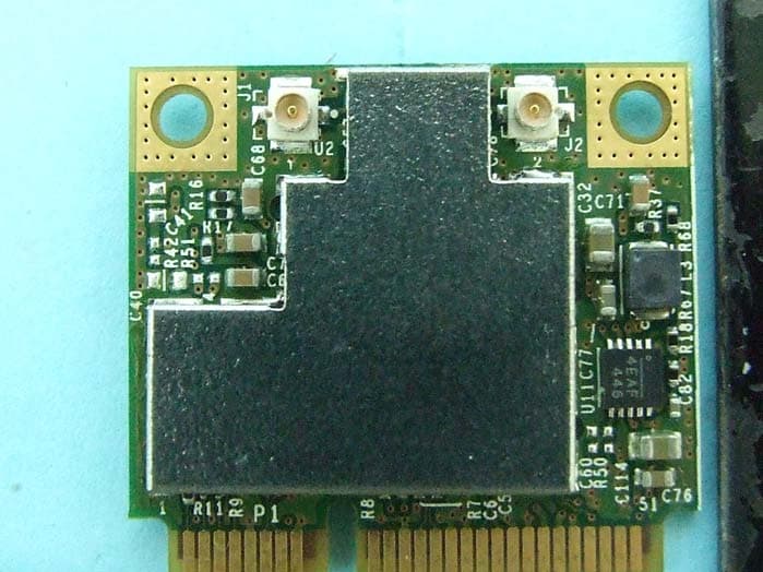
Click to zoom
Application Details
- Equipment Class
- DTS - Digital Transmission System
- Date of Grant
- Dec 20, 2011
- Application Purpose
- Original Equipment
- Date of Application
- Dec 20, 2011
- Equipment Note
- 802.11b/g/n 2x2 MIMO Mini Card
- Frequency Range
- 2422.00000000 - 2452.00000000
- Company
- Accton Technology Corp
- Country
- Taiwan
Documents & Files
Document Text
Text extracted from the exhibit documents filed with the FCC. Open a document above to read the original.
Users Manual
Before you begin Things you should know Network Before you begin Obtain the following information from your network administrator (if you are a home user, obtain this information from the person that installed your wireless access point): l Network names (SSID) of the specific wireless networks that you want to connect to. l WEP (Wired Equivalent Privacy) key information (if any) for the networks you want to connect to. l For Microsoft® Windows® networking, your customer name and workgroup name. l For your network account, your user name and password. l Your IP address (if not using a DHCP server) Things you should know When you start your computer, This module detects certain wireless networks that are within range. Before you can connect to these and other wireless networks, you must configure a profile for each network using the information you obtained from your network administrator. WEP is a security protocol for wireless local area networks (defined in the IEEE 802.11g standard) that encrypts data sent over radio waves. The use of the WEP key is optional and can be enabled or disabled. If the network you are connecting to has enabled WEP, you must also enable WEP in the network profile and set the WEP key to match the WEP key used by the network. Otherwise, you cannot connect to the network. Network This module using Broadcom Wireless Utility to connect network. This module allows you to make a wireless connection to a network, as illustrated below. Back to top Using the Broadcom Wireless Utility: Broadcom AirForce™ 54g™ and Intensi-fi™ Wireless Network Adapter User Guide Back to Contents Page Using the Broadcom Wireless Utility: Broadcom AirForce™ 54g™ and Intensi-fi™ Wireless Network Adapter User Guide Overview Utility Components Overview The Broadcom Wireless Utility enables you to do the following network tasks: l Manage your wireless networks and create network connection profiles (Wireless Networks tab) l Connect to available networks (utility icon in notification area) l Get information about the network status and signal and noise of your network connection (Link Status tab) l View current and accumulated statistics (Statistics tab) l Find out which broadcasting networks are in range and search for nonbroadcasting networks (Site Monitor tab) l Run tests on the wireless network adapter (Diagnostics tab) l Get date and version information about the utility, and software, hardware, and location details about your wireless network adapter ( Information tab) l Manually add or delete trusted servers and enable the manual acceptance or rejection of auto- provisioning and A-ID group changes ( Wireless Networks tab) l Manually import EAP-FAST PACs (Wireless Networks tab) In the utility, you can open Wireless Network Wizard to connect to a basic network or create an ad hoc network, or you can open the Wireless Network Connection Settings tool to connect to an advanced network. To do any of the other tasks, click the tab that is associated with the described task. To start using the utility, right-click the utility icon in the notification area, and then click Open Utility. If the icon is not available, open Broadcom Wireless Utility in Control Panel. NOTE: The utility icon may not appear exactly as shown here. See " Table 1. Signal Strength Indicated by the Broadcom Wireless Utility Icon." Utility Components Utility components include the utility icon in the notification area, the six utility tabs, and Wireless Network Connection Settings. file:///P|/User%20Manuals/WLANCard-UM302_LaLa/HTML/utility.htm (1 of 12)4/25/2006 1:57:41 PM Using the Broadcom Wireless Utility: Broadcom AirForce™ 54g™ and Intensi-fi™ Wireless Network Adapter User Guide Utility Icon To do any of the following tasks or operations, right-click the utility icon, and then click the appropriate item. l Open the on-line Broadcom AirForce™ 54g™ and Intensi-fi™ Wireless Network Adapter User Guide (Help Files) l Open About WLAN Card Utility to view links to Broadcom and Broadcom Customer Support websites and to view the version and date of the utility (About) l Hide the utility icon (Hide Tray Icon) l Disable or enable the radio (Disable/Enable Radio) l Connect to any of the networks for which you have created a connection profile and are within range (Connect To) l Open the utility to the Wireless Networks tab (Open Utility) l Open the utility to the Link Status tab to view information about the connection (Status) l Display a log of your wireless network events (Display Log) Wireless Networks Tab The Wireless Networks tab has tools that enable you to do the following: l Use the utility to manage your wireless networks l Add a network connection profile l Edit or remove a network connection profile l Change the order in which profiles are listed under Preferred network connections l Connect to any listed network without changing its order in the list l Disable or enable the radio (Disable/Enable Radio) l Show or hide the utility icon in the notification area l Choose which type of network to access l Lock or unlock a preferred network connection profile l Save your wireless network connection profiles as a WPN file l Import a WPN file l Manually add or delete trusted servers and enable the manual acceptance or rejection of auto- provisioning and A-ID group changes l Manually import EAP-FAST PACS On the Add menu, you can use either the wireless network wizard that is available from Broadcom Wireless Utility (see Connecting to a Basic Network or Creating an Ad Hoc Network Using the Wireless Network Wizard") or the utility (see "Connecting to an Advanced Network Using the Broadcom Wireless Utility") to add a network connection profile. To use the utility to manage your wireless networks, select the Let this tool manage your wireless networks check box. To add a network connection profile, click the Add arrow, and then click either Use Wizard (basic network) or Use Utility (advanced network). To edit or remove a network co…
Text truncated - open the document above for the full version.
Cover Letter(s)
Page No. : 19 Module Approval Request Letter Subject: Module Approval Date: 2011/12/20 FCC ID: HEDMWG3401N Dear Reviewer, We, Sporton International Inc., are authorized by Accton Technology Corporation to have their state-of-the-art 802.11b/g/n 2x2 MIMO Mini Card approved under full module approval authorization. The application of this module is specified to mobile host equipment. The requirements regulated in Public Notice DA00-1407 have been fulfilled and clearly explained below. 1. The requirement of RF shielding: The shielding of the radio portion can be demonstrated in exhibition External Photo. 2. The requirement of buffered inputs: Buffered data inputs stage has been integrated in chip BCM43225KMLG. 3. The requirement of power supply regulation: The part number of the power regulator is BCM43225KMLG. 4. The requirements of section 15.203 and 15.204(C): The requirements of antenna connector and spurious emission have been fulfilled. Please reference the exhibition Test Report. 5. The requirement of stand-alone test configuration: Please reference exhibition Test Configuration Photo for the stand-alone test configuration. 6. The requirement of labeling: The instruction on the labeling rule of the end product has been stated in the users manual of this module. Please also see the exhibition Label Sample. 7. The requirement of compliance on specific rule or operating requirements: The required FCC rule has been fulfilled and all the instructions for maintaining compliance has been clearly stated in the Users Manual. 8. The requirement of RF exposure: Please refer exhibition RF Exposure for the compliance of MPE RF exposure rule. Please do not hesitate to contact me for any questions of this request letter. Thank you. Company name : Sporton International Inc. Company Address : No.8, Lane 724, Bo-ai St., Jhubei City, Hsinchu County 302, Taiwan, R.O.C. Signature : Name : Leo Huang Job Title : Manager
External Photos
Report No.: 192930 SPORTON International Inc. PAGE NUMBER : A1 OF A2 TEL : 886-2-2696-2468 ISSUED DATE : Nov. 15, 2011 FAX : 886-2-2696-2255 Photographs of EUT Report No.: 192930 SPORTON International Inc. PAGE NUMBER : A2 OF A2 TEL : 886-2-2696-2468 ISSUED DATE : Nov. 15, 2011 FAX : 886-2-2696-2255
ID Label/Location Info
Label drawing and Location Label size : 14 * 6mm Label location (pasted on shield cover as below area) Edge-Core Model: MWG3401N-ZO FCC ID: HEDMWG3401N Label location SMC Model: SMCD3GNB FCC ID: HEDMWG3401N
Internal Photos
Report No.: 192930 SPORTON International Inc. PAGE NUMBER : A1 OF A4 TEL : 886-2-2696-2468 ISSUED DATE : Nov. 15, 2011 FAX : 886-2-2696-2255 Photographs of EUT Report No.: 192930 SPORTON International Inc. PAGE NUMBER : A2 OF A4 TEL : 886-2-2696-2468 ISSUED DATE : Nov. 15, 2011 FAX : 886-2-2696-2255 Report No.: 192930 SPORTON International Inc. PAGE NUMBER : A3 OF A4 TEL : 886-2-2696-2468 ISSUED DATE : Nov. 15, 2011 FAX : 886-2-2696-2255 Report No.: 192930 SPORTON International Inc. PAGE NUMBER : A4 OF A4 TEL : 886-2-2696-2468 ISSUED DATE : Nov. 15, 2011 FAX : 886-2-2696-2255
RF Exposure Info
Report No.: FR192930 FCC ID: HEDMWG3401N Page No. : B1 of B3 Appendix B. Maximum Permissible Exposure Report No.: FR192930 FCC ID: HEDMWG3401N Page No. : B2 of B3 1. Maximum Permissible Exposure 1.1. Applicable Standard Systems operating under the provisions of this section shall be operated in a manner that ensures that the public is not exposed to radio frequency energy levels in excess limit for maximum permissible exposure. In accordance with 47 CFR FCC Part 2 Subpart J, section 2.1091 this device has been defined as a mobile device whereby a distance of 0.25 m normally can be maintained between the user and the device. (A) Limits for Occupational / Controlled Exposure Frequency Range (MHz) Electric Field Strength (E) (V/m) Magnetic Field Strength (H) (A/m) Power Density (S) (mW/ cm²) Averaging Time |E|²,|H|² or S (minutes) 0.3-3.0 614 1.63 (100)* 6 3.0-30 1842 / f 4.89 / f (900 / f)* 6 30-300 61.4 0.163 1.0 6 300-1500 F/300 6 1500-100,000 5 6 (B) Limits for General Population / Uncontrolled Exposure Frequency Range (MHz) Electric Field Strength (E) (V/m) Magnetic Field Strength (H) (A/m) Power Density (S) (mW/ cm²) Averaging Time |E|²,|H|² or S (minutes) 0.3-1.34 614 1.63 (100)* 30 1.34-30 824/f 2.19/f (180/f)* 30 30-300 27.5 0.073 0.2 30 300-1500 F/1500 30 1500-100,000 1.0 30 Note: f = frequency in MHz ; *Plane-wave equivalent power density 1.2. MPE Calculation Method E (V/m) = d GP30 Power Density: Pd (W/m²) = 377 2 E E = Electric field (V/m) P = Average RF output power (W) G = EUT Antenna numeric gain (numeric) d = Separation distance between radiator and human body (m) The formula can be changed to Pd = 2 377 30 d GP From the EUT RF output power, the minimum mobile separation distance, d=0.2m, as well as the gain of the used antenna, the RF power density can be obtained. Report No.: FR192930 FCC ID: HEDMWG3401N Page No. : B3 of B3 1.3. Calculated Result and Limit Antenna Type : PIFA Antenna Max Conducted Power for IEEE 802.11n MCS0 (20MHz): 16.59 dBm Test Mode Min. User Distance (cm) Gain (dBi) Numeric Gain Conducte d Power (dBm) Conducte d Power (mW) Power Density (mW/cm2) Limit of Power Density (S) (mW/cm²) Test Result 2.4G 20 3.20 2.0893 16.5888 45.5907 0.018959 1 Complies
Test Report
SPORTON International Inc. No.8, Lane 724, Bo-ai St., Jhubei City, HsinChu County 302, Taiwan, R.O.C. Ph: 886-3-656-9065 / FAX: 886-3-656-9085 / www.sporton.com.tw Report Format Version: 01 FCC RADIO TEST REPORT Applicant’s company Accton Technology Corporation Applicant Address #1, Creation Rd. III, Science-Based Industrial Park, Hsinchu, Taiwan, R.O.C. FCC ID HEDMWG3401N Manufacturer’s company Accton Technology Corporation Manufacturer Address #1, Creation Rd. III, Science-Based Industrial Park, Hsinchu, Taiwan, R.O.C. Product Name 802.11b/g/n 2x2 MIMO Mini Card Brand Name SMC/ Edge-Core Model Name SMCD3GNB/ MWG3401N-ZO Test Rule 47 CFR FCC Part 15 Subpart C § 15.247 Test Freq. Range 2400 ~ 2483.5MHz Received Date Dec. 02, 2010 Final Test Date Nov. 10, 2011 Submission Type Original Equipment Multiple Listing Please refer to section 3.7 Statement Test result included in this report is for the IEEE 802.11n and IEEE 802.11b/g part of the product. The test result in this report refers exclusively to the presented test model / sample. Without written approval of SPORTON International Inc., the test report shall not be reproduced except in full. The measurements and test results shown in this test report were made in accordance with the procedures and found in compliance with the limit given in ANSI C63.10-2009 and 47 CFR FCC Part 15 Subpart C. The test equipment used to perform the test is calibrated and traceable to NML/ROC. Report No.: FR192930 Report Format Version: 01 Page No. : iof ii FCC ID: HEDMWG3401N Issued Date : Dec. 12, 2011 Table of Contents 1. CERTIFICATE OF COMPLIANCE ......................................................................................................................... 1 2. SUMMARY OF THE TEST RESULT .......................................................................................................................... 2 3. GENERAL INFORMATION .................................................................................................................................. 3 3.1. Product Details....................................................................................................................................................................................3 3.2. Accessories .........................................................................................................................................................................................5 3.3. Table for Filed Antenna.......................................................................................................................................................................5 3.4. Table for Carrier Frequencies .............................................................................................................................................................5 3.5. Table for Test Modes ...........................................................................................................................................................................6 3.6. Table for Testing Locations..................................................................................................................................................................6 3.7. Table for Multiple Listing......................................................................................................................................................................7 3.8. Table for Supporting Units ...................................................................................................................................................................7 3.9. Table for Parameters of Test Software Setting .....................................................................................................................................7 3.10. Test Configurations .............................................................................................................................................................................8 4. TEST RESULT ................................................................................................................................................... 10 4.1. AC Power Line Conducted Emissions Measurement.........................................................................................................................10 4.2. Peak Output Power Measurement ....................................................................................................................................................14 4.3. Average Output Power Measurement ..............................................................................................................................................17 4.4. Power Spectral Density Measurement ..............................................................................................................................................20 4.5. 6dB Spectrum Bandwidth Measurement ..........................................................................................................................................32 4.6. Radiated Emissions Measurement ....................................................................................................................................................41 4.7. Band Edge Emissions Measurement .................................................................................................................................................59 4.8. Antenna Requirements .....................................................................................................................................................................68 5. LIST OF MEASURING EQUIPMENTS ................................................................................................................... 69 6. TEST LOCATION.............................................................................................................................................. 71 7. TAF CERTIFICATE OF ACCREDI…
Text truncated - open the document above for the full version.
Test Setup Photos
Report No.: FR192930 FCC ID: HEDMWG3401N Page No. : 1 of 7 Appendix A. Test Photos Report No.: FR192930 FCC ID: HEDMWG3401N Page No. : 2 of 7 1. Photographs of Conducted Emissions Test Configuration FRONT VIEW REAR VIEW Report No.: FR192930 FCC ID: HEDMWG3401N Page No. : 3 of 7 SIDE VIEW Report No.: FR192930 FCC ID: HEDMWG3401N Page No. : 4 of 7 2. Photographs of Radiated Emissions Test Configuration Test Configuration: 9kHz ~30MHz FRONT VIEW REAR VIEW Report No.: FR192930 FCC ID: HEDMWG3401N Page No. : 5 of 7 Test Configuration: 30MHz~1GHz FRONT VIEW REAR VIEW Report No.: FR192930 FCC ID: HEDMWG3401N Page No. : 6 of 7 Test Configuration: Above 1GHz FRONT VIEW REAR VIEW Report No.: FR192930 FCC ID: HEDMWG3401N Page No. : 7 of 7 SIDE VIEW
Contact Information
Applicant
Abby Wei(Manager)
Test Firm
Sporton International Inc.Alex Chen
Technical Specifications
| # | Rule Parts | Frequency Range | Power Output |
|---|---|---|---|
| 2 | 15C | 2.42 GHz - 2.45 GHz | 277.30 mW |
Other Applications from Accton Technology Corp

HEDEAP115
Jan 27, 2026Wi-Fi 7 AP
Equipment Class
NII - Unlicensed National Information Infrastructure TX
HEDEAP112
Oct 13, 2024Wi-Fi 6 IoT Gateway
Equipment Class
DTS - Digital Transmission System
HEDEAP111
Mar 17, 2024Wi-Fi 6 Access Point
Equipment Class
DTS - Digital Transmission System
HEDOAP101E
Oct 24, 2023Outdoor Access Point
Equipment Class
DTS - Digital Transmission System
HEDEAP104
Dec 14, 2022Indoor Wall Plate WiFi 6 Access Point
Equipment Class
DTS - Digital Transmission System