HEDSPAC750Cloud-Enabled Enterprise Access Point
Accton Technology Corp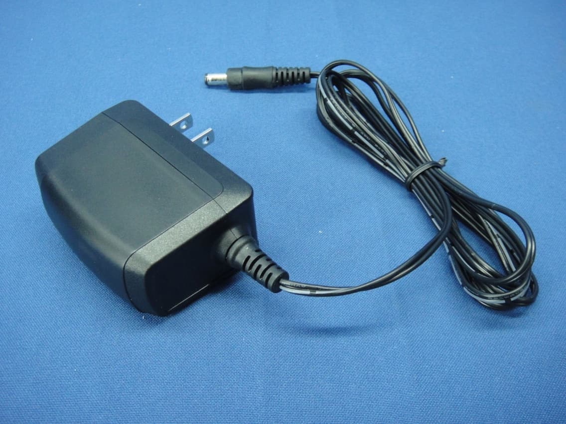
Click to zoom
Application Details
- Equipment Class
- DTS - Digital Transmission System
- Date of Grant
- May 06, 2015
- Application Purpose
- Original Equipment
- Date of Application
- May 06, 2015
- Equipment Note
- Cloud-Enabled Enterprise Access Point
- Frequency Range
- 2412.00000000 - 2462.00000000
- Company
- Accton Technology Corp
- Country
- Taiwan
Documents & Files
Document Text
Text extracted from the exhibit documents filed with the FCC. Open a document above to read the original.
Users Manual
– 1 – Quick Start Guide Cloud-Enabled Enterprise Access Point Spark™ AC750 and Spark™ N300 The Spark AC750 and Spark N300 are dual- and single-band enterprise access points (APs). The units are designed to be operated either placed on a desk or mounted on a wall or ceiling. The package includes a mounting plate for attaching the AP to a wall or ceiling T-bar. The APs can be powered either by the universal power supply included in the package, through an Ethernet cable connection from a Power-over-Ethernet (PoE) injector, or from a 802.3af-compliant PoE switch. The Cloud-Enabled Enterprise Access Point includes these models: ◆SP-AC750 — dual-band concurrent enterprise AP with integrated antennas plus passive Power-over-Ethernet (PoE) ◆SP-AC750-3AF — dual-band concurrent enterprise AP with integrated antennas plus 802.3af Power-over-Ethernet (PoE) ◆SP-N300 — single-band enterprise AP with integrated antennas plus passive Power-over-Ethernet (PoE) ◆SP-N300-3AF — single-band enterprise AP with integrated antennas plus 802.3af Power-over-Ethernet (PoE) Note: For Safety and Regulatory information, refer to the Safety and Regulatory Information document included with the AP. www.ignitenet.com – 2 – Quick Start Guide Follow the steps in this guide to install the AP in your network. Caution: The planning and installation of the AP requires professional personnel that are trained in the installation of radio transmitting equipment. The user is responsible for compliance with local regulations concerning items such as antenna power for instance. Therefore, it is recommended to consult a professional contractor knowledgeable in local radio regulations prior to equipment installation. 1. Unpack the APUnpack the AP and check the package contents. ◆Cloud-Enabled Enterprise Access Point Spark AC750, AC750-3AF, N300, or N300-3AF ◆Mounting plate ◆Mounting kit — 4 screws, 4 wall plugs, and 4 rubber feet ◆Universal AC/DC power adapter ◆Documentation —Quick Start Guide and Regulatory and Safety Information 2. Mount the AP Using the AP on a desktop If the AP is not mounted on a wall or on the ceiling, place the provided rubber feet on the AP. 1 1 1 1 Desktop Mounting Place the provided rubber feet over the four screw holes. 1 – 3 – Quick Start Guide Mounting the AP on a wall Mount the unit on a wall using the mounting plate, screws, and wall plugs provided in the mounting kit. Wall Mounting At the installation location, hold the mounting plate against the wall with its release tab pointing down. Mark the four holes for the wall plugs and screws. Drill four holes for the wall plugs, and then insert the plugs and tap them flush with the wall surface. Align the mounting plate with the four holes, and then use the four screws to secure it to the wall. With its ports facing down, place the AP against the wall above the mounting plate. Slide the rails on the back of the AP down onto the mounting plate until it snaps into its secured position. Do not let go of the AP until you confirm that it is secure. 1 2 1 2 – 4 – Quick Start Guide Mounting the AP on the ceiling If the room is equipped with a suspended ceiling, use the mounting plate provided in the package to attach the AP to the metal ceiling T-bars. The mounting plate supports two different sizes of suspended ceiling T-bars. The position illustrated below is for 15 mm bars. Use the position at a 90 degrees angle for 24.5 mm bars. 2 2 3 Suspended Ceiling Mounting Press the retention clips of the mounting plate against the ceiling T-bar. Rotate the plate until the T-bar snaps into place. Slide the rails on the back of the AP along the sides of the ceiling mounting plate until it snaps into its secured position. 1 2 3 1 1 – 5 – Quick Start Guide 3. Connect CablesConnect Ethernet cable to the 1000BASE-T (WAN /PoE) port on the unit. 4. Connect PowerThe AP can be powered either by the AC/DC power adapter provided in the package, by a PoE power injector (Spark AC750 and N300), or by an 802.3af/at PoE switch (Spark AC750-3AF and N300-3AF). Powering the AP with the AC/DC Power Adapter Powering the AP with a PoE Injector or PoE Switch Connect Ethernet cable from the WAN/PoE port of the AP to a port on the PoE power source device: ◆Spark AC750 and N300 — a PoE power injector (passive PoE, 24-48 VDC). ◆Spark AC750-3AF and N300-3AF — an 802.3af/at-compliant PoE switch. Make sure that the PoE power injector or switch is connected to the LAN. Note: Connecting the Ethernet cable from the AP to a PoE injector or PoE switch powers on the unit. Connect Category 5e or better cable to the WAN/PoE RJ-45 port. Connect the other end of this cable to a PoE injector or LAN PoE switch (depending on AP model). (Optional) Connect local LAN devices to any of the other RJ-45 ports on the AP using Category 5 or better cable. These 100BASE-TX ports are labeled LAN1 and LAN2. 1 2 1 2 Connect the cable from the power adapter to the DC power jack on the AP. Connect the power adapter to a nearby AC power source (100-240 VAC, 50/60 Hz). 1 1 – 6 – Quick Start Guide 5. Verify AP OperationVerify basic AP operation by checking the system LEDs. 6. Connect to the Web User Interface When managed in a stand-alone mode, the AP offers a web-based management interface for the configuration of all the unit’s features. If cloud-managing the AP, go directly to “Manage the AP with the IgniteNet Cloud Controller” on page 7. To access the web interface, connect a PC directly to the AP’s LAN1 or LAN2 RJ-45 port. You must first set your PC IP address to be on the same subnet as the AP (that is, the PC and AP addresses must both start 192.168.2.x with a subnet mask of 255.255.255.0). In a web browser, enter the AP’s default management IP address of 192.168.2.1 to access the web login page. Note: To reset the AP to factory default settings, press and hold down the AP’s Reset button for 5 seconds. The WA N/ Po E port link/activity LED should be on/blinking green. When connected, the LAN1 and LAN2 port link/activity LED…
Text truncated - open the document above for the full version.
Attestation Statements
Accton Technology Corporation No.1, Creation Rd. III, Science-based Industrial Park, Hsinchu, Taiwan, R.O.C. Declaration for no non‐US channel operation May 4, 2015 FCC ID: HEDSPAC750 We, Accton Technology Corporation declare that the device does not support channel 12 ~ 13 in 2.4GHz band and any non‐US channels in all the operational mode(s) for the following product. If you should have any question(s) regarding this declaration, please don’t hesitate to contact us. Thank you! ‐‐‐‐‐‐‐‐‐‐‐‐‐‐‐‐‐‐‐‐‐‐‐‐‐‐‐‐‐‐‐‐‐‐‐‐‐‐‐‐‐‐‐‐‐‐‐‐‐‐‐‐‐‐‐ Mike Peng Accton Technology Corporation Tel.: +886‐3‐5770270 #1874 Fax: +886‐3‐578‐7550 E‐mail: [email protected]
Attestation Statements
Accton Technology Corporation No.1, Creation Rd. III, Science-based Industrial Park, Hsinchu, Taiwan, R.O.C. PROFESSIONAL INSTALLATION ATTESTATION Date: 2015‐05‐04 FCC ID: HEDSPAC750 To Whom It May Concern: Please be advised that due to the unique Market and function targeted by this product, this product will need special trained professional in configuring and installing the product. We hereby declare that the product will be distributed through controlled distribution channel which has special trained professional to install this product and will not be sold directly to the general public through retail store. Thank you for your attention. Sincerely yours, ------------------------------------------------------- Mike Peng Accton Technology Corporation Tel.: +886-3-5770270 #1874 Fax: +886-3-578-7550 E-mail: [email protected]
Cover Letter(s)
Accton Technology Corporation No.1, Creation Rd. III, Science-based Industrial Park, Hsinchu, Taiwan, R.O.C. Date: 2015‐05‐04 FCC ID: HEDSPAC750 AUTHORIZATION LETTER To whom it may concern: We, the undersigned, hereby authorize (name: Amanda Wu and Title: Senior Specialist)of Bureau Veritas Consumer Products Services (H.K.) Ltd., Taoyuan Branch (BV CPS Taoyuan) of Taiwan to act on our behalf in all manners relating to FCC application for equipment authorization, including signing of all documents relating to these matters. Any and all acts carried out by (name: Amanda Wu and Title: Senior Specialist) of BV CPS Taoyuan on our behalf shall have the same effect as acts of our own. If you have any questions regarding the authorization, please don’t hesitate to contact us. Sincerely yours, ------------------------------------------------------- Mike Peng Accton Technology Corporation Tel.: +886-3-5770270 #1874 Fax: +886-3-578-7550 E-mail: [email protected]
Cover Letter(s)
Accton Technology Corporation No.1, Creation Rd. III, Science-based Industrial Park, Hsinchu, Taiwan, R.O.C. Date: 2015‐05‐04 FCC ID: HEDSPAC750 To the attention of Federal Communications Commission Authorization and Evaluation Division Confidentiality Request Pursuant to Sections 0.457 and 0.459 of the Commission’s Rules, the Applicant hereby requests confidential treatment of information accompanying this Application as outlined below: Schematics Block Diagram Software Operational Description The above materials contain trade secrets and proprietary information not customarily released to the public. The public disclosure of these matters might be harmful to the Applicant and provide unjustified benefits to its competitors. The Applicant understands that pursuant to Rule 0.457, disclosure of this Application and all accompanying documentation will not be made before the date of the Grant for this application. Sincerely yours, ------------------------------------------------------- Mike Peng Accton Technology Corporation Tel.: +886-3-5770270 #1874 Fax: +886-3-578-7550 E-mail: [email protected]
Cover Letter(s)
Accton Technology Corporation No.1, Creation Rd. III, Science-based Industrial Park, Hsinchu, Taiwan, R.O.C. Date: 2015‐05‐04 FCC ID: HEDSPAC750 To the attention of Federal Communications Commission Authorization and Evaluation Division Confidentiality Request Pursuant to Sections 0.457 and 0.459 of the commission’s rules, we request short‐term confidential treatment for the following information until (2015/10/30) in order to ensure sensitive business information remains confidential until the actual marketing of the device: External photos Te s t Setup photos User’s manual Internal Photos Sincerely yours, ------------------------------------------------------- Mike Peng Accton Technology Corporation Tel.: +886-3-5770270 #1874 Fax: +886-3-578-7550 E-mail: [email protected]
External Photos
Report No.: 150415E06 Page No. 1 / 28 CONSTRUCTION PHOTOS OF EUT Model No.: SP-AC750 Report No.: 150415E06 Page No. 14 / 28 Model No.: SP-N300 Report No.: 150415E06 Page No. 25 / 28 Adapter Report No.: 150415E06 Page No. 26 / 28 Report No.: 150415E06 Page No. 27 / 28 POE Report No.: 150415E06 Page No. 28 / 28
ID Label/Location Info
246000001307A UL LABEL EAP122030R-1014-ACN Carry MAR24'15 Melody MAR24'15 01 FCC ID: HEDSPAC750 LABEL LOCATION Brad name : IgniteNet Model name : SP-AC750
Internal Photos
Report No.: 150415E06Page No. 2 / 28 Model No.: SP-AC750 Report No.: 150415E06Page No. 3 / 28 Report No.: 150415E06Page No. 4 / 28 Report No.: 150415E06Page No. 5 / 28 Report No.: 150415E06Page No. 6 / 28 Report No.: 150415E06Page No. 7 / 28 Report No.: 150415E06Page No. 8 / 28 Antenna 1 Report No.: 150415E06Page No. 9 / 28 Report No.: 150415E06Page No. 10 / 28 Antenna 2 Report No.: 150415E06Page No. 11 / 28 Report No.: 150415E06Page No. 12 / 28 Antenna 3 Report No.: 150415E06Page No. 13 / 28 Report No.: 150415E06Page No. 15 / 28 Model No.: SP-N300 Report No.: 150415E06Page No. 16 / 28 Report No.: 150415E06Page No. 17 / 28 Report No.: 150415E06Page No. 18 / 28 Report No.: 150415E06Page No. 19 / 28 Report No.: 150415E06Page No. 20 / 28 Report No.: 150415E06Page No. 21 / 28 Antenna 1 Report No.: 150415E06Page No. 22 / 28 Report No.: 150415E06Page No. 23 / 28 Antenna 2 Report No.: 150415E06Page No. 24 / 28
RF Exposure Info
Report No.: SA150415E06 Page No. 1 / 6 Report Format Version: 6.1.1 RF Exposure Report Report No.: SA150415E06 FCC ID: HEDSPAC750 Test Model: SP-AC750 Series Model: SP-N300 Received Date: Apr. 15, 2015 Test Date: Apr. 20, 2015 Issued Date: Apr. 29, 2015 Applicant: Accton Technology Corporation Address: No.1, Creation Rd. III, Science-based Industrial Park, Hsinchu, Taiwan, R.O.C. Issued By: Bureau Veritas Consumer Products Services (H.K.) Ltd., Taoyuan Branch Hsin Chu Laboratory Lab Address: No. 81-1, Lu Liao Keng, 9th Ling,Wu Lung Tsuen, Chiung Lin Hsiang, Hsin Chu Hsien 307, Taiwan R.O.C. Test Location (1): No. 81-1, Lu Liao Keng, 9th Ling,Wu Lung Tsuen, Chiung Lin Hsiang, Hsin Chu Hsien 307, Taiwan R.O.C. Test Location (2): No. 49, Ln. 206, Wende Rd., Shangshan Tsuen, Chiung Lin Hsiang, Hsin Chu Hsien 307, Taiwan R.O.C. This report is for your exclusive use. Any copying or replication of this report to or for any other person or entity, or use of our name or trademark, is permitted only with our prior written permission. This report sets forth our findings solely with respect to the test samples identified herein. The results set forth in this report are not indicative or representative of the quality or characteristics of the lot from which a test sample was taken or any similar or identical product unless specifically and expressly noted. Our report includes all of the tests requested by you and the results thereof based upon the information that you provided to us. You have 60 days from date of issuance of this report to notify us of any material error or omission caused by our negligence, provided, however, that such notice shall be in writing and shall specifically address the issue you wish to raise. A failure to raise such issue within the prescribed time shall constitute your unqualified acceptance of the completeness of this report, the tests conducted and the correctness of the report contents. Unless specific mention, the uncertainty of measurement has been explicitly taken into account to declare the compliance or non-compliance to the specification. The report must not be used by the client to claim product certification, approval, or endorsement by any government agencies. Report No.: SA150415E06 Page No. 2 / 6 Report Format Version: 6.1.1 Table of Contents Release Control Record .................................................................................................................................. 3 1 Certificate of Conformity ...................................................................................................................... 4 2 RF Exposure .......................................................................................................................................... 5 2.1 Limits For Maximum Permissible Exposure (MPE) ............................................................................. 5 2.2 MPE Calculation Formula ................................................................................................................... 5 2.3 Classification ....................................................................................................................................... 5 3 Antenna Gain ......................................................................................................................................... 5 4 Calculation Result of Maximum Conducted Power ........................................................................... 6 Report No.: SA150415E06 Page No. 3 / 6 Report Format Version: 6.1.1 Release Control Record Issue No. Description Date Issued SA150415E06 Original release. Apr. 29, 2015 Report No.: SA150415E06 Page No. 5 / 6 Report Format Version: 6.1.1 2 RF Exposure 2.1 Limits For Maximum Permissible Exposure (MPE) Frequency Range (MHz) Electric Field Strength (V/m) Magnetic Field Strength (A/m) Power Density (mW/cm 2 ) Average Time (minutes) Limits For General Population / Uncontrolled Exposure 300-1500 ... ... F/1500 30 1500-100,000 ... ... 1.0 30 F = Frequency in MHz 2.2 MPE Calculation Formula Pd = (Pout*G) / (4*pi*r 2 ) where Pd = power density in mW/cm 2 Pout = output power to antenna in mW G = gain of antenna in linear scale Pi = 3.1416 R = distance between observation point and center of the radiator in cm 2.3 Classification The antenna of this product, under normal use condition, is at least 20cm away from the body of the user. So, this device is classified as Mobile Device. 3 Antenna Gain 2.4GHz Band Antenna No. PCB Chain No. Ant. Gain(dBi) Frequency Range (GHz to GHz) Ant. Type Connecter Type Cable Length (mm) 1 (White) Chain (0) 4.3 2.4~2.4835 PCB i-pex(MHF) 130 2 (Gray) Chain (1) 4.01 2.4~2.4835 PCB i-pex(MHF) 90 **For 802.11bg mode will fix transmission on Chain (0). 5GHz Band Antenna No. Ant. Gain(dBi) Frequency Range (GHz to GHz) Ant. Type Connecter Type Cable Length (mm) 3 (Black) 5 5.15~5.85 PCB MMCX-plug 115 Report No.: SA150415E06 Page No. 6 / 6 Report Format Version: 6.1.1 4 Calculation Result of Maximum Conducted Power Frequency Band (MHz) Max Power (mW) Antenna Gain (dBi) Distance (cm) Power Density (mW/cm 2 ) Limit (mW/cm 2 ) 2412-2462 929.584 4.3 20 0.49776 1 5180-5240, 5745-5825 411.15 5 20 0.25866 1 Conclusion: Both of the 2.4GHz and 5GHz can transmit simultaneously, the formula of calculated the MPE is: CPD 1 / LPD 1 + CPD 2 / LPD 2 + ......etc. < 1 CPD = Calculation power density LPD = Limit of power density Therefore, the worst-case situation is 0.49776 / 1 + 0.25866 / 1 = 0.756, which is less than “1”. --- END ---
Test Report
Report No.: RF150415E06 Page No. 1 / 58 Report Format Version: 6.1.1 FCC Test Report Report No.: RF150415E06 FCC ID: HEDSPAC750 Test Model: SP-AC750 Series Model: SP-N300 Received Date: Apr. 15, 2015 Test Date: Apr. 16 to 22, 2015 Issued Date: Apr. 29, 2015 Applicant: Accton Technology Corporation Address: No.1, Creation Rd. III, Science-based Industrial Park, Hsinchu, Taiwan, R.O.C. Issued By: Bureau Veritas Consumer Products Services (H.K.) Ltd., Taoyuan Branch Hsin Chu Laboratory Lab Address: No. 81-1, Lu Liao Keng, 9th Ling,Wu Lung Tsuen, Chiung Lin Hsiang, Hsin Chu Hsien 307, Taiwan R.O.C. Test Location (1): No. 81-1, Lu Liao Keng, 9th Ling,Wu Lung Tsuen, Chiung Lin Hsiang, Hsin Chu Hsien 307, Taiwan R.O.C. Test Location (2): No. 49, Ln. 206, Wende Rd., Shangshan Tsuen, Chiung Lin Hsiang, Hsin Chu Hsien 307, Taiwan R.O.C. This report is for your exclusive use. Any copying or replication of this report to or for any other person or entity, or use of our name or trademark, is permitted only with our prior written permission. This report sets forth our findings solely with respect to the test samples identified herein. The results set forth in this report are not indicative or representative of the quality or characteristics of the lot from which a test sample was taken or any similar or identical product unless specifically and expressly noted. Our report includes all of the tests requested by you and the results thereof based upon the information that you provided to us. You have 60 days from date of issuance of this report to notify us of any material error or omission caused by our negligence, provided, however, that such notice shall be in writing and shall specifically address the issue you wish to raise. A failure to raise such issue within the prescribed time shall constitute your unqualified acceptance of the completeness of this report, the tests conducted and the correctness of the report contents. Unless specific mention, the uncertainty of measurement has been explicitly taken into account to declare the compliance or non-compliance to the specification. The report must not be used by the client to claim product certification, approval, or endorsement by TAF or any government agencies. Report No.: RF150415E06 Page No. 2 / 58 Report Format Version: 6.1.1 Table of Contents Release Control Record .................................................................................................................................. 4 1 Certificate of Conformity ...................................................................................................................... 5 2 Summary of Test Results ..................................................................................................................... 6 2.1 Measurement Uncertainty ................................................................................................................... 6 2.2 Modification Record ............................................................................................................................ 6 3 General Information .............................................................................................................................. 7 3.1 General Description of EUT ................................................................................................................ 7 3.2 Description of Test Modes ................................................................................................................... 9 3.2.1 Test Mode Applicability and Tested Channel Detail ........................................................................... 10 3.3 Duty Cycle of Test Signal .................................................................................................................. 12 3.4 Description of Support Units ............................................................................................................. 13 3.4.1 Configuration of System under Test .................................................................................................. 14 3.5 General Description of Applied Standards ........................................................................................ 16 4 Test Types and Results ...................................................................................................................... 17 4.1 Radiated Emission and Bandedge Measurement ............................................................................. 17 4.1.1 Limits of Radiated Emission and Bandedge Measurement .............................................................. 17 4.1.2 Test Instruments ................................................................................................................................ 18 4.1.3 Test Procedures ................................................................................................................................. 20 4.1.4 Deviation from Test Standard ............................................................................................................ 20 4.1.5 Test Set Up ........................................................................................................................................ 21 4.1.6 EUT Operating Conditions ................................................................................................................. 21 4.1.7 Test Results ....................................................................................................................................... 22 4.2 Conducted Emission Measurement .................................................................................................. 35 4.2.1 Limits of Conducted Emission Measurement .................................................................................... 35 4.2.2 Test Instruments ................................................................................................................................ 35 4.2.3 Test Procedures .…
Text truncated - open the document above for the full version.
Test Report
Report No.: RF150415E06-1 Page No. 1 / 61 Report Format Version:6.1.1 FCC Test Report Report No.: RF150415E06-1 FCC ID: HEDSPAC750 Test Model: SP-AC750 Series Model: SP-N300 Received Date: Apr. 15, 2015 Test Date: Apr. 16 to 22, 2015 Issued Date: Apr. 29, 2015 Applicant: Accton Technology Corporation Address: No.1, Creation Rd. III, Science-based Industrial Park, Hsinchu, Taiwan, R.O.C. Issued By: Bureau Veritas Consumer Products Services (H.K.) Ltd., Taoyuan Branch Hsin Chu Laboratory Lab Address: No. 81-1, Lu Liao Keng, 9th Ling,Wu Lung Tsuen, Chiung Lin Hsiang, Hsin Chu Hsien 307, Taiwan R.O.C. Test Location (1): No. 81-1, Lu Liao Keng, 9th Ling,Wu Lung Tsuen, Chiung Lin Hsiang, Hsin Chu Hsien 307, Taiwan R.O.C. Test Location (2): No. 49, Ln. 206, Wende Rd., Shangshan Tsuen, Chiung Lin Hsiang, Hsin Chu Hsien 307, Taiwan R.O.C. This report is for your exclusive use. Any copying or replication of this report to or for any other person or entity, or use of our name or trademark, is permitted only with our prior written permission. This report sets forth our findings solely with respect to the test samples identified herein. The results set forth in this report are not indicative or representative of the quality or characteristics of the lot from which a test sample was taken or any similar or identical product unless specifically and expressly noted. Our report includes all of the tests requested by you and the results thereof based upon the information that you provided to us. You have 60 days from date of issuance of this report to notify us of any material error or omission caused by our negligence, provided, however, that such notice shall be in writing and shall specifically address the issue you wish to raise. A failure to raise such issue within the prescribed time shall constitute your unqualified acceptance of the completeness of this report, the tests conducted and the correctness of the report contents. Unless specific mention, the uncertainty of measurement has been explicitly taken into account to declare the compliance or non-compliance to the specification. The report must not be used by the client to claim product certification, approval, or endorsement by TAF or any government agencies. Report No.: RF150415E06-1 Page No. 2 / 61 Report Format Version:6.1.1 Table of Contents Release Control Record .................................................................................................................................. 4 1 Certificate of Conformity ...................................................................................................................... 5 2 Summary of Test Results ..................................................................................................................... 6 2.1 Measurement Uncertainty ................................................................................................................... 6 2.2 Modification Record ............................................................................................................................ 6 3 General Information .............................................................................................................................. 7 3.1 General Description of EUT ................................................................................................................ 7 3.2 Description of Test Modes ................................................................................................................... 9 3.2.1 Test Mode Applicability and Tested Channel Detail ........................................................................... 10 3.3 Duty Cycle of Test Signal .................................................................................................................. 12 3.4 Description of Support Units ............................................................................................................. 13 3.4.1 Configuration of System under Test .................................................................................................. 14 3.5 General Description of Applied Standard .......................................................................................... 16 4 Test Types and Results ...................................................................................................................... 17 4.1 Radiated Emission and Bandedge Measurement ............................................................................. 17 4.1.1 Limits of Radiated Emission and Bandedge Measurement .............................................................. 17 4.1.2 Test Instruments ................................................................................................................................ 18 4.1.3 Test Procedure .................................................................................................................................. 20 4.1.4 Deviation from Test Standard ............................................................................................................ 20 4.1.5 Test Setup .......................................................................................................................................... 21 4.1.6 EUT Operating Condition .................................................................................................................. 21 4.1.7 Test Results ....................................................................................................................................... 22 4.2 Conducted Emission Measurement .................................................................................................. 41 4.2.1 Limits of Conducted Emission Measurement .................................................................................... 41 4.2.2 Test Instruments ................................................................................................................................ 41 4.2.3 Test Proced…
Text truncated - open the document above for the full version.
Test Setup Photos
Report No.: 140717E01A-1 1 of 3 Reference No.: 140805E09 PHOTOGRAPHS OF THE TEST CONFIGURATION CONDUCTED EMISSION TEST (Mode 1) Report No.: 140717E01A-1 2 of 3 Reference No.: 140805E09 CONDUCTED EMISSION TEST (Mode 2) Report No.: 140717E01A-1 3 of 3 Reference No.: 140805E09 RADIATED EMISSION TEST
Contact Information
Applicant
Abby Wei(Manager)
Test Firm
Bureau Veritas CPS (H.K.) Ltd., Taoyuan BranchRichard Chen
Technical Specifications
| # | Rule Parts | Frequency Range | Power Output |
|---|---|---|---|
| 1 | 15C | 2.41 GHz - 2.46 GHz | 930.00 mW |
Other Applications from Accton Technology Corp

HEDEAP115
Jan 27, 2026Wi-Fi 7 AP
Equipment Class
NII - Unlicensed National Information Infrastructure TX
HEDEAP112
Oct 13, 2024Wi-Fi 6 IoT Gateway
Equipment Class
DTS - Digital Transmission System
HEDEAP111
Mar 17, 2024Wi-Fi 6 Access Point
Equipment Class
DTS - Digital Transmission System
HEDOAP101E
Oct 24, 2023Outdoor Access Point
Equipment Class
DTS - Digital Transmission System
HEDEAP104
Dec 14, 2022Indoor Wall Plate WiFi 6 Access Point
Equipment Class
DTS - Digital Transmission System