HEDVG2211IPersonal Mobile Gateway
Accton Technology Corp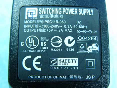
Click to zoom
Application Details
- Equipment Class
- DTS - Digital Transmission System
- Date of Grant
- Jan 19, 2006
- Application Purpose
- Original Equipment
- Date of Application
- Jan 19, 2006
- Equipment Note
- Personal Mobile Gateway
- Frequency Range
- 2412.00000000 - 2462.00000000
- Company
- Accton Technology Corp
- Country
- Taiwan
Documents & Files
Document Text
Text extracted from the exhibit documents filed with the FCC. Open a document above to read the original.
Users Manual
WA6102-ZZ VG007 Personal Mobile Gateway Installation Guide Ins tallati on Guid e G uide Personal Mobile Gateway VoIP Internet Gateway wit h IE EE 80 2.11 b/g Wirele ss Acc ess Point , IE EE 802 .11 b/g Wireless Cl ient , IE EE 802 .11 b/g Wireless Rep eate r, and PSTN Telep hon y Fun ction s VG007 E1220 05-R01 14 9100 032900E Compliances Federal Communication Commission Interference Statement This device complies with Part 15 of the FCC Rules. Operation is subject to the following two conditions: (1) This device may not cause harmful interference, and (2) this device must accept any interference received, including interference that may cause undesired operation. This equipment has been tested and found to comply with the limits for a Class B digital device, pursuant to Part 15 of the FCC Rules. These limits are designed to provide reasonable protection against harmful interference in a residential installation. This equipment generates, uses and can radiate radio frequency energy and, if not installed and used in accordance with the instructions, may cause harmful interference to radio communications. However, there is no guarantee that interference will not occur in a particular installation. If this equipment does cause harmful interference to radio or television reception, which can be determined by turning the equipment off and on, the user is encouraged to try to correct the interference by one of the following measures: Reorient or relocate the receiving antenna Increase the separation between the equipment and receiver Connect the equipment into an outlet on a circuit different from that to which the receiver is connected Consult the dealer or an experienced radio/TV technician for help FCC Caution: Any changes or modifications not expressly approved by the party responsible for compliance could void the user's authority to operate this equipment. IMPORTANT NOTE:FCC Radiation Exposure Statement This equipment complies with FCC radiation exposure limits set forth for an uncontrolled environment. This equipment should be installed and operated with a minimum distance of 20 centimeters (8 inches) between the radiator and your body. This transmitter must not be co-located or operating in conjunction with any other antenna or transmitter. The antenna(s) used for this transmitter must not be co-located or operating in conjunction with any other antenna or transmitter. Industry Canada -Class B This digital apparatus does not exceed the Class B limits for radio noise emissions from digital apparatus as set out in the interference-causing equipment standard entitled “Digital Apparatus,” ICES-003 of Industry Canada. Cet appareil numérique respecte les limites de bruits radioélectriques applicables aux appareils numériques de Classe B prescrites dans la norme sur le matérial brouilleur: “Appareils Numériques,” NMB-003 édictée par l’Industrie. ii EC Conformance Declaration Marking by the above symbol indicates compliance with the Essential Requirements of the R&TTE Directive of the European Union (1999/5/EC). This equipment meets the following conformance standards: • EN 60950 (IEC 60950) - Product Safety • EN 300 328 - Technical requirements for 2.4 GHz radio equipment • EN 301 489-1, EN 301 489-17 - EMC requirements for radio equipment This device is intended for use in the following European Community countries: Requirements for indoor vs. outdoor operation, license requirements and allowed channels of operation apply in some countries as described below: • In Italy the end-user must apply for a license from the national spectrum authority to operate this device outdoors. • In Belgium outdoor operation is only permitted using the 2.46 - 2.4835 GHz band: Channel 13. • In France outdoor operation is only permitted using the 2.4 - 2.454 GHz band: Channels 1 - 7. • Austria• Belgium• Denmark • Finland• France• Germany • Italy• Luxembourg• Netherlands • Norway• Spain• Sweden • Switzerland• United Kingdom• Portugal • Greece• Ireland• Iceland iii Contents Chapter 1: Introduction 1-1 Package Checklist 1-1 Hardware Description 1-2 Component Description 1-3 Chapter 2: Connecting the Personal Mobile Gateway 2-1 Internet Gateway 2-1 Wireless Client 2-2 Wireless Access Point 2-3 Wireless Repeater 2-5 VoIP Telephony Functions 2-7 Appendix A: Troubleshooting A-1 Diagnosing LED Indicators A-1 Appendix B: Cables and Pinouts B-1 Twisted-Pair Cable Assignments B-1 10/100BASE-TX Pin Assignments B-1 Straight-Through Wiring B-2 Crossover Wiring B-2 RJ-11 Ports B-3 Appendix C: Specifications C-1 Physical Specifications C-1 Wireless Specifications C-2 VoIP Specifications C-2 Compliances C-3 iv Contents 1-1 Chapter 1: Introduction The Personal Mobile Gateway is a compact multi-funtion network connection device. The unit provides secure wired and wireless high-speed data and VoIP (Voice over Internet Protocol) communications through an Internet connection. The Personal Mobile Gateway functions in the following operating modes: • Secure Internet Gateway • IEEE 802.11b/g Wireless Access Point • IEEE 802.11b/g Wireless Client • IEEE 802.11b/g Wireless Repeater The Personal Mobile Gateway’s capabilities make it ideal for business travelers or home users. The device provides a secure Internet gateway function between a cable/DSL modem connection and its wired LAN port and wireless clients. The integrated VoIP ability offers voice communications over the Internet from a wired or wireless connected PC, or by connecting a regular telephone set to its PHONE port. It can function as an 802.11b/g Wi-Fi access point providing a service to wireless clients. Or, it can function as a wireless client itself for PC connections to other Wi-Fi networks. In its wireless repeater mode, the Personal Mobile Gateway can extend the wireless range of other access points for greater flexibility when seeking a comfortable working location. In addition, the Personal Mobile Gateway can automatically select the operating mode based on its port c…
Text truncated - open the document above for the full version.
External Photos
SPORTON International Inc. PAGE NUMBER : A1 OF A5 TEL : 886-2-2696-2468 ISSUED DATE : Jan. 3, 2006 FAX : 886-2-2696-2255 APPENDIX A. Photographs of EUT SPORTON International Inc. PAGE NUMBER : A2 OF A5 TEL : 886-2-2696-2468 ISSUED DATE : Jan. 3, 2006 FAX : 886-2-2696-2255 SPORTON International Inc. PAGE NUMBER : A3 OF A5 TEL : 886-2-2696-2468 ISSUED DATE : Jan. 3, 2006 FAX : 886-2-2696-2255 SPORTON International Inc. PAGE NUMBER : A4 OF A5 TEL : 886-2-2696-2468 ISSUED DATE : Jan. 3, 2006 FAX : 886-2-2696-2255 SPORTON International Inc. PAGE NUMBER : A5 OF A5 TEL : 886-2-2696-2468 ISSUED DATE : Jan. 3, 2006 FAX : 886-2-2696-2255
Internal Photos
SPORTON International Inc. PAGE NUMBER : A1 OF A9 TEL : 886-2-2696-2468 ISSUED DATE : Jan. 3, 2006 FAX : 886-2-2696-2255 APPENDIX A. Photographs of EUT SPORTON International Inc. PAGE NUMBER : A2 OF A9 TEL : 886-2-2696-2468 ISSUED DATE : Jan. 3, 2006 FAX : 886-2-2696-2255 SPORTON International Inc. PAGE NUMBER : A3 OF A9 TEL : 886-2-2696-2468 ISSUED DATE : Jan. 3, 2006 FAX : 886-2-2696-2255 SPORTON International Inc. PAGE NUMBER : A4 OF A9 TEL : 886-2-2696-2468 ISSUED DATE : Jan. 3, 2006 FAX : 886-2-2696-2255 SPORTON International Inc. PAGE NUMBER : A5 OF A9 TEL : 886-2-2696-2468 ISSUED DATE : Jan. 3, 2006 FAX : 886-2-2696-2255 SPORTON International Inc. PAGE NUMBER : A6 OF A9 TEL : 886-2-2696-2468 ISSUED DATE : Jan. 3, 2006 FAX : 886-2-2696-2255 SPORTON International Inc. PAGE NUMBER : A7 OF A9 TEL : 886-2-2696-2468 ISSUED DATE : Jan. 3, 2006 FAX : 886-2-2696-2255 SPORTON International Inc. PAGE NUMBER : A8 OF A9 TEL : 886-2-2696-2468 ISSUED DATE : Jan. 3, 2006 FAX : 886-2-2696-2255 SPORTON International Inc. PAGE NUMBER : A9 OF A9 TEL : 886-2-2696-2468 ISSUED DATE : Jan. 3, 2006 FAX : 886-2-2696-2255
Operational Description
Description of Operation Date: 2006/1/16 EUT is a Personal Mobile Gateway with 11 channels(2412MHz~2462MHz, Space 5MHz). It allows you to connect to other WLAN device. General Operational Description: 1. Time base of the transmission frequency: For IF and RF frequency, Crystal is a clock reference. 2. Synthesizer: Synthesizer inside Transceiver IC and operate frequency in 2.4GHz ISM Band. Internal voltage controlled oscillator (VCO) provides the desired LO signal base on the phase-locked loop (PLL) with a relatively wide tuning range for this application. 3. Transmission: BBP IC has DSSS (BPSK/QPSK/CCK) and OFDM (BPSK/QPSK/16QAM/64QAM) modulation function, it provides transmission data rate are 1, 2, 5.5, 11 Mbps on DSSS and 6, 12, 18, 24, 36, 48, 54, 108 Mbps on OFDM. Digital data signal will be converted to analog (TX IQ) signals through DAC in BBP IC, TX IQ pass through to low pass filter. TX I/Q signal use direct conversion (zero-IF) architecture converter to generate carrier frequency signal. Transceiver IC and external PA magnify output power. 4. Receiver: Reverse direction isolation of LNA inside Transceiver IC suppresses unwanted radiation. Then 2.4GHz RF signal will be directly down to IF signal (RX IQ) and high frequency spurious emissions are suppressed by LPF. At last RX IQ signal will be demodulated digital data. 5. Base band Processing: Channel Selection: Channel selection is controlled by BBP IC. Data Modulation: DSSS (BPSK/QPSK/CCK) and OFDM (BPSK/QPSK/16QAM/64QAM) modulation type is controlled by BBP IC. Power Control Level: BBP IC has the power leveling loop table are calibrated by manufacturer, then uses closed-loop power control function to limit RF output power level. Power leveling step accuracy is 0.5dB. Transmit/Receive Switch: EUT has Transmit/Receive Switch and Antenna switch Data Link Layer: Firmware implements the full IEEE 802.11 Wireless LAN MAC protocol. It supports BSS and IBSS operation under DCF, and operation under the optional Point Coordination Function (PCF). Lower level protocol functions such as RTS/CTS generation and acknowledgment, fragmentation and de-fragmentation, and automatic beacon monitoring are handled without host intervention. Active scanning is performed autonomously once initiated by host command. Host interface command and status handshakes allow concurrent operations from multi-threaded I/O drivers. 6. Interface: RJ-11, RF-45 7. Power: Input 5Vdc from adapter. This power is provided to regulator components to regulated DC power. Report No.: FR5D2008 Report Format Version: RF-15.247-2005-12-28-b Page No. : 3 of 54 FCC ID: HEDVG2211I Issued Date : Jan. 6, 2006 3. GENERAL INFORMATION 3.1. Product Details EUT is a Personal Mobile Gateway with IEEE 802.11b/g radio functions. Only the radio detail of WLAN is shown in the table below. For more detailed features description, please refer to the manufacturer’s specifications or user’s manual. Items Description Product Type WLAN Radio Type Intentional Transceiver Power Type 5V DC from adapter or USB port Interface Type LINE / Phone Set / WAN (RJ-45) / LAN (RJ-45) / DC Port Modulation DSSS for IEEE 802.11b ; OFDM for IEEE 802.11g Data Modulation DSSS (BPSK / QPSK / CCK) ; OFDM (BPSK / QPSK / 16QAM / 64QAM) Data Rate (Mbps) DSSS (1/ 2/ 5.5/11) ; OFDM (6/9/12/18/24/36/48/54) Frequency Range 2400 ~ 2483.5MHz Channel Number 11 Channel Band Width (99%) 11b: 16.56 MHz ; 11g: 16.48 MHz Conducted Output Power 11b: 19.30 dBm ; 11g: 20.30 dBm Carrier Frequencies Please refer to section 3.4 Antenna Please refer to section 3.3 3.2. Accessories Power Brand Model Rating Adapter 1 PHIHONG PSC11R-050 INPUT: 100~240V AC OUTPUT: 5V DC Plug for USA & Taiwan - - - Others USB Cable 3.3. Table for Filed Antenna Ant. Antenna Type Connector Gain (dBi) 1 Chip Antenna NA 2.0
RF Exposure Info
Report No.: FR5D2008 FCC ID: HEDVG2211I Page No. : 1 of 3 Appendix C. Maximum Permissible Exposure Report No.: FR5D2008 FCC ID: HEDVG2211I Page No. : 2 of 3 1. Maximum Permissible Exposure 1.1. Applicable Standard Systems operating under the provisions of this section shall be operated in a manner that ensures that the public is not exposed to radio frequency energy levels in excess limit for maximum permissible exposure. In accordance with 47 CFR FCC Part 2 Subpart J, section 2.1091 this device has been defined as a mobile device whereby a distance of 20 cm normally can be maintained between the user and the device. (A) Limits for Occupational / Controlled Exposure Frequency Range (MHz) Electric Field Strength (E) (V/m) Magnetic Field Strength (H) (A/m) Power Density (S) (mW/ cm²) Averaging Time |E|²,|H|² or S (minutes) 0.3-3.0 614 1.63 (100)* 6 3.0-30 1842 / f 4.89 / f (900 / f)* 6 30-300 61.4 0.163 1.0 6 300-1500 F/300 6 1500-100,000 5 6 (B) Limits for General Population / Uncontrolled Exposure Frequency Range (MHz) Electric Field Strength (E) (V/m) Magnetic Field Strength (H) (A/m) Power Density (S) (mW/ cm²) Averaging Time |E|²,|H|² or S (minutes) 0.3-1.34 614 1.63 (100)* 30 1.34-30 824/f 2.19/f (180/f)* 30 30-300 27.5 0.073 0.2 30 300-1500 F/1500 30 1500-100,000 1.0 30 Note: f = frequency in MHz ; *Plane-wave equivalent power density 1.2. MPE Calculation Method E (V/m) = d GP××3 Power Density: Pd (mW/cm²) = 377 2 E E = Electric field (V/m) P = Peak RF output power (mW) G = EUT Antenna numeric gain (numeric) d = Separation distance between radiator and human body (cm) The formula can be changed to Pd = 2 377 3 d GP × ×× From the peak EUT RF output power, the minimum mobile separation distance, d=20cm, as well as the gain of the used antenna, the RF power density can be obtained. Report No.: FR5D2008 FCC ID: HEDVG2211I Page No. : 3 of 3 1.3. Calculated Result and Limit Antenna Type : Chip Max Conducted Power for IEEE 802.11b/g : 20.30dBm Antenna Gain (dBi) Antenna Gain (numeric) Peak Output Power (dBm) Peak Output Power ( mW ) Power Density (S) (mW/cm²) Limit of Power Density (S) (mW/cm²) Test Result 2 1.5849 20.3000 107.1519 0.033803 1 Complies
Test Report
SPORTON International Inc. No. 52, Hwa Ya 1st Rd., Kwei-Shan Hsiang, TaoYuan Hsien, Taiwan, R.O.C. Ph: 886-3-327-3456 / FAX: 886-3-327-0973 / www.sporton.com.tw Report Format Version: RF-15.247-2005-12-28-b FCC RADIO TEST REPORT Applicant’s company Accton Technology Corporation Applicant Address No. 1 Creation Rd., III, Science-based Industrial Park, Hsinchu 300, Taiwan, R.O.C. FCC ID HEDVG2211I Manufacturer’s company Accton Technology Corporation Manufacturer Address No. 1 Creation Rd., III, Science-based Industrial Park, Hsinchu 300, Taiwan, R.O.C. Product Name Personal Mobile Gateway Model (Brand) Name VG2211i / VG2211i-FLF (Accton); SMCWTVG (SMC); VG007 (Edge-corE) Test Rule Part(s) 47 CFR FCC Part 15 Subpart C § 15.247 Test Freq. Range 2400 ~ 2483.5MHz Receive Date Dec. 28, 2005 Test Date Jan. 2, 2006 Submission Type Original Equipment Statement Test result included is only for the 802.11b/g part of the product. The test result in this report refers exclusively to the presented test model / sample. Without written approval of SPORTON International Inc., the test report shall not be reproduced except in full. The measurements and test results shown in this test report were made in accordance with the procedures and found in compliance with the limit given in ANSI C63.4-2003 and 47 CFR FCC Part 15 Subpart C. The test equipment used to perform the test is calibrated and traceable to NML/ROC. Lab Code: 200079-0 Report No.: FR5D2008 Report Format Version: RF-15.247-2005-12-28-b Page No. : i of ii FCC ID: HEDVG2211I Issued Date : Jan. 6, 2006 Table of Contents 1. CERTIFICATE OF COMPLIANCE ......................................................................................................................... 1 2. SUMMARY OF THE TEST RESULT .......................................................................................................................... 2 3. GENERAL INFORMATION .................................................................................................................................. 3 3.1. Product Details....................................................................................................................................................................................3 3.2. Accessories .........................................................................................................................................................................................3 3.3. Table for Filed Antenna.......................................................................................................................................................................3 3.4. Table for Carrier Frequencies .............................................................................................................................................................4 3.5. Table for Test Modes ...........................................................................................................................................................................4 3.6. Table for Testing Locations..................................................................................................................................................................4 3.7. Table for Supporting Units ...................................................................................................................................................................5 3.8. Table for Parameters of Test Software Setting .....................................................................................................................................5 3.9. Test Configurations .............................................................................................................................................................................6 4. TEST RESULT ..................................................................................................................................................... 9 4.1. AC Power Line Conducted Emissions Measurement...........................................................................................................................9 4.2. Maximum Peak Output Power Measurement ...................................................................................................................................15 4.3. Power Spectral Density Measurement ..............................................................................................................................................17 4.4. 6dB Spectrum Bandwidth Measurement ..........................................................................................................................................22 4.5. Radiated Emissions Measurement ....................................................................................................................................................27 4.6. Band Edge Emissions Measurement .................................................................................................................................................45 4.7. Antenna Requirements .....................................................................................................................................................................50 5. LIST OF MEASURING EQUIPMENTS ................................................................................................................... 51 6. SPORTON COMPANY PROFILE ........................................................................................................................ 53 6.1. Test Location.....................................................................................................................................................................................53 7. NVLAP CERTIFICATE OF ACCREDITATION ......................................................................................................... 54 APPENDIX A. PHOTOGRAPHS OF EUT...........................................…
Text truncated - open the document above for the full version.
Test Setup Photos
Report No.: FR5D2008 FCC ID: HEDVG2211I Page No. : 1 of 7 Appendix B. Test Photos Report No.: FR5D2008 FCC ID: HEDVG2211I Page No. : 2 of 7 1. Photographs of Conducted Emissions Test Configuration Adapter Mode FRONT VIEW REAR VIEW Report No.: FR5D2008 FCC ID: HEDVG2211I Page No. : 3 of 7 SIDE VIEW Report No.: FR5D2008 FCC ID: HEDVG2211I Page No. : 4 of 7 USB Mode FRONT VIEW REAR VIEW Report No.: FR5D2008 FCC ID: HEDVG2211I Page No. : 5 of 7 SIDE VIEW Report No.: FR5D2008 FCC ID: HEDVG2211I Page No. : 6 of 7 2. Photographs of Radiated Emissions Test Configuration FRONT VIEW REAR VIEW Report No.: FR5D2008 FCC ID: HEDVG2211I Page No. : 7 of 7 NEAR VIEW
Contact Information
Applicant
Abby Wei(Manager)
Technical Contact
Sporton International IncWayne Hsu
[email protected]+88633273456
No 52, Hwa Ya 1st Rd., Hwa Ya Technology Park · Tao Yuan · Taiwan
Test Firm
Sporton International Inc.Kathy Lin
Technical Specifications
| # | Rule Parts | Frequency Range | Power Output |
|---|---|---|---|
| 1 | 15C | 2.41 GHz - 2.46 GHz | 107.20 mW |
Other Applications from Accton Technology Corp

HEDEAP115
Jan 27, 2026Wi-Fi 7 AP
Equipment Class
NII - Unlicensed National Information Infrastructure TX
HEDEAP112
Oct 13, 2024Wi-Fi 6 IoT Gateway
Equipment Class
DTS - Digital Transmission System
HEDEAP111
Mar 17, 2024Wi-Fi 6 Access Point
Equipment Class
DTS - Digital Transmission System
HEDOAP101E
Oct 24, 2023Outdoor Access Point
Equipment Class
DTS - Digital Transmission System
HEDEAP104
Dec 14, 2022Indoor Wall Plate WiFi 6 Access Point
Equipment Class
DTS - Digital Transmission System