HEDWA3001B17EZ Connect 2.4 GHz Wireless Ethernet Adapter
Accton Technology Corp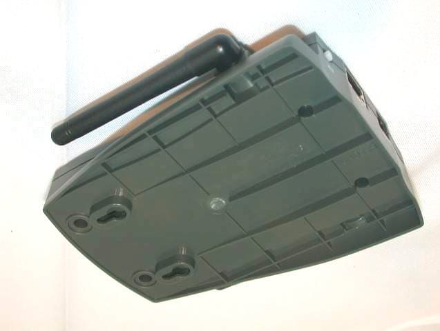
Click to zoom
Application Details
- Equipment Class
- DTS - Digital Transmission System
- Date of Grant
- Jul 02, 2003
- Application Purpose
- Original Equipment
- Date of Application
- Jul 02, 2003
- Equipment Note
- EZ Connect 2.4 GHz Wireless Ethernet Adapter
- Frequency Range
- 2412.00000000 - 2462.00000000
- Company
- Accton Technology Corp
- Country
- Taiwan
Documents & Files
Document Text
Text extracted from the exhibit documents filed with the FCC. Open a document above to read the original.
Users Manual
38 Tesla Irvine, CA 92618 Phone: (949) 679-8000 EZ Connect TM 2.4 GHz Wireless Ethernet Adapter User Guide From SMC’s EZ line of low-cost workgroup LAN solutions June 2003 Copyright Information furnished by SMC Networks, Inc. (SMC) is believed to be accurate and reliable. However, no responsibility is assumed by SMC for its use, nor for any infringements of patents or other rights of third parties which may result from its use. No license is granted by implication or otherwise under any patent or patent rights of SMC. SMC reserves the right to change specifications at any time without notice. Copyright © 2003 by SMC Networks, Inc. 38 Tesla Irvine, CA 92618 All rights reserved. Trademarks: SMC is a registered trademark; and EZ Connect is a trademark of SMC Networks, Inc. Other product and company names are trademarks or registered trademarks of their respective holders. i LIMITED WARRANTY Limited Warranty Statement: SMC Networks, Inc. (“SMC”) warrants its products to be free from defects in workmanship and materials, under normal use and service, for the applicable warranty term. All SMC products carry a standard 90-day limited warranty from the date of purchase from SMC or its Authorized Reseller. SMC may, at its own discretion, repair or replace any product not operating as warranted with a similar or functionally equivalent product, during the applicable warranty term. SMC will endeavor to repair or replace any product returned under warranty within 30 days of receipt of the product. The standard limited warranty can be upgraded to a Limited Lifetime* warranty by registering new products within 30 days of purchase from SMC or its Authorized Reseller. Registration can be accomplished via the enclosed product registration card or online via the SMC web site. Failure to register will not affect the standard limited warranty. The Limited Lifetime warranty covers a product during the Life of that Product, which is defined as the period of time during which the product is an “Active” SMC product. A product is considered to be “Active” while it is listed on the current SMC price list. As new technologies emerge, older technologies become obsolete and SMC will, at its discretion, replace an older product in its product line with one that incorporates these newer technologies. At that point, the obsolete product is discontinued and is no longer an “Active” SMC product. A list of discontinued products with their respective dates of discontinuance can be found at: http://www.smc.com/index.cfm?action=customer_service_warranty All products that are replaced become the property of SMC. Replacement products may be either new or reconditioned. Any replaced or repaired product carries either a 30-day limited warranty or the remainder of the initial warranty, whichever is longer. SMC is not responsible for any custom software or firmware, configuration information, or memory data of Customer contained in, stored on, or integrated with any products returned to SMC pursuant to any warranty. Products returned to SMC should have any customer-installed accessory or add-on components, such as expansion modules, removed prior to returning the product for replacement. SMC is not responsible for these items if they are returned with the product. Customers must contact SMC for a Return Material Authorization number prior to returning any product to SMC. Proof of purchase may be required. Any product returned to SMC without a valid Return Material Authorization (RMA) number clearly marked on the outside of the package will be returned to customer at customer's expense. For warranty claims within North America, please call our toll-free customer support number at (800) 762-4968. Customers are responsible for all shipping charges from their facility to SMC. SMC is responsible for return shipping charges from SMC to customer. LIMITED WARRANTY ii WARRANTIES EXCLUSIVE: IF AN SMC PRODUCT DOES NOT OPERATE AS WARRANTED ABOVE, CUSTOMER’S SOLE REMEDY SHALL BE REPAIR OR REPLACEMENT OF THE PRODUCT IN QUESTION, AT SMC’S OPTION. THE FOREGOING WARRANTIES AND REMEDIES ARE EXCLUSIVE AND ARE IN LIEU OF ALL OTHER WARRANTIES OR CONDITIONS, EXPRESS OR IMPLIED, EITHER IN FACT OR BY OPERATION OF LAW, STATUTORY OR OTHERWISE, INCLUDING WARRANTIES OR CONDITIONS OF MERCHANTABILITY AND FITNESS FOR A PARTICULAR PURPOSE. SMC NEITHER ASSUMES NOR AUTHORIZES ANY OTHER PERSON TO ASSUME FOR IT ANY OTHER LIABILITY IN CONNECTION WITH THE SALE, INSTALLATION, MAINTENANCE OR USE OF ITS PRODUCTS. SMC SHALL NOT BE LIABLE UNDER THIS WARRANTY IF ITS TESTING AND EXAMINATION DISCLOSE THE ALLEGED DEFECT IN THE PRODUCT DOES NOT EXIST OR WAS CAUSED BY CUSTOMER'S OR ANY THIRD PERSON'S MISUSE, NEGLECT, IMPROPER INSTALLATION OR TESTING, UNAUTHORIZED ATTEMPTS TO REPAIR, OR ANY OTHER CAUSE BEYOND THE RANGE OF THE INTENDED USE, OR BY ACCIDENT, FIRE, LIGHTNING, OR OTHER HAZARD. LIMITATION OF LIABILITY: IN NO EVENT, WHETHER BASED IN CONTRACT OR TORT (INCLUDING NEGLIGENCE), SHALL SMC BE LIABLE FOR INCIDENTAL, CONSEQUENTIAL, INDIRECT, SPECIAL, OR PUNITIVE DAMAGES OF ANY KIND, OR FOR LOSS OF REVENUE, LOSS OF BUSINESS, OR OTHER FINANCIAL LOSS ARISING OUT OF OR IN CONNECTION WITH THE SALE, INSTALLATION, MAINTENANCE, USE, PERFORMANCE, FAILURE, OR INTERRUPTION OF ITS PRODUCTS, EVEN IF SMC OR ITS AUTHORIZED RESELLER HAS BEEN ADVISED OF THE POSSIBILITY OF SUCH DAMAGES. SOME STATES DO NOT ALLOW THE EXCLUSION OF IMPLIED WARRANTIES OR THE LIMITATION OF INCIDENTAL OR CONSEQUENTIAL DAMAGES FOR CONSUMER PRODUCTS, SO THE ABOVE LIMITATIONS AND EXCLUSIONS MAY NOT APPLY TO YOU. THIS WARRANTY GIVES YOU SPECIFIC LEGAL RIGHTS, WHICH MAY VARY FROM STATE TO STATE. NOTHING IN THIS WARRANTY SHALL BE TAKEN TO AFFECT YOUR STATUTORY RIGHTS. * SMC will provide warranty service for one year following discontinuance from the active SMC price list. Under the limited lifetime warranty, internal and external power supplies, fans, and cables are covered by a standard one-year warranty from date of purchas…
Text truncated - open the document above for the full version.
Users Manual
NAVIGATING THE WEB BROWSER INTERFACE 19 Advanced Settings Operation Mode: This may be set to Access Point, Repeater or Ethernet Converter. These modes are described below: •Access Point – functions as a standard IEEE 802.11b access point •Repeater – repeats an access point’s signals to extend the acess points coverage •Ethernet Converter – provides a wireless connection to an access point via an RJ-45 connection to devices such as Microsoft Xbox and Ethernet ready embedded devices SYSTEM CONFIGURATION 20 The parameters that follow may be configured in any of the three modes descibed above but the user is advised to leave them at their default settings. Transmission Rate: Set the data rate transmitted from the Wireless Access Point. The lower the data rate, the longer the transmission distance. (Default: Fully Automatic.) RTS Threshold: Set the RTS (Request to Send) frame length. You may configure the access point to initiate an RTS frame. If the packet size is smaller than the preset RTS threshold size, the RTS/CTS mechanism will NOT be enabled The access point sends Request to Send (RTS) frames to a particular receiving station to negotiate the sending of a data frame. After receiving an RTS, the station sends a CTS (Clear to Send) frame to acknowledge the right of the sending station to send data frames. The access points contending for the medium may not be aware of each other. The RTS/CTS mechanism can solve this “Hidden Node Problem.” (Default: 2347) Fragmentation Threshold: The Fragmentation Threshold can be set between 256 and 2,346. If the packet size is smaller than the preset Fragment size, the packet will not be segmented. Fragmentation of the PDUs (Package Data Unit) can increase the reliability of transmissions because it increases the probability of a successful transmission due to smaller frame size. If there is significant interference present, or collisions due to high network utilization, try setting the fragment size to send smaller fragments. This will enable the retransmission of smaller frames much faster. However, it is more efficient to set the fragment size larger if very little or no interference is present because it requires overhead to send multiple frames. (Default: 2346) NAVIGATING THE WEB BROWSER INTERFACE 21 Basic Rate: The highest rate specified is the rate the Wireless Access Point will use when transmitting broadcast/multicast and management frames. (Default: 1, 2 Mbps.) Preamble Type: The access points and client card drivers have a radio setting for RF Preamble. Enabling it can boost your throughput. Preamble Type offers a drop-down list with two options: Long or Short. If you are not sure whether all the clients and access point radios in your wireless network support the Short RF preamble, then leave this setting on Long (default). Transmit Power: Set the signal strength transmitted from the access point. The longer the transmission distance, the higher the transmission power required. (Default: Super) Selections - Weak, Medium, Normal, High and Super SYSTEM CONFIGURATION 22 Filter The MAC Filtering feature of the SMC2671W allows you to control access to your network clients based on the MAC (Media Access Control) Address of the client machine. This ID is unique to each network adapter. If the MAC address is listed in the table, that client machine will not have access to the network. NAVIGATING THE WEB BROWSER INTERFACE 23 Tools Use the Tools menu to backup the current configuration, restore a previously saved configuration, restore factory settings, update firmware, and reset the SMC2671W. Configuration Tools •Backup Settings – saves the SMC2671W’s configuration to a file. •Restore Settings – restores settings from a saved backup configuration file. •Restore to Factory Defaults – restores the SMC2671W settings back to the factory default original. SYSTEM CONFIGURATION 24 Firmware Upgrade Use this screen to update the firmware or user interface to the latest versions. Download the upgrade file from the web site and save it to your hard drive. In the Upgrade Target field, choose Firmware. Then click Browse to look for the previously downloaded file. Click APPLY. Check the Status page Information section to confirm that the upgrade process was successful. NAVIGATING THE WEB BROWSER INTERFACE 25 Reset Click APPLY to reset the SMC2617W. The reset will be complete when the power LED stops blinking. SYSTEM CONFIGURATION 26 Status The Status screen displays WAN/LAN connection status, firmware, and hardware version numbers of the SMC2671W. Statistics The Statistics page displays transmit and receive statistics for all associated stations. UTILITY INSTALLATION (98/ME/NT/2000) 27 Utility Installation (98/Me/NT/2000) 1. Insert the SMC2671W utility disk into the floppy drive on your PC, and then enter the following command: A:\setup. Follow the on-screen instructions to install the utility program. Using the AP Management Utility 1. Click Start/Programs/SMC/EZ Connect Wireless AP Manager. The program will automatically scan for all access points on the network. If you want to subsequently detect all access points on the network, click Command and then select Scan AP from the menu. 2. From the list of detected SMC2671Ws, double-click on the unit you wish to configure. A dialogue box will prompt you for the login password. SYSTEM CONFIGURATION 28 3. Enter the default password: Private. 4. Click the Command main menu item. 5. Select Configure AP In the Command main menu. Configure AP The Configure AP screen displays the AP status and settings. The screen is divided into two sections. The first section is read-only. BSS ID – Media Access Control address. Regulation Domain - Countries have different regulations regarding the use of radio frequencies. WEP – WEP (Wired Equivalent Privacy) Enabled/Disabled status. Associated Stations – Number of wireless clients. UTILITY INSTALLATION (98/ME/NT/2000) 29 Firmware Version – Current firmware version. SSID – Clients in yo…
Text truncated - open the document above for the full version.
Cover Letter(s)
[email protected] www.adt.com.tw ADVANCE DATA TECHNOLOGY CORPORATION FEDERAL COMMUNICATIONS COMMISSION DECLARATION OF CONFORMITY (DoC) FOR THE FOLLOWING EQUIPMENT: PRODUCT NAME :EZ Connect 2.4GHz Wireless Ethernet Adapter MODEL NO : SMC2671W; WA3001B-17 TRADE NAME : SMC; Accton IS HEREWITH CONFIRMED AND FOUND TO COMPLY WITH THE REQUIREMENTS OF CFR 47 PART 15 REGULATION. THE RESULTS OF ELECTROMAGNETIC EMISSION EVALUATION ARE SHOWN IN THE REPORT NO : RF920407H03 THIS DEVICE COMPLIES WITH PART 15 OF THE FCC RULES. OPERATION IS SUBJECT TO THE FOLLOWING TWO CONDITIONS: (1) THIS DEVICE MAY NOT CAUSE HARMFUL INTERFERENCE AND, (2) THIS DEVICE MUST ACCEPT ANY INTERFERENCE RECEIVED, INCLUDING INTERFERENCE THAT MAY CAUSE UNDESIRED OPERATION. THE FOLLOWING LOCAL MANUFACTURER/IMPORTER IS RESPONSIBLE FOR THIS DECLARATION Manufacturer USA Local Representative Company name: Accton Technology Corporation Company name: SMC Networks Address: No.1, Creation Rd. III, Science-based Industrial Park, Hsinchu, Taiwan, R.O.C. Address: 38 Tesla Irvine, CA 92618 Contact Person: Hsoang-Shen Chen Contact Person: Kelaine Hamilton Title: Section Manager Title: Product Line Manager Tel/Fax: Tel:886-3-5770270 Fax:886-3-5783839 Tel/Fax: Tel:949-981-5912 Fax:949-679-1481
External Photos
Page 1 CONSTRUCTION PHOTOS OF EUT
ID Label/Location Info
3 0 . 0 58.0
ID Label/Location Info
(Fig. 1) FCC ID: HEDWA3001B17 FCC LABEL LOCATION The label will be permanently affixed at a conspicuous location on the device. Label
Internal Photos
Page 1 CONSTRUCTION PHOTOS OF EUT Page 2 Page 3 Adapter Model No.: DSA-0051-03 Page 4 Page 5 Page 6 Adapter Model No.: DSA-0051-03 FEU Page 7 Page 8
Operational Description
FCC ID: HEDWA3001B17 Report No.: 920407H03 ADT No.: 920407H03 Operational Description The transmitter of the EUT (EZ Connect 2.4GHz Wireless Ethernet Adapter) is powered by power adapter. The antenna used in this product is Fixable Dipole Antenna without connector. Under normal use condition, the user has to keep at least 20cm separation distance between radiator and the body of the user. The other instruction, please have a look at the users manual. DSSS Information This device is Direct Sequence Spread Spectrum, the data is mixed by pseudorandom code which is an orthogonal code. The mixed data is digital modulated by DBPSK and DQPSK technique depends on the data rates. The CCK coding is applied for increasing the data rate, and also the processing gain will be increased. The bit rates are 1,2,5.5,11Mbps.
RF Exposure Info
FCC ID: HEDWA3001B17 Report No.: 920407H03 ADT No.: 920407H03 RF EXPOSURE REPORT REPORT NO.: RF920407H03 MODEL NO.: SMC2671W, WA3001B-17, GW-AP11X ACCORDING: FCC Guidelines for Human Exposure IEEE C95.1 APPLICANT: Accton Technology Corporation ADDRESS: No.1, Creation Rd. III, Science-based Industrial Park, Hsinchu, Taiwan, R.O.C. ISSUED BY: Advance Data Technology Corporation LAB LOCATION: No. 81-1, Lu Liao Keng, 9 Ling, Wu Lung Tsuen, Chiung Lin Hsiang, Hsin Chu Hsien, Taiwan, R.O.C. Lab Code: 200376-0 FCC ID: HEDWA3001B17 Report No.: 920407H03 ADT No.: 920407H03 RF Exposure Measurement 1. Introduction In this document, we try to prove the safety of radiation harmfulness to the human body for our product. The limit for Maximum Permissible Exposure (MPE) specified in FCC 1.1310 is followed. The Gain of the antenna used in this product is measured in a Fully Anechoic Chamber (FAC) calibrated for antenna measurement in ADT, and also the maximum total power input to the antenna is measured. Through the Friis transmission formula and the maximum gain of the antenna, we can calculate the distance, away from the product, where the limit of MPE is reached. Although the Friis transmission formula is a far field assumption, the calculated result of that is an over-prediction for near field power density. We will take that as the worst case to specify the safety range. 2. RF Exposure Limit According to FCC 1.1310: The criteria listed in the following table shall be used to evaluate the environmental impact of human exposure to radio-frequency (RF) radiation as specified in 1.1307(b) LIMITS FOR MAXIMUM PERMISSIBLE EXPOSURE (MPE) Frequency Range (MHz) Electric Field Strength (V/m) Magnetic Field Strength (A/m) Power Density (mW/cm 2 ) Average Time (minutes) (A)Limits For Occupational / Control Exposures 300-1500......F/3006 1500-100,000......56 (B)Limits For General Population / Uncontrolled Exposure 300-1500......F/15006 1500-100,000......1.030 F = Frequency in MHz FCC ID: HEDWA3001B17 Report No.: 920407H03 ADT No.: 920407H03 3. Friis Formula Friis transmission formula : Pd = (Pout*G) / (4*pi*r 2 ) where Pd = power density in mW/cm 2 Pout = output power to antenna in mW G = gain of antenna in linear scale Pi = 3.1416 R = distance between observation point and center of the radiator in cm Pd is the limit of MPE, 1 mW/cm 2 . If we know the maximum Gain of the antenna and the total power input to the antenna, through the calculation, we will know the MPE value at distance 20cm. Ref. : David K. Cheng, Field and Wave Electromagnetics, Second Edition, Page 640, Eq. (11-133). 4 EUT Operating condition The software provided by Manufacturer enabled the EUT to transmit and receive data at lowest, middle and highest channel individually. 5 Climate Condition The temperature and related humidity: 20 deg. C and 63 % RH 6. Classification This device is not fixed inside the host equipment, it is connected with host through wire. So it is easy to be re-located in the place where at least 20 cm far away from the body of the user. Warning statement to the user for keeping at least 20cm or more separation distance with the antenna should be included in users manual. So, this device is classified as Mobile Device. FCC ID: HEDWA3001B17 Report No.: 920407H03 ADT No.: 920407H03 7 Test Results 7.1 Antenna Gain The maximum Gain measured in Fully Anechoic Chamber are 2dBi or 1.58 (numeric). 7.2 Output Power Into Antenna & RF Exposure value at distance 20cm: Channel Channel Frequency (MHz) Output Power to Antenna (mW) Power Density (mW/cm 2 ) Limit of Power Density (mW/cm 2 ) 1241231.0460.0097891.0 6243734.0410.0107331.0 11246235.4810.0111871.0
Test Report
FCC ID: HEDWA3001B17 Report No.: RF920407H031Issued: Jun. 27, 2003 ADT No. 920407H03 FCC TEST REPORT REPORT NO.: RF920407H03 MODEL NO.: SMC2671W, WA3001B-17, GW-AP11X RECEIVED: Apr. 07, 2003 TESTED: Apr. 10 to Jun. 26, 2003 APPLICANT: Accton Technology Corporation ADDRESS: No.1, Creation Rd. III, Science-based Industrial Park, Hsinchu, Taiwan, R.O.C. ISSUED BY: Advance Data Technology Corporation LAB LOCATION: No. 81-1, Lu Liao Keng, 9 Ling, Wu Lung Tsuen, Chiung Lin Hsiang, Hsin Chu Hsien, Taiwan, R.O.C. This test report consists of 50 pages in total. It may be duplicated completely for legal use with the approval of the applicant. It should not be reproduced except in full, without the written approval of our laboratory. The client should not use it to claim product endorsement by NVLAP or any government agencies. The test results in the report only apply to the tested sample. Lab Code: 200376-0 FCC ID: HEDWA3001B17 Report No.: RF920407H032Issued: Jun. 27, 2003 ADT No. 920407H03 Table of Contents 1CERTIFICATION......................................................................................................4 2SUMMARY OF TEST RESULTS...........................................................................5 3GENERAL INFORMATION....................................................................................6 3.1GENERAL DESCRIPTION OF EUT.....................................................................6 3.2DESCRIPTION OF TEST MODES.......................................................................8 3.3GENERAL DESCRIPTION OF APPLIED STANDARDS..................................8 3.4DESCRIPTION OF SUPPORT UNITS.................................................................9 4TEST TYPES AND RESULTS.............................................................................10 4.1CONDUCTED EMISSION MEASUREMENT....................................................10 4.1.1TEST INSTRUMENTS.............................................................................................10 4.1.2TEST PROCEDURES..............................................................................................11 4.1.3DEVIATION FROM TEST STANDARD....................................................................11 4.1.4TEST SETUP...........................................................................................................12 4.1.5EUT OPERATING CONDITIONS............................................................................13 4.1.6TEST RESULTS.......................................................................................................14 4.2RADIATED EMISSION MEASUREMENT.........................................................20 4.2.1LIMITS OF RADIATED EMISSION MEASUREMENT............................................20 4.2.2TEST INSTRUMENTS.............................................................................................21 4.2.3TEST PROCEDURES.............................................................................................22 4.2.4DEVIATION FROM TEST STANDARD...................................................................22 4.2.5TEST SETUP...........................................................................................................23 4.2.6EUT OPERATING CONDITIONS............................................................................23 4.2.7TEST RESULTS.......................................................................................................24 4.36dB BANDWIDTH MEASUREMENT.................................................................28 4.3.1LIMITS OF 6dB BANDWIDTH MEASUREMENT....................................................28 4.3.2TEST INSTRUMENTS.............................................................................................28 4.3.3TEST PROCEDURE................................................................................................29 4.3.4DEVIATION FROM TEST STANDARD...................................................................29 4.3.5TEST SETUP...........................................................................................................29 4.3.6EUT OPERATING CONDITIONS............................................................................29 4.3.7TEST RESULTS.......................................................................................................30 4.4MAXIMUM PEAK OUTPUT POWER.................................................................34 4.4.1LIMITS OF MAXIMUM PEAK OUTPUT POWER MEASUREMENT......................34 4.4.2INSTRUMENTS........................................................................................................34 4.4.3TEST PROCEDURES.............................................................................................35 4.4.4DEVIATION FROM TEST STANDARD...................................................................35 4.4.5TEST SETUP...........................................................................................................35 FCC ID: HEDWA3001B17 Report No.: RF920407H033Issued: Jun. 27, 2003 ADT No. 920407H03 4.4.6EUT OPERATING CONDITIONS............................................................................35 4.4.7TEST RESULTS.......................................................................................................36 4.4.8LIMITS OF POWER SPECTRAL DENSITY MEASUREMENT...............................37 4.4.9TEST INSTRUMENTS.............................................................................................37 4.4.10TEST PROCEDURE................................................................................................38 4.4.11DEVIATION FROM TEST STANDARD...................................................................38 4.4.12TEST SETUP...........................................................................................................38 4.4.13EUT OPERATING CONDITION...............................................................................38 4.4.14TEST RESULTS....…
Text truncated - open the document above for the full version.
Test Report
Report No. 920407H03 ADT No. 920407H03 1 The Measurement of Conducted Spurious Emissions CONDUCTED SPURIOUS EMISSIONS MEASUREMENT 1. LIMITS OF CONDUCTED SPURIOUS EMISSIONS EASUREMENT Below 20dB of the highest emission level of operating band (in 100KHz Resolution Bandwidth, see Section 15.247(c)). Emissions which fall in the restricted bands, as defined in Section 15.205(a), must also comply with the limits specified in Section 15.209(a) (see Section 15.205(c)). 2. TEST INSTRUMENTS Description & Manufacturer Model No. Serial No. Calibrated Until R&S SPECTRUM ANALYZER FSP 1093.4495.30 Dec. 19, 2003 NOTE: 1.The measurement uncertainty is less than +/- 2.6dB, which is calculated as per the NAMAS document NIS81. 2.The calibration interval of the above test instruments is 12 months and the calibrations are traceable to NML/ROC and NIST/USA. 3. TEST PROCEDURE The transmitter output was connected to the spectrum analyzer via a low lose cable. Set both RBW and VBW of spectrum analyzer to 100 kHz with suitable frequency span including 100 kHz bandwidth from band edge. The band edges was measured and recorded. Report No. 920407H03 ADT No. 920407H03 2 4. TEST SETUP 5. EUT OPERATING CONDITIONS The software provided by client to enable the EUT under transmission condition continuously at lowest, middle and highest channel frequencies individually. EUT SPECTRUM ANALYZER Report No. 920407H03 ADT No. 920407H03 3 TEST RESULTS The spectrum plots are attached on the following 6 pages. It shows compliance with the requirement in part 15.247(C),.15.205 and 15.209. Report No. 920407H03 ADT No. 920407H03 4 Ch1 Report No. 920407H03 ADT No. 920407H03 5 Ch1 Report No. 920407H03 ADT No. 920407H03 6 Ch6 Report No. 920407H03 ADT No. 920407H03 7 Ch6 Report No. 920407H03 ADT No. 920407H03 8 Ch11 Report No. 920407H03 ADT No. 920407H03 9 Ch11
Test Setup Photos
FCC ID: HEDWA3001B17 Report No.: RF920407H0348Issued: Jun. 27, 2003 ADT No. 920407H03 5 PHOTOGRAPHS OF THE TEST CONFIGURATION CONDUCTED EMISSION TEST FCC ID: HEDWA3001B17 Report No.: RF920407H0349Issued: Jun. 27, 2003 ADT No. 920407H03 RADIATED EMISSION TEST
Contact Information
Applicant
Abby Wei(Manager)
Technical Contact
Advance Data Technology CorporationEric Lin
[email protected]+8863593 5343
81-1 Luliaoken, 9th Lin, Wulung Tsuen Chiunglin · Hsinchu · Taiwan
Test Firm
Bureau Veritas CPS (H.K.) Ltd. Taoyuan BranchRichard Chen
Technical Specifications
| # | Rule Parts | Frequency Range | Power Output |
|---|---|---|---|
| 1 | 15C | 2.41 GHz - 2.46 GHz | 35.50 mW |
Other Applications from Accton Technology Corp

HEDEAP115
Jan 27, 2026Wi-Fi 7 AP
Equipment Class
NII - Unlicensed National Information Infrastructure TX
HEDEAP112
Oct 13, 2024Wi-Fi 6 IoT Gateway
Equipment Class
DTS - Digital Transmission System
HEDEAP111
Mar 17, 2024Wi-Fi 6 Access Point
Equipment Class
DTS - Digital Transmission System
HEDOAP101E
Oct 24, 2023Outdoor Access Point
Equipment Class
DTS - Digital Transmission System
HEDEAP104
Dec 14, 2022Indoor Wall Plate WiFi 6 Access Point
Equipment Class
DTS - Digital Transmission System