HEDWA3101ACCWLAN Access Point
Accton Technology Corp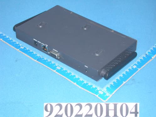
Click to zoom
Application Details
- Equipment Class
- DTS - Digital Transmission System
- Date of Grant
- May 11, 2003
- Application Purpose
- Original Equipment
- Date of Application
- May 11, 2003
- Equipment Note
- WLAN Access Point
- Frequency Range
- 2412.00000000 - 2462.00000000
- Company
- Accton Technology Corp
- Country
- Taiwan
Documents & Files
Document Text
Text extracted from the exhibit documents filed with the FCC. Open a document above to read the original.
Users Manual
4/1/03 Accton Draft—CONFIDENTIAL Aruba 50 Wireless Access Point Installation Guide TM 180 Great Oaks Blvd. Ste B San Jose, California 95119 Net www.arubanetworks.com Tel 408.227.4500 Fax 408.227.4550 4/1/03 Accton Draft—CONFIDENTIAL ii Aruba 50Part 0500007A Installation GuideMay 2003 Copyright Copyright © 2003 Aruba Wireless Networks, Inc. All rights reserved. Specifications in this manual are subject to change without notice. Originated in the USA. Trademarks AirOS, Aruba 50, and Aruba 5000 are trademarks of Aruba Wireless Networks in the United States and certain other countries. The K & Lock design is a registered trademark of the Kensington Technology Group in the United States and certain other countries. Any other trademarks appearing in this manual are owned by their respective companies. Aruba 50 iii Installation Guide 4/1/03 Accton Draft—CONFIDENTIAL Compliance FCC - Class B This equipment has been tested and found to comply with the limits for a Class B digital device, pursuant to Part 15 of the FCC Rules. These limits are designed to provide reasonable protection against harmful interference in a residential installation. This equipment generates, uses and can radiate radio frequency energy and, if not installed and used in accordance with instructions, may cause harmful interference to radio communications. However, there is no guarantee that the interference will not occur in a particular installation. If this equipment does cause harmful interference to radio or television reception, which can be determined by turning the equipment off and on, the user is encouraged to try to correct the interfer- ence by one or more of the following measures: zReorient the receiving antenna zIncrease the separation between the equipment and receiver zConnect the equipment into an outlet on a circuit different from that to which the receiver is con- nected zConsult the dealer or an experienced radio/TV technician for help FCC Caution: To assure continued compliance, use only shielded interface cables when connecting to computer or peripheral devices. Any changes or modifications not expressly approved by the party respon- sible for compliance could void the user’s authority to operate this equipment. This device complies with Part 15 of the FCC Rules. Operation is subject to the following two conditions: (1) This device may not cause harmful interference, and (2) this device must accept any interference received, including interference that may cause undesired operation. CAUTION STATEMENT: FCC RF Radiation Exposure Statement This equipment complies with FCC RF radiation exposure limits set forth for an uncontrolled environ- ment. This equipment should be installed and operated with a minimum distance of 20 centimeters (8 inches) between the radiator and your body. This transmitter must not be co-located or operating in con- junction with any other antenna or transmitter. Industry Canada - Class B This digital apparatus does not exceed the Class B limits for radio noise emissions from digital apparatus as set out in the interference-causing equipment standard entitled “Digital Apparatus,” ICES-003 of the Department of Communications. Cet appareil numérique respecte les limites de bruits radioélectriques applicables aux appareils numériques de Classe B prescrites dans la norme sur le matériel brouilleur: “Appareils Numériques,” NMB-003 édictée par le ministère des Communications. 4/1/03 Accton Draft—CONFIDENTIAL iv Aruba 50Part 0500007A Installation GuideMay 2003 Contents v 4/1/03 Accton Draft—CONFIDENTIAL Contents Preface. . . . . . . . . . . . . . . . . . . . . . vii Related Documents . . . . . . . . . . . . . . . . . . vii Text Conventions . . . . . . . . . . . . . . . . . . viii Contacting Aruba Wireless Networks . . . . . . . . . . ix Chapter 1 Introduction . . . . . . . . . . . . . . . . . . . 1 Product Features . . . . . . . . . . . . . . . . . . . . 1 Ethernet Compatibility . . . . . . . . . . . . . . . 2 Radio Characteristics . . . . . . . . . . . . . . . . 2 Power Over Ethernet . . . . . . . . . . . . . . . . 2 Physical Description . . . . . . . . . . . . . . . . . . 3 Package Checklist . . . . . . . . . . . . . . . . . 3 Top Panel . . . . . . . . . . . . . . . . . . . . . 3 Rear Panel . . . . . . . . . . . . . . . . . . . . . 5 Chapter 2 Setup & Installation . . . . . . . . . . . . . 7 Requirements . . . . . . . . . . . . . . . . . . . . . 7 Select a Network Topology . . . . . . . . . . . . . . . 8 Perform Initial Setup . . . . . . . . . . . . . . . . . . 10 Direct SPOE to the Aruba WLAN Switch . . . . . 10 Direct Terminal Connection . . . . . . . . . . . . 11 Configure the Aruba 50 . . . . . . . . . . . . . . . 12 Mount the Aruba 50 . . . . . . . . . . . . . . . . . . 14 Free-Standing Placement . . . . . . . . . . . . . . 15 Using the Mounting Kit . . . . . . . . . . . . . . 15 4/1/03 Accton Draft—CONFIDENTIAL vi Aruba 50Part 0500007A Installation GuideMay 2003 Connect Required Cables. . . . . . . . . . . . . . . . 18 Direct SPOE to the Aruba WLAN Switch . . . . . 18 LAN or POE Connection . . . . . . . . . . . . . . 19 Appendix A Troubleshooting . . . . . . . . . . . . . . . 21 Appendix B Port Specifications. . . . . . . . . . . . . 23 Console Port . . . . . . . . . . . . . . . . . . . . . . 23 FE Port . . . . . . . . . . . . . . . . . . . . . . . . 24 SPOE Adapter . . . . . . . . . . . . . . . . . . . . . 25 Appendix C Product Specifications. . . . . . . . . . 27 Preface vii 4/1/03 Accton Draft—CONFIDENTIAL Preface The preface includes the following information: zA list of related documentation for further reading zA key to the various text conventions used throughout this manual zAruba Wireless Networks support and service information Related Documents The following items are part of the complete documentation for the Aruba system: zAruba 50 Installation Guide (Part No. 050007A, May 2003) zAruba 5000 Installation Guide (Part No. 0500001A, May 2003) zAruba AirOS v1.0 User’s Guide…
Text truncated - open the document above for the full version.
Users Manual
Setup & Installation 11 Chapter 2 4/3/03 Accton Draft—CONFIDENTIAL When prompted, log in to the Aruba WLAN Switch as the administrator: user: admin password: <administrator password (not displayed)> This will present you with the Aruba WLAN Switch SOE console prompt (soe>). Specify the physical Aruba WLAN Switch port to which the new Aruba 50 is con- nected: soe> connect <slot number>/<port number> This will present you with the Aruba 50 console prompt (#). Once connected to the console, follow the instruction on page 12 to configure Aruba 50. Direct Terminal Connection Use this procedure when connecting the Aruba 50 through the LAN or to a non-SPOE net- work port on the Aruba WLAN Switch. Under these topologies, a direct terminal connection is required for initial setup. N OTE—If connecting the Aruba 50 directly to a SPOE network port on the Aruba WLAN Switch, see the instructions on page 10. Set up your local terminal. This procedure requires a terminal or computer running terminal emulation software with the following settings: Connect the terminal directly to the Aruba 50. Use a standard serial cable to connect the Aruba 50 console port to a serial port on your termi- nal (see Appendix B for port specification). Establish console communication. Press <Enter> a few times to establish communication between the terminal and the Aruba 50. You will be presented the Aruba 50 console prompt (#). Once connected to the Aruba 50 console, follow the instruction on page 12 to configure the device. TABLE2-1Console Terminal Settings Baud RateData BitsParityStop BitsFlow Control 96008None1None 4 5 1 2 3 4/3/03 Accton Draft—CONFIDENTIAL 12 Aruba 50Part 0500007A Installation GuideMay 2003 Configure the Aruba 50 From the Aruba 50 console, access the boot prompt. Reboot the Aruba 50 and then immediately (within three seconds as the device is booting) press any key to interrupt the process: # boot <Any key (while booting)> This will present you with the Aruba 50 boot prompt (apboot>). Set the intended location for the Aruba 50: apboot> setenv location <building number>.<floor number>.<device number> If you performed the recommended site survey using the Aruba WLAN Switch’s built-in planning tools, the location data for all access points and air monitors can be found on the tool’s deployment screen (see the Aruba AirOS Software Guide). If you plan to manually generate the location data, record the following information for each access point and air monitor. It will be required when configuring the Aruba WLAN Switch. Building NumberA unique number (1-255) is required for each building in your campus. Floor NumberWithin any building, a unique number (1-255) is required for each floor. Device NumberWithin any floor, a unique number (1-65536) is required for each access point or air monitor. Device Description Note the intended function of the device (access point or dedicated air monitor) and a brief description of its service location. X, Y CoordinatesFor each access point and air monitor, measure its X and Y position (in feet) relative to the bottom-left corner of the building plan as seen from overhead. For example: Use the same fixed point and orientation for all floors in a building. 1 2 Setup & Installation 13 Chapter 2 4/3/03 Accton Draft—CONFIDENTIAL Specify host information, if necessary. The Aruba 50 uses the default host name aruba-master to find the host Aruba WLAN Switch. This assumes that your DNS has been configured to resolve aruba-master to the master Aruba WLAN Switch IP address. zIf you are not using DNS, you must manually configure the Aruba 50 with the IP address of the master Aruba WLAN Switch: apboot> setenv serverip <switch IP address> zIf you are using DNS but wish to specify a different host name, use the following com- mands: apboot> setenv master <switch host name> apboot> setenv serverip <switch host name> Save the configuration and reboot the Aruba 50. apboot> save apboot> boot Once the Aruba 50 boots, disconnect it and mount it in its intended service location (see instructions on page 14). 3 4 4/3/03 Accton Draft—CONFIDENTIAL 14 Aruba 50Part 0500007A Installation GuideMay 2003 Mount the Aruba 50 When initial setup is complete, mount the Aruba 50 in its intended service location. Select a location as close as possible to the center of the intended coverage area. If necessary, use the Aruba WLAN Switch’s built-in site survey software to determine the optimum loca- tions for your access points and air monitors (see your Aruba AirOS Software Guide). The service location should be free from obstructions or obvious sources of interference. Nor- mally, the higher you place an access point or air monitor, the better its performance. The Aruba 50 can be mounted in the following ways: FIGURE2-2 Aruba 50 Mounting Options Flat on a table or shelf (with the LEDs on top) either free-standing or using the included mounting kit Upright on a wall (with the port connectors on top) using the included mounting kit Suspended from above (with the LEDs on bottom) using the included mounting kit 1 2 3 CAUTION—For safety purposes, do not mount the Aruba 50 sideways (with the air vents on top and bottom). Setup & Installation 15 Chapter 2 4/3/03 Accton Draft—CONFIDENTIAL Free-Standing Placement To place the Aruba 50 on a flat table or shelf, first attach the included non-skid foot-pads to the bottom of the chassis. Using the Mounting Kit Use the included mounting kit to attach the Aruba 50 to a wall, shelf, or ceiling. N OTE—Do not attach the rubber foot-pads to the Aruba 50 when using the mounting kit. Attach the mounting cradle to a solid mounting surface. Place the flat side of the cradle against the mounting surface. If attaching the cradle to a wall, orient it so that the cable tie anchors are positioned at the top. If attaching the cradle to a table, shelf, or ceiling, orient the cable tie anchors toward the cable route. CAUTION—Do not place the Aruba 50 in any place where it could fall on peopl…
Text truncated - open the document above for the full version.
Attestation Statements
[email protected] www.adt.com.tw ADVANCE DATA TECHNOLOGY CORPORATION FEDERAL COMMUNICATIONS COMMISSION DECLARATION OF CONFORMITY (DoC) FOR THE FOLLOWING EQUIPMENT: PRODUCT NAME : WLAN Access Point MODEL NO : MP-50-B ; WA3101 TRADE NAME : ARUBA Wireless Ne IS HEREWITH CONFIRMED AND FOUND TO COMPLY WITH THE REQUIREMENTS OF CFR 47 PART 15 REGULATION. THE RESULTS OF ELECTROMAGNETIC EMISSION EVALUATION ARE SHOWN IN THE REPORT NO : RF920225H03 THIS DEVICE COMPLIES WITH PART 15 OF THE FCC RULES. OPERATION IS SUBJECT TO THE FOLLOWING TWO CONDITIONS: (1) THIS DEVICE MAY NOT CAUSE HARMFUL INTERFERENCE AND, (2) THIS DEVICE MUST ACCEPT ANY INTERFERENCE RECEIVED, INCLUDING INTERFERENCE THAT MAY CAUSE UNDESIRED OPERATION. THE FOLLOWING LOCAL MANUFACTURER/IMPORTER IS RESPONSIBLE FOR THIS DECLARATION ManufacturerUSA Local Representative Company name: Accton Technology Corporation Company name: Aruba Wireless Networks Inc. Address: No.1, Creation Rd. III, Science-based Industrial Park, Hsinchu, Taiwan, R.O.C. Address: 180 Great Oaks Blvd. San Jose, CA, 95124, USA Contact Person: Hsoang-Shen Chen Contact Person: Loren Vorreiter Title: Section Manager Title: Mechanical Engineer Tel/Fax: Tel:886-3-5770270 Fax:886-3-5783839 Tel/Fax: Tel: 408-754-3048 Fax: 408-227-4550
Block Diagram
Operating Channels: IEEE 802.11 compliant Frequency Band: USA – FCC 2412~2462MHz (Ch1~Ch11) Canada – IC 2412~2462MHz (Ch1~Ch11) .NEW Zealand 2412~2462MHz (Ch1~Ch11) Europe – ETSI 2412~2472MHz (Ch1~Ch13) Frequency : 32 MHz
Block Diagram
WN3101A 374MH Z 2074MH Z
External Photos
Page 1 CONSTRUCTION PHOTOS OF EUT Page 2
ID Label/Location Info
(Fig. 1) FCC ID: FCC LABEL LOCATION The label will be permanently affixed at a conspicuous location on the device. Label
ID Label/Location Info
Accton Technology Corporation. TITLE: LABEL,AGENCY,ACCESS POINT DWG NO: 4000012REV AC . ARUBA WIRELESS NETWORKS INC. This device complies with Part 15 of the FCC Rules. Operation is subject to the following two conditions: (1) This device may not cause harmful interference, and (2) This device must accept any interference received, including interference that may cause undesired operation. MODEL #:WA3101 0560 FCC ID:HEDWA3101ACC IC:3857A-WA3101AC Complies with RSS-210ICES-003 CLASS B INPUT VOLTAGE RANGE 3.3V dc ,3A Made in xxxxxxx XXX 146xxxxxxxxxE r01xx MFG Country (Ariel Narrow, Point 4) MFG Factory (Ariel Narrow, Point 4) Vendor ID (Ariel Narrow, Point 4) 60.0 mm 42.0 mm Material: metalized + Glossy PP thickness: .2 mm Adhesive: UL Approved - Acrylic Text color: Black MFG Country Code SVA Accton (Shen Zhen) ---GZ Accton (Shen Zhen)---------AC MFG Country Decided by import and export country Vendor ID Decided by Vendor ID Number R 2.5 4 places !
Internal Photos
Page 1 CONSTRUCTION PHOTOS OF EUT Page 2 Page 3 Page 4 Page 5 Page 6 Page 7 Page 8 Page 9 Page 10
RF Exposure Info
FCC ID: HEDWA3101ACC Report No.: 920220H04A ADT No.: 920225H03 RF EXPOSURE REPORT REPORT NO.: RF920220H04A MODEL NO.: MP-50-B, WA3101 ACCORDING: FCC Guidelines for Human Exposure IEEE C95.1 APPLICANT: Accton Technology Corporation ADDRESS: No.1, Creation Rd. III, Science-based Industrial Park, Hsinchu, Taiwan, R.O.C ISSUED BY: Advance Data Technology Corporation LAB LOCATION: No. 81-1, Lu Liao Keng, 9 Ling, Wu Lung Tsuen, Chiung Lin Hsiang, Hsin Chu Hsien, Taiwan, R.O.C. Lab Code: 200376-0 FCC ID: HEDWA3101ACC Report No.: 920220H04A ADT No.: 920225H03 RF Exposure Measurement 1. Introduction In this document, we try to prove the safety of radiation harmfulness to the human body for our product. The limit for Maximum Permissible Exposure (MPE) specified in FCC 1.1310 is followed. The Gain of the antenna used in this product is measured in a Fully Anechoic Chamber (FAC) calibrated for antenna measurement in ADT, and also the maximum total power input to the antenna is measured. Through the Friis transmission formula and the maximum gain of the antenna, we can calculate the distance, away from the product, where the limit of MPE is reached. Although the Friis transmission formula is a far field assumption, the calculated result of that is an over-prediction for near field power density. We will take that as the worst case to specify the safety range. 2. RF Exposure Limit According to FCC 1.1310: The criteria listed in the following table shall be used to evaluate the environmental impact of human exposure to radio-frequency (RF) radiation as specified in 1.1307(b) LIMITS FOR MAXIMUM PERMISSIBLE EXPOSURE (MPE) Frequency Range (MHz) Electric Field Strength (V/m) Magnetic Field Strength (A/m) Power Density (mW/cm 2 ) Average Time (minutes) (A)Limits For Occupational / Control Exposures 300-1500......F/3006 1500-100,000......56 (B)Limits For General Population / Uncontrolled Exposure 300-1500......F/15006 1500-100,000......1.030 F = Frequency in MHz FCC ID: HEDWA3101ACC Report No.: 920220H04A ADT No.: 920225H03 3. Friis Formula Friis transmission formula : Pd = (Pout*G) / (4*pi*r 2 ) where Pd = power density in mW/cm 2 Pout = output power to antenna in mW G = gain of antenna in linear scale Pi = 3.1416 R = distance between observation point and center of the radiator in cm Pd is the limit of MPE, 1 mW/cm 2 . If we know the maximum Gain of the antenna and the total power input to the antenna, through the calculation, we will know the MPE value at distance 20cm. Ref. : David K. Cheng, Field and Wave Electromagnetics, Second Edition, Page 640, Eq. (11-133). 4 EUT Operating condition The software provided by Manufacturer enabled the EUT to transmit and receive data at lowest, middle and highest channel individually. 5 Climate Condition The temperature and related humidity: 20 deg. C and 63 % RH 6. Classification This device is not fixed inside the host equipment, it is connected with host through wire. So it is easy to be re-located in the place where at least 20 cm far away from the body of the user. Warning statement to the user for keeping at least 20cm or more separation distance with the antenna should be included in users manual. So, this device is classified as Mobile Device. FCC ID: HEDWA3101ACC Report No.: 920220H04A ADT No.: 920225H03 7 Test Results 7.1 Antenna Gain The maximum Gain measured in Fully Anechoic Chamber are 1.5dBi or 1.41 (numeric). 7.2 Output Power Into Antenna & RF Exposure value at distance 20cm: Channel Channel Frequency (MHz) Output Power to Antenna (mW) Power Density (mW/cm 2 ) Limit of Power Density (mW/cm 2 ) 1241230.970.00861.0 6243729.510.00831.0 11246226.610.00751.0
Schematics
REVISIONS REV DESCRIPTION APPROVAL/DATE TitleSize Document Number : Rev Date: Sheet of R01 Accton Technology Corporation3F, No. 9, Nan-Ke 3th Rd.,Taiwan Science-Based Industrial Park,Hsin-Shi, Taiwan 744 Taiwan, R.O.C. A4 1 11 Thursday, March 06, 2003 COVER_PAGE PROPRIETARY INFORMATIONPRELIMINARY /UP and UPDATES WA3101-07 PCICLK1_to_4 SDMA0 PCICLK1 PCICLK1-1PCICLK3-1PCICLK4-1 PCICLK3PCICLK4 SDMA1 PCICLK2 PCICLK2-1 3.3V PLL_CFG2PLL_CFG3PLL_CFG0PLL_CFG1PLL_CFG4 32MHZ-1 VCC3.3V-PCI GND 3.3V 3.3V 3.3V 3.3V 3.3V 3.3V 3.3V PMAA1 3 /AS 3 MAA2 3 SYS_CLK 3 GND 3,4,5,6,7,8,9,10,11 PCI_CLK4 6 PMAA2 3 SDMA[0..11] 3,4 MAA0 3 /RCS0 3,4 CKE 3,4 /FOE 3,11 PMAA0 3 3.3V 3,4,5,6,7,8,9,10,11 MAA1 3 PCI_CLK3 7 /MCP 3 /QACK 3 PLL_CFG[0..4] 3 PCI_CLK2 6 DL[0..31] 3,5 TitleSize Document Number : Rev Date: Sheet of WA3101-07 R01 Accton Technology Corporation3F, No. 9, Nan-Ke 3th Rd.,Taiwan Science-Based Industrial Park,Hsin-Shi, Taiwan 744 Taiwan, R.O.C. C 2 11 Thursday, March 06, 2003 MPC8241 Based Access Point + Mini PCI 100 66MHz PCI - 5.5nS 31 250 33 0x08 = 0 1000 /DL0=1 --> MEMORY I/F IS 64 BITS/DL0=0 --> MEMORY I/F IS 32 BITS 200 66 248 210200 0x0A = 0 1010 55 HERCULEANMEDIUM 0x01 = 0 0001PLL_CFG[0:4] 76 27 250 66 243 55 MAX PCICLOCKINPUT(MHz) 66 243 PLLCONFIGURATION 0x16 = 1 0110 DATA BUS ADDRESS BUS MAA2=1 --> PCI ARBITER DISABLEDMAA2=0 --> PCI ARBITER ENABLED 66 0x0E = 0 1110 0 1 6610066 40 OHM 40 OHM 0x04 = 0 0100 PMAA0 PMAA1 248 0x12 = 1 0010 58 PMAA1=1 --> 8/20 OHM ADD BUS DRIVEPMAA1=0 --> 13/40 OHM ADD BUSDRIVE 133 84 /RCS0=1 --> ROM ON LOCAL BUS/RCS0=0 --> ROM ON PCI BUS 200 84 Make all PCI clock tracesexactly the same length. MAA1=1 --> PCI HOST/MASTERMAA1=0 --> PCI PERIPHERAL /QACK=1 --> NO CLOCK FLIP/QACK=0 --> CLOCK FLIPENABLED 245 100 33 87 6.0nS 1 0 66 0x03 = 0 0011 33MHz PCI - 6.5nS 84 200248 /MCP CKE /AS=1 --> PROCESSOR CKO/AS=0 --> PERIPHERAL CKO 42 35 ZEUS 1 1 40 OHM 20 OHM 42 MAX CPUCLOCK(MHz) 0 0 /SDMA0=1 --> PCI_CLK MODE/SDMA0=0 --> DUART MODE 0x00 = 0 0000 0 0 33 PMAA2=1 --> MEDIUM PCI DRIVE (50 OHM)PMAA2=0 --> HIGH PCI DRIVE (25 OHM)PMAA0=1 --> 20 OHM DATA BUS DRIVEPMAA0=0 --> 40 OHM DATA BUS DRIVE 6666 0 1 6266 0x1A = 1 10100x18 = 1 1000 250 59 27 /FOE=1 --> 8-BIT PORT X/FOE=0 --> 32/64-BITPORT X 0x1C = 1 11000x0C = 0 11000x05 = 0 0101 1 0 246168 88 MAXMEMORYCLOCK(MHz) 0x1D = 1 1101 1 1 20 OHM 13.3 OHM 0x10 = 1 0000 100 248 20 OHM 8 OHM /SDMA1=1 --> EXTENDED ROM DISABLED/SDMA1=0 --> EXTENDED ROM ENABLED PCI OUTPUT HOLD DELAY 0x07 = 0 0111 66 0x14 = 1 0100 MAA0=1 --> ADDRESS MAP BMAA0=0 --> ADDRESS MAP A 0x02 = 0 0010 66 PCICLOCKS RESETCONFIGURATION 166 89 7.0nS 41 32MHz FROMOSC ACCTON CONFIDENTIALPRELIMINARY R188 1K 1 2 R229 1K 1 2 C182 0.1uF 12 C755 0.1uF-NO LOAD 12 R19210K 1 2 R228 10K 1 2 R7833-NO LOAD 12 R171 10K 1 2 R7354.7K-NO LOAD R180 10K 1 2 C184 2.2uF-0805 12 R250 1K-NO LOAD 1 2 C60 47pF -NO LOAD 12 R57 1K 1 2 R65 10K 1 2 C756 0.1uF 12 R731 4.7K U13A 74LCX04 1 2 147 R235 1K-NO LOAD 1 2 R227 10K-NO LOAD 1 2 U13B74LCX04 3 4 U13C74LCX04 5 6 R211 1K-NO LOAD 1 2 R191 1K-NO LOAD 1 2 U13D74LCX04 9 8 C183 0.01uF 12 R2601.5 1 2 Y1 OSC-32MHZ OUT 3 OE 1 VCC 4 GND 2 R53 10K-NO LOAD 1 2 R170 10K-NO LOAD 1 2 L12 BLM11A601S-0603 1 2 L13 BLM11A601S-0603 1 2 C180 0.1uF 12 R7933 1 2 R223 10K 1 2 R8522 -NO LOAD R99 22 1 2 C181 0.01uF 12 C7447pF -NO LOAD 12 R205 1K 1 2 R52 10K-NO LOAD 1 2 R19710K 1 2 R73733-NO LOAD 1 2 U617 SM56X-NO LOAD SOIC_1D27X5D3_8SP_5L XIN/CLK 1 XOUT 8 GND 3 SSCLK1 4 SSCC 5 S1 6 S0 7 VDD 2 R183 10K 1 2 R248 10K 1 2 R169 1K 1 2 R49 1K 1 2 R92 22 1 2 C70 47pF -NO LOAD 12 R186 10K-NO LOAD 1 2 U13E74LCX04 11 10 R239 1K-NO LOAD 1 2 R81 33 1 2 R7324.7K-NO LOAD R10133 1 2 R203 10K-NO LOAD 1 2 C62 47pF -NO LOAD 12 R7334.7K R61 1K 1 2 R87 33 1 2 R198 1K-NO LOAD 1 2 R212 10K-NO LOAD 1 2 R187 10K-NO LOAD 1 2 R21810K 1 2 R56 1K-NO LOAD 1 2 R88 33 1 2 R237 1K-NO LOAD 1 2 R182 1K-NO LOAD 1 2 C757 10uF 12 R84 51.1 1% R172 1K-NO LOAD 1 2 R204 1K 1 2 R80 33 1 2 R185 1K 1 2 C64 33pF -NO LOAD 12 R750 0-NO LOAD R181 1K-NO LOAD 1 2 R226 10K 1 2 R73622 ohm 1% R734 4.7K C63 47pF -NO LOAD 12 R58 10K-NO LOAD 1 2 R102 33 1 2 /TEST0/TEST1RST_CTRLRST_CPU 1.8V CPU_RESET CPU_RESET 3.3V 3.3V 1.8V SD_SYNC /PB_RESET /WE SDCLK_1 GND GND /CS0/AS /MCPTCK DL23 DL16 CAS//DQM5 DH1 SDMA7 RTS1 /SMITDI /TEST2 DH18 DL31 DH11 DL20 DH6 DL6 PAR_AR4SDMA10 PLL_CFG3 /RCS2SDMA14 PCI_SYNC_OUT DH10 DL19 DL12 DL9 CAS//DQM4 PAR_AR0 IRQ2 DL26 DL15 SDMA1 PLL_CFG4 LAVDD /MIV /LV_TRST IRQ1 DH31 DL29 DH8 DH2 DL3 DL0 CAS//DQM0 DH22 DH20 DH19 DL22 DH7 DL8 SDMA0PAR_AR7 RST_CPUSDMA13 IRQ0 DL27 DL13 PLL_CFG1/RCS3 /TEST0 DH3 SDMA2SDMA8 AVDD2 MAA0 TMS IRQ3 DH30 DH12 DL24 DL17 DH4 DL5 PAR_AR1 SD_CLK /FOE TDO DL25 DL2 SDMA6 DH16 DH9 DL14 DH5 CAS//DQM3 SDMA5PAR_AR5PAR_AR2 /RCS0 RST_CTRLSDMA12 SDBA1 DH26 DH21 DL30 DL11 DL4 CAS//DQM2 SIN CKE PMAA0MAA1 IRQ4 DH17 DH15 DH14 DL28 PAR_AR3 AVDD /TEST1 SD_SYNC_I DH13 SDMA3 DH0 SDMA4PAR_AR6 PLL_CFG2 PMAA2MAA2 NMI SD_SYNC_O /SDRAS DH29 DH27 DH23 DL18 DL7 CAS//DQM7 SDMA11 SOUT PMAA1 DH25 DL10 CAS//DQM6 CAS//DQM1 PLL_CFG0 /SDCASSDBA0 DH28 DH24 DL21 DL1 SDMA9 /PB_RESET1 3.3V 1.8V 3.3V 3.3V 3.3V 3.3V 1.8V 3.3V 1.8V 3.3V 3.3V 3.3V 1.8V 1.8V SDMA[0..11] 2,4 /HRESET 5,6,7,8,9,11 DH[0..31] 5,11 CAS//DQM[0..7] 4 DL[0..31] 5 /BFOE 5 PAR_AR[0..7] 5 /CS0 4 PLL_CFG[0..4] 2 /RCS0 2,4 3.3V 2,4,5,6,7,8,9,10,11 GND 2,4,5,6,7,8,9,10,11 1.8V 8 /QACK 2 SDCLK1 5 CKE 2,4 /AS 2 IRQ[0..4] 4,6,7,9,11 /QACK_JTAG 8 SYS_CLK 2 /SMI 4 SDMA14 4 /LV_TRST 8 SDMA13 4 /ICE_RST 4,8 TDI 4,8 /WE 4,11 TCK 4,8 TMS 8 CTS 6 RTS 6 SDBA1 4 PMAA2 2 SOUT 6 SDMA12 4,8 /FOE 2,11 MAA2 2 /SDCAS 4 PMAA1 2 MAA0 2 MAA1 2 /SDRAS 4 SIN 6 TDO 8 /MIV 4 SDBA0 4 PMAA0 2 /MCP 2 /RCS3 4 /RCS2 4 TitleSize Document Number : Rev Date: Sheet of WA3101-07 R01 Accton Technology Corporation3F, No. 9, Nan-Ke 3th Rd.,Taiwan Science-Based Industrial Park,Hsin-Shi, Taiwan 744 Taiwan, R.O.C. C 3 11 Thursday, March 06, 2003 MPC8241 Based Access Point + Mini PCI Heavy Traces Route Clock Traces fromProcessor to series resistorsin equal lengths. Do the samefrom series to de…
Text truncated - open the document above for the full version.
Schematics
AA BB CC DD EE 1 1 44MHZ_CW IF+ IF- T/R_SW# 44MHZ_REFLE_IF T/R_SW RXQ- TXQ- VREF ANTSEL#PA_PE RADIO_PESD_RF_IFPE2 IF_DET RXQ+ TXI+ SCLK_RF_IF LE_RFANTSEL RXI+ RX_RF_AGC TXI- RXI- TX_DET TX_IF_AGC CAL_EN RX_IF_AGC PE1 TXQ+ GRESETSDATA MEM_CTRL[5..0] LED3 MA[17..0]MD[15..0] SCLKLED2_OUTLED2LED1LED1_GRNN Title Size Document Number R e v Date: Sheet of WN3101A 01A MINIPCI C 16 Friday, December 06, 2002 0A Initial Release 2/1/02 REV Description Date Revision History Smart link Modem/Intersil 802.11 Combo Mini PCI Reference Board 0B ADD MCDR 01 2/28/02 3/1/02 Release P06: ISL3685 & ISL3984 P06: ISL3685 & ISL3984 ANTSEL# ANTSEL PE2PE1 T/R_SW# T/R_SW TX_DET PA_PE IF+ IF- 44MHZ_CW SD_RF_IF SCLK_RF_IF LE_RF RX_RF_AGC P02: MINI_PCI & ISL3874 SYNC SDATA_INA SDATA_OUT AC_RESET# BIT_CLK MONO_PHONE LED3 GRESET 44MHZ_REF VREF TXQ+ TXQ- TXI+ TXI- RXQ+ RXQ- RXI+ RXI- SCLK_RF_IF T/R_SWT/R_SW#RX_RF_AGC RX_IF_AGC TX_IF_AGC IF_DET TX_DET CAL_EN RADIO_PE LE_IF LE_RF PE1PE2 SD_RF_IF PA_PEANTSELANTSEL# MA[17..0] MD[15..0] MEM_CTRL[5..0] LED1_GRNN LED2_OUT LED2LED1 SCLK SDATA ID1BID0B RING TIP P04: MEMORY LED3MA[17..0]MEM_CTRL[5..0]GRESETSCLKSDATAMD[15..0]LED2LED1LED2_OUTLED1_GRNN P05: HFA3783 CAL_ENRADIO_PEPE2PE1IF_DETRX_IF_AGCTX_IF_AGCIF-IF+LE_IF44MHZ_REF44MHZ_CWRXI+RXI-RXQ+TXI+TXQ+RXQ-TXI-TXQ-VREFSCLK_RF_IFSD_RF_IF AA BB CC DD EE 1 1 3.3VPCI AD[31..0] MD15MD5 MA11MA12 CLK MD11 REQ MD4 MA10 MA8 PERR MD6 MA16 MEM_CTRL1 MD12MD1 MA17 MEM_CTRL2 MD7 MA14 MA6MA1 XTAL_IN MD0 XTAL_OUT MD13 MA15 MA3 SERR MD14MD9MD10 MA9MA2 MEM_CTRL0 MD8MD3 MA13 MA5 MD2 MA7MA4 IRDY MEM_CTRL3MEM_CTRL4MEM_CTRL5 AD1AD5 AD4 AD12 AD26 AD24 AD9AD16AD20 AD21 CBE0 AD19AD22 AD0 AD5AD14 CBE1 PAR AD31 AD7AD10 AD7 DEVSEL AD28 GNT AD13 AD22 PME AD8AD6AD4 AD8 AD15 AD11 CBE3 AD2 AD10 AD24 AD29 CBE[3..0] AD18AD16AD17 CBE1 AD31 TRDY AD30 AD25 AD3 FRAME AD21AD0AD29 AD18 AD27 AD2 AD17 AD27AD12AD9 AD11AD13 IDSEL AD15 CBE0 AD23 RESET AD20AD3AD26 STOP AD30AD14 CBE2 AD1AD19AD25 AD23AD28 CBE3 AD6 CBE2 INTA RXQ+SCLK_RF_IFTX_DETVREFTX_IF_AGCRX_RF_AGCRX_IF_AGC TXQ- RXI+ TXI- T/R_SW T/R_SW# RXI- TXI+ RXQ- MA[17..0]MD[15..0] TXQ+ PA_PEANTSEL#RADIO_PE SDATA_INA ANTSELLE_IF MONO_PHONE PE1CAL_ENSD_RF_IFPE2 BIT_CLK LE_RF SYNC LED1 LED2_OUT MEM_CTRL[5..0] 44MHZ_REF LED1_GRNN IF_DET GRESET SCLK SDATA ID1B AC_RESET# ID0B LED2 SDATA_OUT LED3 RING TIP VCCS VCCD +3.3V VCCS+3.3V +3.3V +3.3VAUX 3.3VPCI Title Size Document Number R e v Date: Sheet of WN3101A 01A MINIPCI C 26 Friday, December 06, 2002 MINI_PCI124 ANALOG/RF POWER PLANE DIGITAL POWER PLANE DIGITAL GROUND LOCATED CLOSE TO MAC AND SRAM R99 10K TP2 1 C14 0.1uF TP3 1 R84 47 R3 220K R83 0 (OMIT) L35335 R33-002 X1 TS32.768KHz12.50PF 1 1 2 2 CASE 3 R2 10M R10 19.1K C170.01uF <KEY> <KEY> P1 TIP 1 RING 2 8PMJ-3 3 8PMJ-1 4 8PMJ-6 5 8PMJ-2 6 8PMJ-7 7 8PMJ-4 8 8PMJ-8 9 8PMJ-5 10 LED1_GRNP 11 LED2_YELP 12 LED1_GRNN 13 LED2_YELN 14 CHSGND 15 RESERVED 16 INTB# 17 +5V 18 +3.3V 19 INTA# 20 RESERVED 21 RESERVED 22 GND 23 3.3VAUX 24 CLK 25 RST# 26 GND 27 +3.3V 28 REQ# 29 GNT# 30 +3.3V 31 GND 32 AD31 33 PME# 34 AD29 35 RESERVED 36 GND 37 AD30 38 AD27 39 +3.3V 40 AD25 41 AD28 42 RESERVED 43 AD26 44 CBE3# 45 AD24 46 AD23 47 IDSEL 48 GND 49 GND 50 AD21 51 AD22 52 AD19 53 AD20 54 GND 55 PAR 56 AD17 57 AD18 58 CBE2# 59 AD16 60 IRDY# 61 GND 62 +3.3V 63 FRAME# 64 CLKRUN# 65 TRDY# 66 SERR# 67 STOP# 68 GND 69 +3.3V 70 PERR# 71 DEVSEL# 72 CBE1# 73 GND 74 AD14 75 AD15 76 GND 77 AD13 78 AD12 79 AD11 80 AD10 81 GND 82 GND 83 AD9 84 AD8 85 CBE0# 86 AD7 87 +3.3V 88 +3.3V 89 AD6 90 AD5 91 AD4 92 RESERVED 93 AD2 94 AD3 95 AD0 96 +5V 97 RESERVED 98 AD1 99 RESERVED 100 GND 101 GND 102 AC_SYNC 103 M66EN 104 AC_SDATA_INA 105 AC_SDATA_OUT 106 AC_BIT_CLK 107 AC_SDATA_INB 108 AC_PRIMARY# 109 AC_RESET# 110 MOD_AUDIO_MON 111 RESERVED 112 AUDIO_GND 113 GND 114 SYS_AUDIO_OUT 115 SYS_AUDIO_IN 116 SYS_AUDIO_OUT GND 117 SYS_AUDIO_IN GND 118 AUDIO_GND 119 AUDIO_GND 120 N/C 121 MCPIACT# 122 VCC5A 123 3.3VAUX 124 TP6 1 TP7 1 + C9 10uF C81 0.1uF + C34 10uF R1 10K C3220pF R202 0 + C102 10uF TP8 1 R9 560 C6 10pF R5 0 R46 0 (OMIT) U1 ISL3874 VDD P6 VDD D4 VDD D7 VDD D9 VDD D11 VDD D14 VDD F13 VDD H13 VDD K16 VDD M15 VDD N5 VDD N4 VDD K4 VDD G3 VDD E4 VDDA M13 VDDA P12 VDDA R11 VDDA T8 VDDA R8 VDDA P9 GND B2 GND D5 GND D8 GND D10 GND D12 GND D13 GND E13 GND H14 GND J13 GND N14 GND N8 GND N6 GND R2 GND M4 GND K3 GND J4 GND G4 VSUB N10 VSUB P10 VSSA N13 VSSA T13 VSSA T11 VSSA N9 HAD0 L16 HAD1 L14 HAD2 K15 HAD3 K14 HAD4 J14 HAD5 J15 HAD6 G13 HAD7 H15 HAD8 G14 HAD9 G15 HAD10 G16 HAD11 F14 HAD12 F15 HAD13 F16 HAD14 E15 HAD15 E14 HAD16 C14 HAD17 C13 HAD18 A14 HAD19 C12 HAD20 A13 HAD21 A12 HAD22 B12 HAD23 B11 HAD24 A11 HAD25 C9 HAD26 B10 HAD27 B9 HAD28 A10 HAD29 C8 HAD30 A9 HAD31 A8 HCBE0 H16 HCBE1 E16 HCBE2 B14 HCBE3 C10 HINTA C6 HRST D6 HREQ B7 HGNT C7 HPME B8 HIRDY A15 HFRAME B15 HPCLK A7 HIDSEL C11 HPAR B13 ATRDY A16 HSERR B16 HSTOP C16 HPERR D16 HDEVSEL D15 GRESET L15 DBG0 A6 DBG1 B5 DBG2 (LED2) C5 DBG3 (CLKRUN#) A5 DBG4 (MPCIACT#) B6 TESTMODE C4 TCLKIN (CS) L4 PJ2 (MISO) R3 PJ6 (LED1) P4 PJ0 (SCLK) P5 PJ1 (SDATA) T1 COMPCAP1 R15 COMPRES1 T15 COMPRES2 P13 COMPCAP2 R13 CLKOUT A2 XTALIN J2 XTALOUT J1 BBP_CLK J16 NC P15 NC P14 NC N11 NC M14 NC C15 NC L13 NC M16 NC K13 MA1 F1 MA2 F3 MA3 E1 MA4 F2 MA5 D1 MA6 E2 MA7 F4 MA8 C1 MA9 D3 MA10 D2 MA11 B1 MA12 E3 MA13 C2 MA14 A1 MA15 B3 MA16 C3 MA17 B4 MA18 A3 MA19 A4 MD0 P2 MD1 R1 MD2 P3 MD3 N2 MD4 P1 MD5 N3 MD6 N1 MD7 M2 MD8 M3 MD9 M1 MD10 J3 MD11 H1 MD12 H2 MD13 H3 MD14 G1 MD15 H4 MOE L1 MWEL L2 MLBE L3 NVCS K1 RAMCS K2 MWEH_MA0 G2 VREF P11 IREF N12 TXQ+ R14 TXQ- T14 TXI+ R12 TXI- T12 RXQ+ R9 RXQ- T9 RXI+ R7 RXI- T7 PK1 (SYNTHCLK) R4 PL7 (TR_SW) T6 PL…
Text truncated - open the document above for the full version.
Contact Information
Applicant
Abby Wei(Manager)
Technical Contact
Advance Data Technology CorporationEric Lin
[email protected]+886 3 593 5343
81-1 Luliaoken, 9th Lin, Wulung Tsuen Chiunglin · Hsinchu · Taiwan
Test Firm
Bureau Veritas CPS (H.K.) Ltd. Taoyuan BranchRichard Chen
Technical Specifications
| # | Rule Parts | Frequency Range | Power Output |
|---|---|---|---|
| 1 | 15C | 2.41 GHz - 2.46 GHz | 31.00 mW |
Other Applications from Accton Technology Corp

HEDEAP115
Jan 27, 2026Wi-Fi 7 AP
Equipment Class
NII - Unlicensed National Information Infrastructure TX
HEDEAP112
Oct 13, 2024Wi-Fi 6 IoT Gateway
Equipment Class
DTS - Digital Transmission System
HEDEAP111
Mar 17, 2024Wi-Fi 6 Access Point
Equipment Class
DTS - Digital Transmission System
HEDOAP101E
Oct 24, 2023Outdoor Access Point
Equipment Class
DTS - Digital Transmission System
HEDEAP104
Dec 14, 2022Indoor Wall Plate WiFi 6 Access Point
Equipment Class
DTS - Digital Transmission System