HEDWA6101BACCWLAN Dual Band Access Point
Accton Technology Corp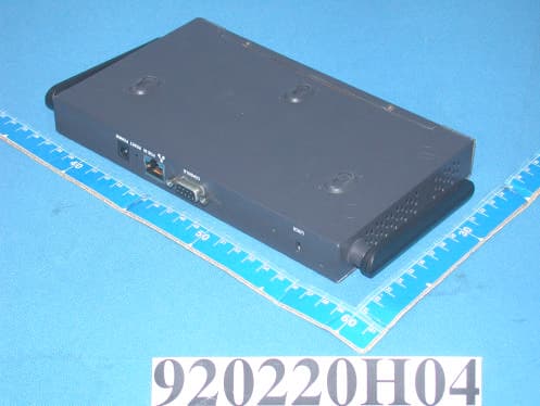
Click to zoom
Application Details
- Equipment Class
- NII - Unlicensed National Information Infrastructure TX
- Date of Grant
- Apr 22, 2003
- Application Purpose
- Original Equipment
- Date of Application
- Apr 22, 2003
- Equipment Note
- WLAN Dual Band Access Point
- Frequency Range
- 5725.00000000 - 5825.00000000
- Company
- Accton Technology Corp
- Country
- Taiwan
Documents & Files
Document Text
Text extracted from the exhibit documents filed with the FCC. Open a document above to read the original.
Users Manual
[email protected] www.adt.com.tw ADVANCE DATA TECHNOLOGY CORPORATION FEDERAL COMMUNICATIONS COMMISSION DECLARATION OF CONFORMITY (DoC) FOR THE FOLLOWING EQUIPMENT: PRODUCT NAME : WLAN Dual Band Access Point MODEL NO : WAP-50 ; WA6101B TRADE NAME : ARUBA Wireless Ne IS HEREWITH CONFIRMED AND FOUND TO COMPLY WITH THE REQUIREMENTS OF CFR 47 PART 15 REGULATION. THE RESULTS OF ELECTROMAGNETIC EMISSION EVALUATION ARE SHOWN IN THE REPORT NO : RF920225H04 THIS DEVICE COMPLIES WITH PART 15 OF THE FCC RULES. OPERATION IS SUBJECT TO THE FOLLOWING TWO CONDITIONS: (1) THIS DEVICE MAY NOT CAUSE HARMFUL INTERFERENCE AND, (2) THIS DEVICE MUST ACCEPT ANY INTERFERENCE RECEIVED, INCLUDING INTERFERENCE THAT MAY CAUSE UNDESIRED OPERATION. THE FOLLOWING LOCAL MANUFACTURER/IMPORTER IS RESPONSIBLE FOR THIS DECLARATION ManufacturerUSA Local Representative Company name: Accton Technology Corporation Company name: Aruba Wireless Networks Inc. Address: No.1, Creation Rd. III, Science-based Industrial Park, Hsinchu, Taiwan, R.O.C. Address: 180 Great Oaks Blvd. San Jose, CA, 95124, USA Contact Person: Hsoang-Shen Chen Contact Person: Loren Vorreiter Title: Section Manager Title: Mechanical Engineer Tel/Fax: Tel:886-3-5770270 Fax:886-3-5783839 Tel/Fax: Tel: 408-754-3048 Fax: 408-227-4550
Users Manual
4/1/03 Accton Draft—CONFIDENTIAL Aruba 50 Wireless Access Point Installation Guide TM 180 Great Oaks Blvd. Ste B San Jose, California 95119 Net www.arubanetworks.com Tel 408.227.4500 Fax 408.227.4550 4/1/03 Accton Draft—CONFIDENTIAL ii Aruba 50Part 0500007A Installation GuideMay 2003 Copyright Copyright © 2003 Aruba Wireless Networks, Inc. All rights reserved. Specifications in this manual are subject to change without notice. Originated in the USA. Trademarks AirOS, Aruba 50, and Aruba 5000 are trademarks of Aruba Wireless Networks in the United States and certain other countries. The K & Lock design is a registered trademark of the Kensington Technology Group in the United States and certain other countries. Any other trademarks appearing in this manual are owned by their respective companies. Aruba 50 iii Installation Guide 4/1/03 Accton Draft—CONFIDENTIAL Compliance FCC - Class B This equipment has been tested and found to comply with the limits for a Class B digital device, pursuant to Part 15 of the FCC Rules. These limits are designed to provide reasonable protection against harmful interference in a residential installation. This equipment generates, uses and can radiate radio frequency energy and, if not installed and used in accordance with instructions, may cause harmful interference to radio communications. However, there is no guarantee that the interference will not occur in a particular installation. If this equipment does cause harmful interference to radio or television reception, which can be determined by turning the equipment off and on, the user is encouraged to try to correct the interfer- ence by one or more of the following measures: zReorient the receiving antenna zIncrease the separation between the equipment and receiver zConnect the equipment into an outlet on a circuit different from that to which the receiver is con- nected zConsult the dealer or an experienced radio/TV technician for help FCC Caution: To assure continued compliance, use only shielded interface cables when connecting to computer or peripheral devices. Any changes or modifications not expressly approved by the party respon- sible for compliance could void the user’s authority to operate this equipment. This device complies with Part 15 of the FCC Rules. Operation is subject to the following two conditions: (1) This device may not cause harmful interference, and (2) this device must accept any interference received, including interference that may cause undesired operation. CAUTION STATEMENT: FCC RF Radiation Exposure Statement This equipment complies with FCC RF radiation exposure limits set forth for an uncontrolled environ- ment. This equipment should be installed and operated with a minimum distance of 20 centimeters (8 inches) between the radiator and your body. This transmitter must not be co-located or operating in con- junction with any other antenna or transmitter. Industry Canada - Class B This digital apparatus does not exceed the Class B limits for radio noise emissions from digital apparatus as set out in the interference-causing equipment standard entitled “Digital Apparatus,” ICES-003 of the Department of Communications. Cet appareil numérique respecte les limites de bruits radioélectriques applicables aux appareils numériques de Classe B prescrites dans la norme sur le matériel brouilleur: “Appareils Numériques,” NMB-003 édictée par le ministère des Communications. 4/1/03 Accton Draft—CONFIDENTIAL iv Aruba 50Part 0500007A Installation GuideMay 2003 Contents v 4/1/03 Accton Draft—CONFIDENTIAL Contents Preface. . . . . . . . . . . . . . . . . . . . . . vii Related Documents . . . . . . . . . . . . . . . . . . vii Text Conventions . . . . . . . . . . . . . . . . . . viii Contacting Aruba Wireless Networks . . . . . . . . . . ix Chapter 1 Introduction . . . . . . . . . . . . . . . . . . . 1 Product Features . . . . . . . . . . . . . . . . . . . . 1 Ethernet Compatibility . . . . . . . . . . . . . . . 2 Radio Characteristics . . . . . . . . . . . . . . . . 2 Power Over Ethernet . . . . . . . . . . . . . . . . 2 Physical Description . . . . . . . . . . . . . . . . . . 3 Package Checklist . . . . . . . . . . . . . . . . . 3 Top Panel . . . . . . . . . . . . . . . . . . . . . 3 Rear Panel . . . . . . . . . . . . . . . . . . . . . 5 Chapter 2 Setup & Installation . . . . . . . . . . . . . 7 Requirements . . . . . . . . . . . . . . . . . . . . . 7 Select a Network Topology . . . . . . . . . . . . . . . 8 Perform Initial Setup . . . . . . . . . . . . . . . . . . 10 Direct SPOE to the Aruba WLAN Switch . . . . . 10 Direct Terminal Connection . . . . . . . . . . . . 11 Configure the Aruba 50 . . . . . . . . . . . . . . . 12 Mount the Aruba 50 . . . . . . . . . . . . . . . . . . 14 Free-Standing Placement . . . . . . . . . . . . . . 15 Using the Mounting Kit . . . . . . . . . . . . . . 15 4/1/03 Accton Draft—CONFIDENTIAL vi Aruba 50Part 0500007A Installation GuideMay 2003 Connect Required Cables. . . . . . . . . . . . . . . . 18 Direct SPOE to the Aruba WLAN Switch . . . . . 18 LAN or POE Connection . . . . . . . . . . . . . . 19 Appendix A Troubleshooting . . . . . . . . . . . . . . . 21 Appendix B Port Specifications. . . . . . . . . . . . . 23 Console Port . . . . . . . . . . . . . . . . . . . . . . 23 FE Port . . . . . . . . . . . . . . . . . . . . . . . . 24 SPOE Adapter . . . . . . . . . . . . . . . . . . . . . 25 Appendix C Product Specifications. . . . . . . . . . 27 Preface vii 4/1/03 Accton Draft—CONFIDENTIAL Preface The preface includes the following information: zA list of related documentation for further reading zA key to the various text conventions used throughout this manual zAruba Wireless Networks support and service information Related Documents The following items are part of the complete documentation for the Aruba system: zAruba 50 Installation Guide (Part No. 050007A, May 2003) zAruba 5000 Installation Guide (Part No. 0500001A, May 2003) zAruba AirOS v1.0 User’s Guide…
Text truncated - open the document above for the full version.
Cover Letter(s)
American Telecommunications Certification Body Inc. 6731 Whittier Ave, McLean, VA 22101 April 8, 2003 RE: Accton Technology Corporation FCC ID: HEDWA6101BACC I have a few comments on the above referenced Application. 1) The RF exposure shows separate calculations for each mode of operation (802.11b, 802.11a, 802.11a turbo, etc.). Please explain if this device (under normal use by the user) may transmit simultaneously using both 802.11b and 802.11a. If so, please update the RF exposure to show the composite RF exposure condition which can occur. 2) Conducted emissions appear to only have been performed with the AC adapter. Please provide data or additional information showing compliance when powered by POE. 3) The antenna appears to contain 2 RF cables, one for 2.4 GHz and one for 5 GHz. Is the internal construction of the antenna actually contain 2 separate antennas, or is there a shared antenna internally. Note that a shared antenna would suggest a concern with mixing of both the 2.4 and 5 GHz signals, therefore created inter-modulation concerns if they operate at the same time and share the same RF antenna. 4) Only one set of powerline conducted emissions was provided for the UNII band. Please explain if various channels were investigated, normal and turbo modes investigated, and POE for the UNII band in effort to obtain the worse case results. Additionally, if the end user is expected to be able to use both the 802.11b and 802.11a simultaneously, then this mode should also be checked. 5) Page 63 & 64 of the test report shows limits that do not appear to match FCC limits. They appear to be 10 meter Class B limits. Please check the test distance and the limits and correct the report. 6) Two frequencies on page 69 (5715/5725) in the lower table are mislabeled as falling in a restricted band. Please correct. 7) Page 30 of 36 of the users manual shows the incorrect frequencies of operation for 802.11b use. Please correct. 8) The power output of page 30 of 36 states the minimum output power is +16 dBm. This is misleading since the maximum output power for 802.11b is +15 dBm. Please correct. Timothy R. Johnson Examining Engineer mailto: [email protected] The items indicated above must be submitted before processing can continue on the above referenced application. Failure to provide the requested information may result in application termination. Correspondence should be considered part of the permanent submission and may be viewed from the Internet after a Grant of Equipment Authorization is issued. Please do not respond to this correspondence using the email reply button. In order for your response to be processed expeditiously, you must submit your documents through the AmericanTCB.com website. Also, please note that partial responses increase processing time and should not be submitted. Any questions about the content of this correspondence should be directed to the sender.
Cover Letter(s)
Hi, Timothy R. Johnson For your question in attached comment: (1) This device will not transmit simultaneously both 802.11a and 802.11b . (2) This device is designed to function using POE and an AC adapter(See user manual). But actually , the product's package to U.S market will NOT include POE, so POE is considered as suport unit of test configuration ,and we only test radiated emissions of POE mode . We have upload revised report . (3) This is shared antenna for 802.11a and 802.11b . (4) Done! We had verifyed conducted emissions between normal mode and turbo mode , there is no deviation . About the POE , same as (2) . And end user can not use this product in 802.11a and 802.11b at the same time (see above (1) ). (5) Done! Uploaded revised test report. (6) Done! Uploaded revised test report. (7) Done! The revised Manual has been sunmitted to you. (8) Done! The revised Manual has been sunmitted to you. If you have any question, please contact with us. Your earliest response of this matter would be greatly appreciated! Best Regards, Amanda Chu / ¦¶ªÚ½Ë(Embedded image moved to file: pic27756.gif) ~~~~~~~~~~~~~~~~~~~~~~~~~~~~~~~~ Certification Specialist ADT Corp. (Hsin Chu Office) TEL: 03-5935343 FAX: 03-5935342 ~~~~~~~~~~~~~~~~~~~~~~~~~~~~~~~~ ----- Âà§eªÌ Eric Lin/ADT ©ó 2003/04/16 08:22 PM ----- To: [email protected] Cc: [email protected], [email protected], [email protected], [email protected] Subject: =?big5?B? pl6rSKFHIFJldmlldyBvZiBBY2N0b24gVGVjaG5vbG9neSBDb3Jwb3JhdGlvbiwg?= =?us-ascii?Q?FCC?= ID: HEDWA6101BACC Page 1 of 2In 4/21/2003Printed for "Timothy R. Johnson" <[email protected]> "Timothy R. Johnson" ¦¬¥ó¤H¡G [email protected] <tjohnson@Americ °Æ¥»§Û°e¡G anTCB.com> ¥D¦®¡G Review of Accton Technology Corporation, FCC ID: HEDWA6101BACC after recent uploads 2003/04/16 12:31 PM Eric, The newly provided test report addressed items 5 & 6. However it appears that the remaining items have still not been addressed. Please provide an update regarding your response. Additionally, it appears that the newly provided test report (part 1) has had much of the POE information removed. Please explain as this unit is designed to function using POE or an AC adapter. Thank You, Timothy R. Johnson NARTE Certified EMC Engineer No. EMC-002205-NE email: [email protected] alternate email: [email protected] (See attached file: ATCB Comment_ 040803.pdf) pic27756.gif =big5BQVRDQiBDb21tZW50XyAwNDA4MDMucGRm=.pdf Page 2 of 2In 4/21/2003Printed for "Timothy R. Johnson" <[email protected]>
External Photos
Page 1 CONSTRUCTION PHOTOS OF EUT
ID Label/Location Info
(Fig. 1) FCC ID: HEDWA6101BACC FCC LABEL LOCATION The label will be permanently affixed at a conspicuous location on the device. Label
ID Label/Location Info
ARUBA WIRELESS NETWORKS INC. E234335 I.T .E. 66F9 TITLE: LABEL,AGENCY,ACCESS POINT DWG NO: 4000012REV AC . ARUBA WIRELESS NETWORKS INC. This device complies with Part 15 of the FCC Rules. Operation is subject to the following two conditions: (1) This device may not cause harmful interference, and (2) This device must accept any interference received, including interference that may cause undesired operation. MODEL #: WAP-50 0560 FCC ID:HEDWA6101BACC IC:3857A-WA6101BA Complies with RSS-210ICES-003 CLASS B INPUT VOLTAGE RANGE 3.3V dc ,3A Made in xxxxxxx XXX 146xxxxxxxxxE r01xx MFG Countr y (Ariel Nar row, P oint 4) MFG Factory (Ariel Nar row, P oint 4) Vendor ID (Ariel Nar row, P oint 4) 60.0 mm 42.0 mm Mater ial: metalized + Glossy PP thickness: .2 mm Adhesive: UL Approved - Acr ylic Text color: B lack MFG Countr y Code SVA Accton (Shen Zhen) ---GZ Accton (Shen Zhen)---------AC MFG Countr y Decided by import and export countr y Vendor ID Decided by Vendor ID Number R 2.5 4 places !
Internal Photos
Page 1 CONSTRUCTION PHOTOS OF EUT Page 2 Page 3 Page 4 Page 5 Page 6 Page 7 Page 8 Page 9 Page 10 Page 11 Page 12
Operational Description
FCC ID: HEDWA6101BACC ADT No.920220H04 Technical Description The transmitter of the EUT is powered by host equipment. The antenna is Dipole Antenna with UFL connector and MMCX connector. This device is a WLAN Dual Band Access Point operates in both the 5GHz and 2.4GHz bands, the maximum data rate could be 108Mbps in turbo mode. For more detailed instruction, please take a look at the user’s manual. FCC 15.407(c) states : The device shall automatically discontinue transmission in case of either absence of information to transmit or operational failure. These provisions are not intended to preclude the transmission of control or signaling information or the use of repetitive codes used by certain digital technologies to complete frame or burst intervals. Applicants shall include in their application for equipment authorization a description of hoe this requirement is met. Data transmission is always initiated by software, which is then pass down through the MAC, through the digital and analog baseband, and finally to the RF chip. Several special packets (ACKs, CTS, PSPoll, etc...) are initiated by the MAC. There are the only ways the digital baseband portion will turn on the RF transmitter, which it then turns off at the end of the packet. Therefore, the transmitter will be on only while one of the aforementioned packets are being transmitted.
RF Exposure Info
FCC ID: HEDWA6101BACC ADT No.: 920220H04 FCC TEST REPORT REPORT NO.: RF920220H04 MODEL NO.: WAP-50, WA6101B ACCORDING: FCC Guidelines for Human Exposure IEEE C95.1 APPLICANT: Accton Technology Corporation ADDRESS: No.1, Creation Rd. III, Science-based Industrial Park, Hsinchu, Taiwan, R.O.C ISSUED BY: Advance Data Technology Corporation LAB LOCATION: 47 14th Lin, Chiapau Tsun, Linko, Taipei, Taiwan, R.O.C. 0536 ILAC MRA Lab Code: 200376-0 FCC ID: HEDWA6101BACC ADT No.: 920220H04 RF Exposure Measurement (Mobile Device) 1. Introduction In this document, we try to prove the safety of radiation harmfulness to the human body for our product. The limit for Maximum Permissible Exposure (MPE) specified in FCC 1.1310 is followed. The Gain of the antenna used in this product is measured in a Fully Anechoic Chamber (FAC) calibrated for antenna measurement in ADT, and also the maximum total power input to the antenna is measured. Through the Friis transmission formula and the maximum gain of the antenna, we can calculate the distance, away from the product, where the limit of MPE is reached. Although the Friis transmission formula is a far field assumption, the calculated result of that is an over-prediction for near field power density. We will take that as the worst case to specify the safety range. 2. Classification The antenna of the product, under normal use condition, is at least 20 cm away from the body of the user. Warning statement for keeping 20cm separation distance and the prohibition of operating next to a person has been printed on the users manual. So, this product is classified as the Mobile Device. 3. RF Exposure Limit According to FCC 1.1310: The criteria listed in the following table shall be used to evaluate the environmental impact of human exposure to radio-frequency (RF) radiation as specified in 1.1307(b) FCC ID: HEDWA6101BACC ADT No.: 920220H04 LIMITS FOR MAXIMUM PERMISSIBLE EXPOSURE (MPE) Frequency Range (MHz) Electric Field Strength (V/m) Magnetic Field Strength (A/m) Power Density (mW/cm 2 ) Average Time (minutes) (A)Limits For Occupational / Control Exposures 300-1500......F/3006 1500-100,000......56 (B)Limits For General Population / Uncontrolled Exposure 300-1500......F/15006 1500-100,000......1.030 F = Frequency in MHz 4. Friis Formula Friis transmission formula : Pd = (Pout*G) / (4*pi*r 2 ) where Pd = power density in mW/cm 2 Pout = output power to antenna in mW G = gain of antenna in linear scale Pi = 3.1416 R = distance between observation point and center of the radiator in cm Pd is the limit of MPE, 1 mW/cm 2 . If we know the maximum Gain of the antenna and the total power input to the antenna, through the calculation, we will know the distance r where the MPE limit is reached. Ref. : David K. Cheng, Field and Wave Electromagnetics, Second Edition, Page 640, Eq. (11-133). 5. EUT Operating condition The software provided by Manufacturer enabled the EUT to transmit and receive data at lowest, middle and highest channel individually. 6. Climate Condition The temperature and related humidity: 20 deg. C and 63 % RH FCC ID: HEDWA6101BACC ADT No.: 920220H04 7. Test Results 7.1 Antenna Gain The maximum Gain measured in Fully Anechoic Chamber are 4.5dBi or 2.82(numeric) for 5GHz and 1.5dBi or 1.41(numeric) for 2.4GHz. 7.2 Output Power Into Antenna & RF Exposure Distance : For Part 802.11b: CHANNEL CHANNEL FREQUENCY (MHz) OUTPUT POWER TO ANTENNA (mW) MINIMUM ALLOWABLE DISTANCE ( r ) FROM SKIN (Centi-Meter) 1241230.971.76 6243729.511.79 11246226.611.69 For Part 802.11a: Normal Mode: CHANNEL CHANNEL FREQUENCY (MHz) OUTPUT POWER TO ANTENNA (mW) MINIMUM ALLOWABLE DISTANCE ( r ) FROM SKIN (Centi-Meter) 1518048.643.28 4524047.863.32 55260100.924.61 8532078.342.74 9574574.984.25 12580578.704.19 Turbo Mode: CHANNEL CHANNEL FREQUENCY (MHz) OUTPUT POWER TO ANTENNA (mW) MINIMUM ALLOWABLE DISTANCE ( r ) FROM SKIN (Centi-Meter) 1521048.872.8 2525049.553.16 3529073.452.77 4576068.714.34 5580062.663.68 The minimum allowable distance is very close to the enclosure of the antenna and is very far away from the human being under normal use condition.
Test Report
FCC ID: HEDWA6101BACC Report No.: RF920220H041Issued: Mar. 19, 2003 ADT No.: 920220H04 FCC TEST REPORT REPORT NO.: RF920220H04 MODEL NO.: WAP-50, WA6101B RECEIVED: Feb. 20, 2003 TESTED: Feb. 25 to Mar. 15, 2003 APPLICANT: Accton Technology Corporation ADDRESS: No.1, Creation Rd. III, Science-based Industrial Park, Hsinchu, Taiwan, R.O.C ISSUED BY: Advance Data Technology Corporation LAB LOCATION: No. 81-1, Lu Liao Keng, 9 Ling, Wu Lung Tsuen, Chiung Lin Hsiang, Hsin Chu Hsien, Taiwan, R.O.C. This test report consists of 151 pages in total. It may be duplicated completely for legal use with the approval of the applicant. It should not be reproduced except in full, without the written approval of our laboratory. The client should not use it to claim product endorsement by CNLA, NVLAP or any government agencies. The test results in the report only apply to the tested sample. 0536 ILAC MRA Lab Code: 200376-0 FCC ID: HEDWA6101BACC Report No.: RF920220H042Issued: Mar. 19, 2003 ADT No.: 920220H04 Table of Contents 1.CERTIFICATION......................................................................................................5 2.SUMMARY OF TEST RESULTS...........................................................................6 3.GENERAL INFORMATION....................................................................................8 3.1GENERAL DESCRIPTION OF EUT................................................................................8 3.2DESCRIPTION OF TEST MODES................................................................................10 3.3GENERAL DESCRIPTION OF APPLIED STANDARDS..................................................11 3.4DESCRIPTION OF SUPPORT UNITS...........................................................................12 4.TEST TYPES AND RESULTS (FOR PART 802.11B)......................................15 4.1CONDUCTED EMISSION MEASUREMENT..................................................................15 4.1.1LIMITS OF CONDUCTED EMISSION MEASUREMENT.................................................15 4.1.2TEST INSTRUMENTS..................................................................................................15 4.1.3TEST PROCEDURES..................................................................................................16 4.1.4DEVIATION FROM TEST STANDARD..........................................................................16 4.1.5TEST SETUP...............................................................................................................17 4.1.6EUT OPERATING CONDITIONS..................................................................................17 4.1.7TEST RESULTS...........................................................................................................18 4.1.8TEST RESULTS...........................................................................................................24 4.2RADIATED EMISSION MEASUREMENT......................................................................26 4.2.1LIMITS OF RADIATED EMISSION MEASUREMENT.....................................................26 4.2.2TEST INSTRUMENTS..................................................................................................27 4.2.3TEST PROCEDURES..................................................................................................28 4.2.4DEVIATION FROM TEST STANDARD..........................................................................28 4.2.5TEST SETUP...............................................................................................................29 4.2.6EUT OPERATING CONDITIONS..................................................................................29 4.2.7TEST RESULTS...........................................................................................................30 4.36dB BANDWIDTH MEASUREMENT.............................................................................35 4.3.1LIMITS OF 6dB BANDWIDTH MEASUREMENT............................................................35 4.3.2TEST INSTRUMENTS..................................................................................................35 4.3.3TEST PROCEDURE....................................................................................................36 4.3.4DEVIATION FROM TEST STANDARD..........................................................................36 4.3.5TEST SETUP...............................................................................................................36 4.3.6EUT OPERATING CONDITIONS..................................................................................36 4.3.7TEST RESULTS...........................................................................................................37 4.4MAXIMUM PEAK OUTPUT POWER.............................................................................41 4.4.1LIMITS OF MAXIMUM PEAK OUTPUT POWER MEASUREMENT.................................41 4.4.2INSTRUMENTS...........................................................................................................41 4.4.3TEST PROCEDURES..................................................................................................42 4.4.4DEVIATION FROM TEST STANDARD..........................................................................42 4.4.5TEST SETUP...............................................................................................................42 FCC ID: HEDWA6101BACC Report No.: RF920220H043Issued: Mar. 19, 2003 ADT No.: 920220H04 4.4.6EUT OPERATING CONDITIONS..................................................................................42 4.4.7TEST RESULTS...........................................................................................................43 4.5POWER SPECTRAL DENSITY MEASUREMENT..........................................................44 4.5.1LIMITS OF POWER SPECTRAL DENSITY MEASUREMENT.........................................44 4.5.2TEST INSTRUMENTS....…
Text truncated - open the document above for the full version.
Test Report
FCC ID: HEDWA6101BACC Report No.: RF920220H0451Issued: Mar. 19, 2003 ADT No.: 920220H04 4.6.5 EUT OPERATING CONDITION Same as Item 4.3.6 4.6.6 TEST RESULTS The spectrum plots are attached on the following 2 pages. D2 line indicates the highest level, and D1 line indicates the 20dB offset below D2. It shows compliance with the requirement in part 15.247(C). NOTE: The band edge emission plot on the following two pages shows 53.22 / 53.95 dB delta between carrier maximum power and local maximum emission in restrict band (2.3830 GHz / 2.4864 GHz). The emission of carrier strength list in the test result of channel 1 at the item 4.2.7 (Page 28) is 92.3dBuV/m, so the maximum field strength in restrict band is 92.3-53.22=39.08dBuV/m which is under 54dBuV/m limit. FCC ID: HEDWA6101BACC Report No.: RF920220H0452Issued: Mar. 19, 2003 ADT No.: 920220H04 FCC ID: HEDWA6101BACC Report No.: RF920220H0453Issued: Mar. 19, 2003 ADT No.: 920220H04 FCC ID: HEDWA6101BACC Report No.: RF920220H0454Issued: Mar. 19, 2003 ADT No.: 920220H04 4.7 ANTENNA REQUIREMENT 4.7.1 STANDARD APPLICABLE For intentional device, according to FCC 47 CFR Section 15.203, an intentional radiator shall be designed to ensure that no antenna other than that furnished by the responsible party shall be used with the device. And according to FCC 47 CFR Section 15.247 (b), if transmitting antennas of directional gain greater than 6dBi are used, the power shall be reduced by the amount in dB that the directional gain of the antenna exceeds 6dBi. 4.7.2 ANTENNA CONNECTED CONSTRUCTION The antenna used in this product is Dipole Antenna with UFL Connector. The maximum Gain of the antenna is 1.5 dBi. FCC ID: HEDWA6101BACC Report No.: RF920220H0455Issued: Mar. 19, 2003 ADT No.: 920220H04 5. TEST TYPES AND RESULTS (FOR PART 802.11a) 5.1 CONDUCTED EMISSION MEASUREMENT 5.1.1 LIMITS OF CONDUCTED EMISSION MEASUREMENT FREQUENCY OF EMISSION (MHz)CONDUCTED LIMIT (dBμV) Quasi-peakAverage 0.15-0.5 0.5-5 5-30 66 to 56 56 60 56 to 46 46 50 NOTE:1.The lower limit shall apply at the transition frequencies. 2.The limit decreases in line with the logarithm of the frequency in the range of 0.15 to 0.50 MHz. 3.All emanations from a class A/B digital device or system, including any network of conductors and apparatus connected thereto, shall not exceed the level of field strengths specified above. 5.1.2 TEST INSTRUMENTS DESCRIPTION & MANUFACTURER MODEL NO.SERIAL NO. CALIBRATED UNTIL ROHDE & SCHWARZ Test Receiver ESCS 30847124/029Nov. 17, 2003 ROHDE & SCHWARZ LISN (for EUT) ESHS-Z5848773/004Nov. 13, 2003 KYORITSU LISN (for peripheral)KNW-4078/1395/12Jul. 23, 2003 RF Cable (JETBAO)RG233/UCable_CA_01Jul. 03, 2003 Terminator(for KYORITSU)503Apr. 11, 2003 SoftwareCond-V2eNANA NOTE:1. The calibration interval of the above test instruments is 12 months and the calibrations are traceable to NML/ROC and NIST/USA. 3. The test was performed in ADT Shielded Room No. A. 3. The VCCI Con A Registration No. is C-817. FCC ID: HEDWA6101BACC Report No.: RF920220H0456Issued: Mar. 19, 2003 ADT No.: 920220H04 5.1.3 TEST PROCEDURES a. The EUT was placed 0.4 meters from the conducting wall of the shielded room with EUT being connected to the power mains through a line impedance stabilization network (LISN). Other support units were connected to the power mains through another LISN. The two LISNs provide 50 ohm/ 50uH of coupling impedance for the measuring instrument. b. Both lines of the power mains connected to the EUT were checked for maximum conducted interference. c. The frequency range from 150 kHz to 30 MHz was searched. Emission levels over 10dB under the prescribed limits could not be reported 5.1.4 DEVIATION FROM TEST STANDARD No deviation FCC ID: HEDWA6101BACC Report No.: RF920220H0457Issued: Mar. 19, 2003 ADT No.: 920220H04 5.1.5 TEST SETUP For the actual test configuration, please refer to the related item – Photographs of the Test Configuration. 5.1.6 EUT OPERATING CONDITIONS Same as 4.1.6. FCC ID: HEDWA6101BACC Report No.: RF920220H0458Issued: Mar. 19, 2003 ADT No.: 920220H04 5.1.7 TEST RESULTS MODEL WAP-50 EUT WLAN Dual Band Access Point 6dB BANDWIDTH 9 kHz INPUT POWER (SYSTEM) 120Vac, 60 Hz PHASE Line (L) ENVIRONMENTAL CONDITIONS 25deg. C, 60RH, 976 hPa TESTED BY Tony Chen TEST MODE With Adapter Corr.Reading ValueEmission LevelLimitMargin Freq. Factor[dB (uV)][dB (uV)][dB (uV)](dB)No [MHz](dB)Q.P.AV.Q.P.AV.Q.P.AV.Q.P.AV. 10.2710.1045.87-45.97-61.0851.08-15.11- 20.6500.1043.87-43.97…
Text truncated - open the document above for the full version.
Contact Information
Applicant
Abby Wei(Manager)
Technical Contact
Advance Data Technology CorporationEric Lin
[email protected]+886-3-593-5343
81-1 Luliaoken, 9th Lin, Wulung Tsuen · Hsinchu · Taiwan
Non-Technical Contact
Advance Data Technology CorporationEric Lin
[email protected]+886-3-593-5343
Test Firm
Bureau Veritas CPS (H.K.) Ltd. Taoyuan BranchRichard Chen
Technical Specifications
| # | Rule Parts | Frequency Range | Power Output |
|---|---|---|---|
| 3 | 15E | 5.72 GHz - 5.83 GHz | 79.00 mW |
Other Applications from Accton Technology Corp

HEDEAP115
Jan 27, 2026Wi-Fi 7 AP
Equipment Class
NII - Unlicensed National Information Infrastructure TX
HEDEAP112
Oct 13, 2024Wi-Fi 6 IoT Gateway
Equipment Class
DTS - Digital Transmission System
HEDEAP111
Mar 17, 2024Wi-Fi 6 Access Point
Equipment Class
DTS - Digital Transmission System
HEDOAP101E
Oct 24, 2023Outdoor Access Point
Equipment Class
DTS - Digital Transmission System
HEDEAP104
Dec 14, 2022Indoor Wall Plate WiFi 6 Access Point
Equipment Class
DTS - Digital Transmission System