HEDWA6101BJEnterprise 11b Access Point
Accton Technology Corp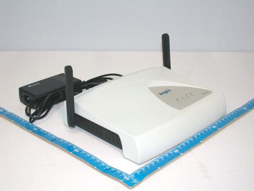
Click to zoom
Application Details
- Equipment Class
- DTS - Digital Transmission System
- Date of Grant
- Jul 22, 2003
- Application Purpose
- Original Equipment
- Date of Application
- Jul 22, 2003
- Equipment Note
- Enterprise 11b Access Point
- Frequency Range
- 2412.00000000 - 2462.00000000
- Company
- Accton Technology Corp
- Country
- Taiwan
Documents & Files
Document Text
Text extracted from the exhibit documents filed with the FCC. Open a document above to read the original.
Users Manual
Legra Systems Inc. Proprietary and Confidential Pr elim inary Legra Radio LR11b Installation Guide 009-10602-A June 2003 Legra Systems Inc. Proprietary and Confidential Pr elim inary ©2003 Legra Systems This equipment has been tested and found to comply with the limits for a Class B digital device, pursuant to Part 15 of the FCC Rules. These limits are designed to provide reasonable protection against harmful interference in a residential installation. This equipment generates, uses and can radiate radio frequency energy and, if not installed and used in accordance with instructions, may cause harmful interference to radio communications. However, there is no guarantee that the interference will not occur in a particular installation. If this equipment does cause harmful interference to radio or television reception, which can be determined by turning the equipment off and on, the user is encouraged to try to correct the interference by one or more of the following measures: •Reorient the receiving antenna •Increase the separation between the equipment and receiver •Connect the equipment into an outlet on a circuit different from that to which the receiver is connected •Consult the dealer or an experienced radio/TV technician for help FCC Caution: To assure continued compliance, (example - use only shielded interface cables when connecting to computer or peripheral devices). Any changes or modifications not expressly approved by the party responsible for compliance could void the user’s authority to operate this equipment. This device complies with Part 15 of the FCC Rules. Operation is subject to the following two conditions: (1) This device may not cause harmful interference, and (2) this device must accept any interference received, including interference that may cause undesired operation. This product includes cryptographic software written by Eric Young ([email protected]). THIS SOFTWARE IS PROVIDED BY ERIC YOUNG “AS IS” AND ANY EXPRESS OR IMPLIED WARRANTIES, INCLUDING, BUT NOT LIMITED TO, THE IMPLIED WARRANTIES OF MERCHANTABILITY AND FITNESS FOR A PARTICULAR PURPOSE ARE DISCLAIMED. IN NO EVENT SHALL THE AUTHOR OR CONTRIBUTORS BE LIABLE FOR ANY DIRECT, INDIRECT, INCIDENTAL, SPECIAL, EXEMPLARY, OR CONSEQUENTIAL DAMAGES (INCLUDING, BUT NOT LIMITED TO, PROCUREMENT OF SUBSTITUTE GOODS OR SERVICES; LOSS OF USE, DATA, OR PROFITS; OR BUSINESS INTERRUPTION) HOWEVER CAUSED AND ON ANY THEORY OF LIABILITY, WHETHER IN CONTRACT, STRICT LIABILITY, OR TORT (INCLUDING NEGLIGENCE OR OTHERWISE) ARISING IN ANY WAY OUT OF THE USE OF THIS SOFTWARE, EVEN IF ADVISED OF THE POSSIBILITY OF SUCH DAMAGE. All other trademarks mentioned in this document are the property of their respective owners. iii Legra Systems Inc. Proprietary and Confidential Contents Contents................................................................................... iii Figures ...................................................................................... v Tables...................................................................................... vii Introduction ............................................................................. ix Intended Audience ................................................................. ix Objective ................................................................................. ix About this Guide ..................................................................... x Documentation Conventions ................................................. x Related Documents ................................................................ xi Documentation Feedback .................................................... xii Technical Assistance ............................................................ xii Chapter 1Overview Key Features ............................................................................. 2 Power over Ethernet (PoE) Compatibility ................................................ 3 Radio Characteristics ............................................................................... 4 MAC Addresses ....................................................................................... 4 LED Indicators ......................................................................................... 4 Additional Tools/Items ............................................................... 7 Unpacking the Legra Radio ....................................................... 8 Package Contents ................................................................................... 8 Setup Overview ....................................................................... 10 LR11b Radio Configuration ................................................................... 11 iv Legra Systems Inc. Proprietary and Confidential Legra Manager LM6000 NMS User Guide009-30422-A Chapter 2Installation Safety Information ................................................................... 14 FCC Safety Compliance Statement ....................................................... 14 General Safety Guidelines ..................................................................... 14 Warnings ................................................................................................ 15 Installation Guidelines ............................................................. 16 Chapter 3Mounting Instructions Overview ................................................................................. 18 Installing the Mounting Bracket .............................................................. 18 Attaching the Legra Radio to the Mounting Bracket .............................. 19 Removing the Legra Radio from the Mounting Bracket ......................... 20 Imprinting a Legra Radio ....................................................................... 20 Connecting Power to the Legra Radio ................................................... 21 Power over Ethernet (PoE) ................................................…
Text truncated - open the document above for the full version.
Cover Letter(s)
[email protected] www.adt.com.tw ADVANCE DATA TECHNOLOGY CORPORATION FEDERAL COMMUNICATIONS COMMISSION DECLARATION OF CONFORMITY (DoC) FOR THE FOLLOWING EQUIPMENT: PRODUCT NAME : Enterprise 11b Access point MODEL NO : LR11b TRADE NAME : Legra IS HEREWITH CONFIRMED AND FOUND TO COMPLY WITH THE REQUIREMENTS OF CFR 47 PART 15 REGULATION. THE RESULTS OF ELECTROMAGNETIC EMISSION EVALUATION ARE SHOWN IN THE REPORT NO : RF920217H02B THIS DEVICE COMPLIES WITH PART 15 OF THE FCC RULES. OPERATION IS SUBJECT TO THE FOLLOWING TWO CONDITIONS: (1) THIS DEVICE MAY NOT CAUSE HARMFUL INTERFERENCE AND, (2) THIS DEVICE MUST ACCEPT ANY INTERFERENCE RECEIVED, INCLUDING INTERFERENCE THAT MAY CAUSE UNDESIRED OPERATION. THE FOLLOWING LOCAL MANUFACTURER/IMPORTER IS RESPONSIBLE FOR THIS DECLARATION Manufacturer USA Local Representative Company name: Accton Technology Corporation Company name: To Be Determined. Address: No.1, Creation Rd. III, Science-based Industrial Park, Hsinchu, Taiwan, R.O.C. Address: Contact Person: Hsoang-Shen Chen Contact Person: Title: Section Manager Title: Tel/Fax: Tel:886-3-5770270 Fax:886-3-5783839 Tel/Fax:
Cover Letter(s)
American Telecommunications Certification Body Inc. 6731 Whittier Ave, McLean, VA 22101 July 18, 2003 RE: FCC ID: HEDWA6101BJ_ATCB000601 Attention: Eric Lin I have a few comments on this Application. 1. Please note that the FCC ID label information must also contain the FCC ID number. Please provide a label sample that has the actual FCC ID on the label. - 2. Please note that the block diagram of the system shows 802.11a/b. The 731 is only for 802.11b. The manual states that the device is only 802.11b (15.247). Please also note that the schematics appear to indicate a fully functional 802.11a min-PCI slot. Please explain why the mini-PCI slot is shown in the photos, in the block diagram and in the schematics. Is the 802.11a disabled? How, etc? If the slot is not disabled, how do you prevent insertion of an 802.11a miniPCI card? - 3. Please note that the operational description states the device is both a 15.247 and a 15.407 device. There is no indication on the 731 form nor in the report of 15.407 operation. As mentioned in item 2 there appears to be in fact a slot available for another miniPCI card of 15.407 capability. Please provide 15.407 test data. Alternately please explain how the manufacturer disables the second slot and please explain how this device is only a 15.247 device as submitted. - 4. FYI – Please note that the actual limit in the restricted bands above 1GHz is an average reading. The 20dB over the average is an additional requirement. However, limits on pass fail must address both. In your report you show an erroneous margin. The peak is only compared to the 20dB over limit and is not compared to the actual average limit. This means that the peaks (i.e. no average measurements were taken) for those frequencies listed they are actually 20dB closer to the limit than stated in the report. For example 4176 MHz is not 23.1dB under the limit but actually only 3.1dB under the actual limit of 54dB. - 5. Dennis Ward mailto:[email protected] The items indicated above must be submitted before processing can continue on the above referenced application. Failure to provide the requested information may result in application termination. Correspondence should be considered part of the permanent submission and may be viewed from the Internet after a Grant of Equipment Authorization is issued. Please do not respond to this correspondence using the email reply button. In order for your response to be processed expeditiously, you must submit your documents through the AmericanTCB.com website. Also, please note that partial responses increase processing time and should not be submitted. Any questions about the content of this correspondence should be directed to the sender.
External Photos
Page 1 CONSTRUCTION PHOTOS OF EUT Page 2
Internal Photos
Page 1 CONSTRUCTION PHOTOS OF EUT Page 2 Page 3 Page 4 Page 5 Page 6 Page 7 Page 8 Page 9 Page 10 Page 11 Page 12 Page 13 Page 14
Operational Description
FCC ID: HEDWA6101BJ ADT No. 920627H01 Technical Description The transmitter of the EUT is powered by AC adapter or POE. The antenna is Integral Antenna with UFL connector. For more detailed instruction, please take a look at the user’s manual. DSSS Information This device is Direct Sequence Spread Spectrum, the data is mixed by pseudorandom code which is an orthogonal code. The mixed data is digital modulated by BPSK and QPSK technique depends on the data rates. The CCK coding is applied for increasing the data rate, and also the processing gain will be increased. The bit rates are 1,2,5.5,11Mbps, the symbol rates are 1,1,1.375,1.375Mbps, the chip rates are always 11Mbps. So, the Chip/symbol is 11,11,8 and 8 respectively. Although is higher bit rate, the processing gain is lower than 10, but the CCK coding used in higher bit rate will provide 2.2dB coding gain.
RF Exposure Info
FCC ID: HEDWA6101BJ ADT No.: 920217H02B 1 FCC TEST REPORT REPORT NO.: RF920217H02B MODEL NO.: LR11b ACCORDING: FCC Guidelines for Human Exposure IEEE C95.1 APPLICANT: Accton Technology Corporation ADDRESS: No.1, Creation Rd. III, Science-based Industrial Park, Hsinchu, Taiwan, R.O.C ISSUED BY: Advance Data Technology Corporation LAB LOCATION: 47 14th Lin, Chiapau Tsun, Linko, Taipei, Taiwan, R.O.C. Lab Code: 200376-0 FCC ID: HEDWA6101BJ ADT No.: 920217H02B 2 RF Exposure Measurement 1. Introduction In this document, we try to prove the safety of radiation harmfulness to the human body for our product. The limit for Maximum Permissible Exposure (MPE) specified in FCC 1.1310 is followed. The Gain of the antenna used in this product is measured in a Fully Anechoic Chamber (FAC) calibrated for antenna measurement in ADT, and also the maximum total power input to the antenna is measured. Through the Friis transmission formula and the maximum gain of the antenna, we can calculate the distance, away from the product, where the limit of MPE is reached. Although the Friis transmission formula is a far field assumption, the calculated result of that is an over-prediction for near field power density. We will take that as the worst case to specify the safety range. 2. RF Exposure Limit According to FCC 1.1310: The criteria listed in the following table shall be used to evaluate the environmental impact of human exposure to radio-frequency (RF) radiation as specified in 1.1307(b) LIMITS FOR MAXIMUM PERMISSIBLE EXPOSURE (MPE) Frequency Range (MHz) Electric Field Strength (V/m) Magnetic Field Strength (A/m) Power Density (mW/cm 2 ) Average Time (minutes) (A)Limits For Occupational / Control Exposures 300-1500......F/3006 1500-100,000......56 (B)Limits For General Population / Uncontrolled Exposure 300-1500......F/15006 1500-100,000......1.030 F = Frequency in MHz FCC ID: HEDWA6101BJ ADT No.: 920217H02B 3 3. Friis Formula Friis transmission formula : Pd = (Pout*G) / (4*pi*r 2 ) where Pd = power density in mW/cm 2 Pout = output power to antenna in mW G = gain of antenna in linear scale Pi = 3.1416 R = distance between observation point and center of the radiator in cm Pd is the limit of MPE, 1 mW/cm 2 . If we know the maximum Gain of the antenna and the total power input to the antenna, through the calculation, we will know the MPE value at distance 20cm. Ref. : David K. Cheng, Field and Wave Electromagnetics, Second Edition, Page 640, Eq. (11-133). 4. EUT Operating condition The software provided by Manufacturer enabled the EUT to transmit and receive data at lowest, middle and highest channel individually. 5. Classification This device is not fixed inside the host equipment, it is connected with host through wire. So it is easy to be re-located in the place where at least 20 cm far away from the body of the user. Warning statement to the user for keeping at least 20cm or more separation distance with the antenna should be included in users manual. So, this device is classified as Mobile Device. FCC ID: HEDWA6101BJ ADT No.: 920217H02B 4 6. Test Results 6.1 Antenna Gain The maximum Gain measured in Fully Anechoic Chamber are 4.5dBi or 2.82(numeric) for 5GHz and 1dBi or 1.25(numeric) for 2.4GHz. 6.2 Output Power Into Antenna & RF Exposure Distance : Channel Channel Frequency (MHz) Output Power to Antenna (mW) Power Density (mW/cm 2 ) Limit of Power Density (mW/cm 2 ) 1241231.190.00881.0 6243732.510.00911.0 11246228.910.00081.0
Test Report
FCC ID: HEDWA6101BJ Report No.: RF920217H02B1Issued: Mar. 17, 2003 ADT No.: 920627H01 FCC TEST REPORT REPORT NO.: RF920217H02B MODEL NO.: LR11b RECEIVED: Feb. 17, 2003 TESTED: Feb. 19 Mar. 12, 2003 APPLICANT: Accton Technology Corporation ADDRESS: No.1, Creation Rd. III, Science-based Industrial Park, Hsinchu, Taiwan, R.O.C ISSUED BY: Advance Data Technology Corporation LAB LOCATION: No. 81-1, Lu Liao Keng, 9 Ling, Wu Lung Tsuen, Chiung Lin Hsiang, Hsin Chu Hsien, Taiwan, R.O.C. This test report consists of 53 pages in total. It may be duplicated completely for legal use with the approval of the applicant. It should not be reproduced except in full, without the written approval of our laboratory. The client should not use it to claim product endorsement by CNLA, NVLAP or any government agencies. The test results in the report only apply to the tested sample. 0536 ILAC MRA Lab Code: 200376-0 FCC ID: HEDWA6101BJ Report No.: RF920217H02B2Issued: Mar. 17, 2003 ADT No.: 920627H01 Table of Contents 1.CERTIFICATION............................................................................................................4 2.SUMMARY OF TEST RESULTS.....................................................................................5 3.GENERAL INFORMATION.............................................................................................6 3.1GENERAL DESCRIPTION OF EUT................................................................................6 3.2DESCRIPTION OF TEST MODES..................................................................................7 3.3GENERAL DESCRIPTION OF APPLIED STANDARDS....................................................8 3.4DESCRIPTION OF SUPPORT UNITS.............................................................................9 3.5CONDUCTED EMISSION MEASUREMENT..................................................................12 3.5.1LIMITS OF CONDUCTED EMISSION MEASUREMENT.................................................12 3.5.2TEST INSTRUMENTS..................................................................................................12 3.5.3TEST PROCEDURES..................................................................................................13 3.5.4DEVIATION FROM TEST STANDARD..........................................................................13 3.5.5TEST SETUP...............................................................................................................14 3.5.6EUT OPERATING CONDITIONS..................................................................................14 3.5.7TEST RESULTS...........................................................................................................15 3.6RADIATED EMISSION MEASUREMENT......................................................................21 3.6.1LIMITS OF RADIATED EMISSION MEASUREMENT.....................................................21 3.6.2TEST INSTRUMENTS..................................................................................................22 3.6.3TEST PROCEDURES..................................................................................................23 3.6.4DEVIATION FROM TEST STANDARD..........................................................................23 3.6.5TEST SETUP...............................................................................................................24 3.6.6EUT OPERATING CONDITIONS..................................................................................24 3.6.7TEST RESULTS...........................................................................................................25 3.76DB BANDWIDTH MEASUREMENT.............................................................................30 3.7.1LIMITS OF 6DB BANDWIDTH MEASUREMENT...........................................................30 3.7.2TEST INSTRUMENTS..................................................................................................30 3.7.3TEST PROCEDURE....................................................................................................31 3.7.4DEVIATION FROM TEST STANDARD..........................................................................31 3.7.5TEST SETUP...............................................................................................................31 3.7.6EUT OPERATING CONDITIONS..................................................................................31 3.7.7TEST RESULTS...........................................................................................................32 3.8MAXIMUM PEAK OUTPUT POWER.............................................................................36 3.8.1LIMITS OF MAXIMUM PEAK OUTPUT POWER MEASUREMENT.................................36 3.8.2TEST INSTRUMENTS..................................................................................................36 3.8.3TEST PROCEDURES..................................................................................................37 3.8.4TEST SETUP...............................................................................................................37 3.8.5EUT OPERATING CONDITIONS..................................................................................37 3.8.6TEST RESULTS...........................................................................................................38 3.9POWER SPECTRAL DENSITY MEASUREMENT..........................................................39 3.9.1LIMITS OF POWER SPECTRAL DENSITY MEASUREMENT.........................................39 3.9.2TEST INSTRUMENTS..................................................................................................39 FCC ID: HEDWA6101BJ Report No.: RF920217H02B3Issued: Mar. 17, 2003 ADT No.: 920627H01 3.9.3TEST PROCEDURE....................................................................................................40 3.9.4DEVIATION FROM TEST STANDARD..............................................................…
Text truncated - open the document above for the full version.
Test Setup Photos
FCC ID: HEDWA6101BJ Report No.: RF920217H02B50Issued: Mar. 17, 2003 ADT No.: 920627H01 4. PHOTOGRAPHS OF THE TEST CONFIGURATION CONDUCTED EMISSION TEST FCC ID: HEDWA6101BJ Report No.: RF920217H02B51Issued: Mar. 17, 2003 ADT No.: 920627H01 RADIATED EMISSION TEST (With Adapter) FCC ID: HEDWA6101BJ Report No.: RF920217H02B52Issued: Mar. 17, 2003 ADT No.: 920627H01 RADIATED EMISSION TEST (With POE)
Contact Information
Applicant
Abby Wei(Manager)
Technical Contact
Advanced Data Technology CorporationEric Lin
[email protected]886 3 593 5343
81-1 Luliaoken, 9th Lin, Wulung Tsuen · Chiunglin · Taiwan
Test Firm
Bureau Veritas CPS (H.K.) Ltd. Taoyuan BranchRichard Chen
Technical Specifications
| # | Rule Parts | Frequency Range | Power Output |
|---|---|---|---|
| 1 | 15C | 2.41 GHz - 2.46 GHz | 32.50 mW |
Other Applications from Accton Technology Corp

HEDEAP115
Jan 27, 2026Wi-Fi 7 AP
Equipment Class
NII - Unlicensed National Information Infrastructure TX
HEDEAP112
Oct 13, 2024Wi-Fi 6 IoT Gateway
Equipment Class
DTS - Digital Transmission System
HEDEAP111
Mar 17, 2024Wi-Fi 6 Access Point
Equipment Class
DTS - Digital Transmission System
HEDOAP101E
Oct 24, 2023Outdoor Access Point
Equipment Class
DTS - Digital Transmission System
HEDEAP104
Dec 14, 2022Indoor Wall Plate WiFi 6 Access Point
Equipment Class
DTS - Digital Transmission System