HEDWG3005DACCBarricade Wireless Router
Accton Technology Corp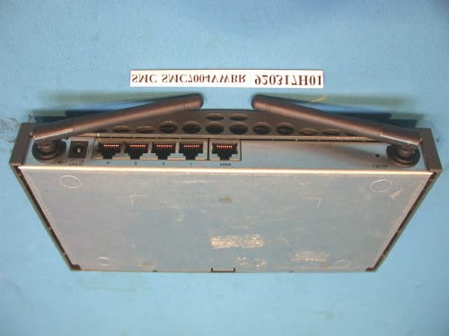
Click to zoom
Application Details
- Equipment Class
- DTS - Digital Transmission System
- Date of Grant
- May 15, 2003
- Application Purpose
- Original Equipment
- Date of Application
- May 15, 2003
- Equipment Note
- Barricade Wireless Router
- Frequency Range
- 2412.00000000 - 2462.00000000
- Company
- Accton Technology Corp
- Country
- Taiwan
Documents & Files
Document Text
Text extracted from the exhibit documents filed with the FCC. Open a document above to read the original.
Users Manual
38 Tesla Irvine, CA 92618 Phone: (949) 679-8000 Barricade TM 2.4 GHz 11 Mbps Wireless Cable/DSL Broadband Router User Guide From SMC’s Barricade line of Broadband Routers April 2003 Pub. # 150000026400E COPYRIGHT Information furnished by SMC Networks, Inc. (SMC) is believed to be accurate and reliable. However, no responsibility is assumed by SMC for its use, nor for any infringements of patents or other rights of third parties which may result from its use. No license is granted by implication or otherwise under any patent or patent rights of SMC. SMC reserves the right to change specifications at any time without notice. Copyright © 2003 by SMC Networks, Inc. 38 Tesla Irvine, CA 92618 All rights reserved. Printed in Taiwan Trademarks: SMC is a registered trademark; and Barricade is a trademark of SMC Networks, Inc. Other product and company names are trademarks or registered trademarks of their respective holders. i COMPLIANCES FCC - Class B This equipment has been tested and found to comply with the limits for a Class B digital device, pursuant to Part 15 of the FCC Rules. These limits are designed to provide reasonable protection against harmful interference in a residential installation. This equipment generates, uses and can radiate radio frequency energy and, if not installed and used in accordance with instructions, may cause harmful interference to radio communications. However, there is no guarantee that the interference will not occur in a particular installation. If this equipment does cause harmful interference to radio or television reception, which can be determined by turning the equipment off and on, the user is encouraged to try to correct the interference by one or more of the following measures: •Reorient the receiving antenna •Increase the separation between the equipment and receiver •Connect the equipment into an outlet on a circuit different from that to which the receiver is connected •Consult the dealer or an experienced radio/TV technician for help FCC Caution: To assure continued compliance, (example - use only shielded interface cables when connecting to computer or peripheral devices) any changes or modifications not expressly approved by the party responsible for compliance could void the user’s authority to operate this equipment. This device complies with Part 15 of the FCC Rules. Operation is subject to the following two conditions: (1) This device may not cause harmful interference, and (2) this device must accept any interference received, including interference that may cause undesired operation. IMPORTANT NOTE: FCC Radiation Exposure Statement This equipment complies with FCC radiation exposure limits set forth for an uncontrolled environment. This transmitter must not be co-located or operating in conjunction with any other antenna or transmitter. Compliances ii Industry Canada - Class B This digital apparatus does not exceed the Class B limits for radio noise emissions from digital apparatus as set out in the interference-causing equipment standard entitled “Digital Apparatus,” ICES-003 of the Department of Communications. Cet appareil numérique respecte les limites de bruits radioélectriques applicables aux appareils numériques de Classe B prescrites dans la norme sur le matériel brouilleur: “Appareils Numériques,” NMB-003 édictée par le ministère des Communications. EC Conformance Declaration - Class B SMC contact for these products in Europe is: SMC Networks Europe, Edificio Conata II, Calle Fructuós Gelabert 6-8, 2 o , 4 a , 08970 - Sant Joan Despí, Barcelona, Spain. This information technology equipment complies with the requirements of the Council Directive 89/336/EEC on the Approximation of the laws of the Member States relating to Electromagnetic Compatibility and 73/23/EEC for electrical equipment used within certain voltage limits and the Amendment Directive 93/68/ EEC. For the evaluation of the compliance with these Directives, the following standards were applied: RFI Emission: * Limit class B according to EN 55022:1998 * Limit class B for harmonic current emission according to EN 61000-3-2/1995 * Limitation of voltage fluctuation and flicker in low-voltage supply system according to EN 61000-3-3/1995 Immunity:* Product family standard according to EN 55024:1998 * Electrostatic Discharge according to EN 61000-4-2:1995 (Contact Discharge: ±4 kV, Air Discharge: ±8 kV) * Radio-frequency electromagnetic field according to EN 61000-4-3: 1996 (80 - 1000 MHz with 1 kHz AM 80% Modulation: 3 V/m) * Electrical fast transient/burst according to EN 61000-4-4:1995(AC/DC power supply: ±1 kV, Data/Signal lines: ±0.5 kV) * Surge immunity test according to EN 61000-4-5:1995(AC/DC Line to Line: ±1 kV, AC/DC Line to Earth: ±2 kV) * Immunity to conducted disturbances, Induced by radio-frequency fields: EN 61000-4-6:1996(0.15 - 80 MHz with 1 kHz AM 80% Modulation: 3 V/m) * Power frequency magnetic field immunity test according to EN 61000-4-8:1993(1 A/m at frequency 50 Hz) * Voltage dips, short interruptions and voltage variations immunity test according to EN 61000-4-11:1994(>95% Reduction @10 ms, 30% Reduction @500 ms, >95% Reduction @5000 ms) LVD:* EN60950(A1/1992; A2/1993; A3/1993; A4/1995; A11/1997) iii TABLE OF CONTENTS About the Wireless Barricade Router . . . . . . . . . 1 LED Indicators . . . . . . . . . . . . . . . . . . . . . . . . . . . . . . . . . . . . . . 1 Features and Benefits . . . . . . . . . . . . . . . . . . . . . . . . . . . . . . . . 2 Installing the Wireless Barricade Router . . . . . . . 3 Package Contents . . . . . . . . . . . . . . . . . . . . . . . . . . . . . . . . . . . 3 Hardware Description . . . . . . . . . . . . . . . . . . . . . . . . . . . . . . . . . 4 System Requirements . . . . . . . . . . . . . . . . . . . . . . . . . . . . . . . . 6 Connect the System . . . . . . . . . . . . . . . . . . . . . . . . . . . . . . . . . . 7 Basic Installation Procedure . . . . . . . . . . . . . . . . . . . . . . . 7 Configuring Client TC…
Text truncated - open the document above for the full version.
Users Manual
Configuring the Wireless Barricade Router 44 LAN •LAN IP – Use the LAN menu to configure the LAN IP address for the Wireless Barricade and to enable the DHCP server for dynamic client address allocation. •Set a period for the lease time if required. For home networks this may be set to Forever, which means there is no time limit on the IP address lease. •IP Address Pool – A dynamic IP start address may be specified by the user, e.g. 192.168.2.100 (default value). Once this start IP address has been assigned, IP addresses running from 192.168.2.100 to 192.168.2.199 will be part of the dynamic IP address pool. IP addresses from 192.168.2.2 to 192.168.2.99, and 192.168.2.200 to 192.168.2.254 will be available as static IP addresses. Remember not to include the address of the Wireless Barricade in the client address pool. Also remember to configure your client PCs for dynamic IP address allocation. Advanced Setup 45 Wireless To configure the Wireless Barricade as a wireless access point for wireless clients (either stationary or roaming), all you need to do is define the radio channel, the Service Set identifier (SSID), and encryption options. Channel and SSID You must specify a common radio channel and SSID (Service Set ID) to be used by the Wireless Barricade and all of your wireless clients. Be sure you configure all of your clients to the same values. ESSID: The Service Set ID. This should be set to the same value as other wireless devices in your network. (Default: SMC.) Note:The SSID is case sensitive and can consist of up to 32 alphanumeric characters. Configuring the Wireless Barricade Router 46 Transmission Rate: Set the data rate transmitted from the Wireless Barricade. The lower the data rate, the longer the transmission distance. (Default: Fully Automatic.) Basic Rate: The highest rate specified is the rate the Wireless Barricade will use when transmitting broadcast/multicast and management frames. Available options are: 1, 2, 5.5, and 11Mbps. (Default: 2Mbps.) Channel: The radio channel through which the Wireless Barricade communicates with PCs in its BSS. (Default: Auto) Note:The available channel settings are limited by local regulations. Encryption If you are transmitting sensitive data across wireless channels, you should enable Wired Equivalent Privacy (WEP) encryption. Encryption requires you to use the same set of encryption/decryption keys for the Wireless Barricade and all of your wireless clients. You can choose between standard 64-bit or the more robust 128-bit encryption. Advanced Setup 47 You may automatically generate encryption keys or manually enter the keys. For automatic 64-bit security, enter a passphrase and click Generate. Four keys will be generated (as shown below). Choose a key from the dropdown list or accept the default key. Automatic 128-bit security generates a single key. Configuring the Wireless Barricade Router 48 If you use encryption, configure the same keys used for the Wireless Barricade on each of your wireless clients. Note that Wired Equivalent Privacy (WEP) protects data transmitted between wireless nodes, but does not protect any transmissions over your wired network or over the Internet. Network Address Translation (NAT) From this section you can configure the Address Mapping, Virtual Server, and Special Application features that provide control over the port openings in the Wireless Barricade’s firewall. This section can be used to support several Internet based applications such as VPN Address Mapping Allows one or more public IP addresses to be shared by multiple internal users. Enter the Public IP address you wish to share into the Global IP field. Enter a range of internal IPs that will share the global IP. Advanced Setup 49 Virtual Server If you configure the Wireless Barricade as a virtual server, remote users accessing services such as Web or FTP at your local site via public IP addresses can be automatically redirected to local servers configured with private IP addresses. In other words, depending on the requested service (TCP/UDP port number), the Wireless Barricade redirects the external service request to the appropriate server (located at another internal IP address). For example, if you set Type/Public Port to TCP/80 (HTTP or Web) and the Private IP/Port to 192.168.2.2/80, then all HTTP requests from outside users will be transferred to 192.168.2.2 on port 80. Therefore, by just entering the IP Address provided by the ISP, Internet users can access the service they need at the local address to which you redirect them. The more common TCP service ports include: HTTP: 80, FTP: 21, Telnet: 23, and POP3: 110. Configuring the Wireless Barricade Router 50 Special Applications Some applications, such as Internet gaming, videoconferencing, Internet telephony and others, require multiple connections. These applications cannot work with Network Address Translation (NAT) enabled. If you need to run applications that require multiple connections, use the following screen to specify the additional public ports to be opened for each application. Specify the public port number normally associated with an application in the Trigger Port field. Set the protocol type to TCP or UDP, then enter the ports that the application requires. The ports may be in the format 7, 11, 57, or in a range, e.g., 72-96, or a combination of both, e.g., 7, 11, 57, 72-96. For a full list of ports and the services that run on them, see www.iana.org/assignments/port-numbers. Advanced Setup 51 Firewall the Wireless Barricade firewall can provide access control of connected client PCs, block common hacker attacks, including IP Spoofing, Land Attack, Ping of Death, IP with zero length, Smurf Attack, UDP port loopback, Snork Attack, TCP null scan, and TCP SYN flooding. The firewall does not significantly affect system performance, so we advise leaving it enabled to protect your network users. Access Control Using this option allows you to specify different privileges b…
Text truncated - open the document above for the full version.
Cover Letter(s)
[email protected] www.adt.com.tw ADVANCE DATA TECHNOLOGY CORPORATION FEDERAL COMMUNICATIONS COMMISSION DECLARATION OF CONFORMITY (DoC) FOR THE FOLLOWING EQUIPMENT: PRODUCT NAME : MODEL NO : SMC7004VWBR; WG3005D TRADE NAME : SMC IS HEREWITH CONFIRMED AND FOUND TO COMPLY WITH THE REQUIREMENTS OF CFR 47 PART 15 REGULATION. THE RESULTS OF ELECTROMAGNETIC EMISSION EVALUATION ARE SHOWN IN THE REPORT NO : RF920317H01 THIS DEVICE COMPLIES WITH PART 15 OF THE FCC RULES. OPERATION IS SUBJECT TO THE FOLLOWING TWO CONDITIONS: (1) THIS DEVICE MAY NOT CAUSE HARMFUL INTERFERENCE AND, (2) THIS DEVICE MUST ACCEPT ANY INTERFERENCE RECEIVED, INCLUDING INTERFERENCE THAT MAY CAUSE UNDESIRED OPERATION. THE FOLLOWING LOCAL MANUFACTURER/IMPORTER IS RESPONSIBLE FOR THIS DECLARATION ManufacturerUSA Local Representative Company name: Accton Technology Corporation Company name: SMC Networks Address: No.1, Creation Rd. III, Science-based Industrial Park, Hsinchu, Taiwan, R.O.C. Address: 38 Tesla Irvine, CA 92618 Contact Person: Hsoang-Shen Chen Contact Person: Kelaine Hamilton Title: Section Manager Title: Product Line Manager Tel/Fax: Tel:886-3-5770270 Fax:886-3-5783839 Tel/Fax: Tel:949-981-5912 Fax:949-679-1481
Cover Letter(s)
American Telecommunications Certification Body Inc. 6731 Whittier Ave, McLean, VA 22101 May 14, 2003 RE: FCC ID: HEDWG3005DACC Attention: Eric Lin I have a few comments on this Application. 1. Please note that block diagrams must be in accordance with 2.1033(b)(5) which states, “(5) A block diagram showing the frequency of all oscillators in the device. The signal path and frequency shall be indicated at each block.” The block diagram provided does not show the frequencies involved in the device. Please provide a block diagram in accordance with 2.1033(b)(5). 2. Your report on page 6 lists the operating frequency range of 2412 to 2472. The 731 and test data shows 2421 to 2462 (the proper US frequencies). Please correct page 6 of the report to reflect the proper frequency bands of use for this device. 3. FYI - Please note that the conducted emissions plots appear to be unusually low (i.e. while possible, the noise floor appears extremely low for an LISN as specified in the equipment list). Please verify that all attenuation and loss has been accounted for. 4. FYI - Please note that the PPSD plots on pages 40 through 42 do not look like a typical PPSD measurement plot that would be expected for this type device. Please explain. 5. FYI - Please note that the FCC ID number on the 731 does not match the 731 in the label sample nor in the reports. Please correct the 731 form FCC ID number. Dennis Ward mailto:[email protected] The items indicated above must be submitted before processing can continue on the above referenced application. Failure to provide the requested information may result in application termination. Correspondence should be considered part of the permanent submission and may be viewed from the Internet after a Grant of Equipment Authorization is issued. Please do not respond to this correspondence using the email reply button. In order for your response to be processed expeditiously, you must submit your documents through the AmericanTCB.com website. Also, please note that partial responses increase processing time and should not be submitted. Any questions about the content of this correspondence should be directed to the sender.
External Photos
Page 1 CONSTRUCTION PHOTOS OF EUT Page 2
ID Label/Location Info
(Fig. 1) FCC ID: FCC LABEL LOCATION The label will be permanently affixed at a conspicuous location on the device. Label
ID Label/Location Info
4 2 m m 60 mm
Internal Photos
Page 1 CONSTRUCTION PHOTOS OF EUT Page 2 Page 3 Page 4 Page 5 Page 6 Page 7 Page 8
Operational Description
FCC ID: HEDWG3005DACC Report No.: 920317H01 ADT No.: 920317H01 Operational Description The transmitter of the EUT (Barricade Wireless Router) is powered by power adapter. The antenna used in this product is External Dipole Antenna with reverse SMA connector. Under normal use condition, the user has to keep at least 20cm separation distance between radiator and the body of the user. The other instruction, please have a look at the users manual. DSSS Information This device is Direct Sequence Spread Spectrum, the data is mixed by pseudorandom code which is an orthogonal code. The mixed data is digital modulated by DBPSK and DQPSK technique depends on the data rates. The CCK coding is applied for increasing the data rate, and also the processing gain will be increased. The bit rates are 1,2,5.5,11Mbps.
RF Exposure Info
FCC ID: HEDWG3005DACC Report No.: 920317H01 RF EXPOSURE REPORT REPORT NO.: RF920317H01 MODEL NO.: SMC7004VWBR, WG3005D ACCORDING: FCC Guidelines for Human Exposure IEEE C95.1 APPLICANT: Accton Technology Corporation ADDRESS: No.1, Creation Rd. III, Science-based Industrial Park, Hsinchu, Taiwan, R.O.C ISSUED BY: Advance Data Technology Corporation LAB LOCATION: No. 81-1, Lu Liao Keng, 9 Ling, Wu Lung Tsuen, Chiung Lin Hsiang, Hsin Chu Hsien, Taiwan, R.O.C. Lab Code: 200376-0 FCC ID: HEDWG3005DACC Report No.: 920317H01 RF Exposure Measurement 1. Introduction In this document, we try to prove the safety of radiation harmfulness to the human body for our product. The limit for Maximum Permissible Exposure (MPE) specified in FCC 1.1310 is followed. The Gain of the antenna used in this product is measured in a Fully Anechoic Chamber (FAC) calibrated for antenna measurement in ADT, and also the maximum total power input to the antenna is measured. Through the Friis transmission formula and the maximum gain of the antenna, we can calculate the distance, away from the product, where the limit of MPE is reached. Although the Friis transmission formula is a far field assumption, the calculated result of that is an over-prediction for near field power density. We will take that as the worst case to specify the safety range. 2. RF Exposure Limit According to FCC 1.1310: The criteria listed in the following table shall be used to evaluate the environmental impact of human exposure to radio-frequency (RF) radiation as specified in 1.1307(b) LIMITS FOR MAXIMUM PERMISSIBLE EXPOSURE (MPE) Frequency Range (MHz) Electric Field Strength (V/m) Magnetic Field Strength (A/m) Power Density (mW/cm 2 ) Average Time (minutes) (A)Limits For Occupational / Control Exposures 300-1500......F/3006 1500-100,000......56 (B)Limits For General Population / Uncontrolled Exposure 300-1500......F/15006 1500-100,000......1.030 F = Frequency in MHz FCC ID: HEDWG3005DACC Report No.: 920317H01 3. Friis Formula Friis transmission formula : Pd = (Pout*G) / (4*pi*r 2 ) where Pd = power density in mW/cm 2 Pout = output power to antenna in mW G = gain of antenna in linear scale Pi = 3.1416 R = distance between observation point and center of the radiator in cm Pd is the limit of MPE, 1 mW/cm 2 . If we know the maximum Gain of the antenna and the total power input to the antenna, through the calculation, we will know the MPE value at distance 20cm. Ref. : David K. Cheng, Field and Wave Electromagnetics, Second Edition, Page 640, Eq. (11-133). 4 EUT Operating condition The software provided by Manufacturer enabled the EUT to transmit and receive data at lowest, middle and highest channel individually. 5 Climate Condition The temperature and related humidity: 20 deg. C and 63 % RH 6. Classification This device is not fixed inside the host equipment, it is connected with host through wire. So it is easy to be re-located in the place where at least 20 cm far away from the body of the user. Warning statement to the user for keeping at least 20cm or more separation distance with the antenna should be included in users manual. So, this device is classified as Mobile Device. FCC ID: HEDWG3005DACC Report No.: 920317H01 7 Test Results 7.1 Antenna Gain The maximum Gain measured in Fully Anechoic Chamber are 1.5dBi or 1.41 (numeric). 7.2 Output Power Into Antenna & RF Exposure value at distance 20cm: Channel Channel Frequency (MHz) Output Power to Antenna (mW) Power Density (mW/cm 2 ) Limit of Power Density (mW/cm 2 ) 1241237.670.01051.0 6243727.420.00771.0 11246238.720.01091.0
Test Report
FCC ID: HEDWG3005DACC Report No.: RF920317H01 1 Issued: May 09, 2003 ADT No. 920317H01 FCC TEST REPORT REPORT NO.: RF920317H01 MODEL NO.: SMC7004VWBR, WG3005D RECEIVED: Mar. 17, 2003 TESTED: Mar. 19 to May 07, 2003 APPLICANT: Accton Technology Corporation ADDRESS: No.1, Creation Rd. III, Science-based Industrial Park, Hsinchu, Taiwan, R.O.C. ISSUED BY: Advance Data Technology Corporation LAB LOCATION: No. 81-1, Lu Liao Keng, 9 Ling, Wu Lung Tsuen, Chiung Lin Hsiang, Hsin Chu Hsien, Taiwan, R.O.C. This test report consists of 50 pages in total. It may be duplicated completely for legal use with the approval of the applicant. It should not be reproduced except in full, without the written approval of our laboratory. The client should not use it to claim product endorsement by CNLA, NVLAP or any government agencies. The test results in the report only apply to the tested sample. Lab Code: 200376-0 FCC ID: HEDWG3005DACC Report No.: RF920317H01 2 Issued: May 09, 2003 ADT No. 920317H01 Table of Contents 1 CERTIFICATION......................................................................................................4 2 SUMMARY OF TEST RESULTS..........................................................................5 3 GENERAL INFORMATION....................................................................................6 3.1 GENERAL DESCRIPTION OF EUT.....................................................................6 3.2 DESCRIPTION OF TEST MODES.......................................................................7 3.3 GENERAL DESCRIPTION OF APPLIED STANDARDS..................................7 3.4 DESCRIPTION OF SUPPORT UNITS................................................................8 4 TEST TYPES AND RESULTS.............................................................................10 4.1 CONDUCTED EMISSION MEASUREMENT...................................................10 4.1.1 TEST INSTRUMENTS.............................................................................................10 4.1.2 TEST PROCEDURES...............................................................................................11 4.1.3 DEVIATION FROM TEST STANDARD....................................................................11 4.1.4 TEST SETUP...........................................................................................................12 4.1.5 EUT OPERATING CONDITIONS............................................................................13 4.1.6 TEST RESULTS.......................................................................................................14 4.2 RADIATED EMISSION MEASUREMENT.........................................................20 4.2.1 LIMITS OF RADIATED EMISSION MEASUREMENT............................................20 4.2.2 TEST INSTRUMENTS.............................................................................................21 4.2.3 TEST PROCEDURES..............................................................................................22 4.2.4 DEVIATION FROM TEST STANDARD...................................................................22 4.2.5 TEST SETUP...........................................................................................................23 4.2.6 EUT OPERATING CONDITIONS............................................................................23 4.2.7 TEST RESULTS.......................................................................................................24 4.3 6dB BANDWIDTH MEASUREMENT.................................................................28 4.3.1 LIMITS OF 6dB BANDWIDTH MEASUREMENT....................................................28 4.3.2 TEST INSTRUMENTS.............................................................................................28 4.3.3 TEST PROCEDURE................................................................................................29 4.3.4 DEVIATION FROM TEST STANDARD...................................................................29 4.3.5 TEST SETUP...........................................................................................................29 4.3.6 EUT OPERATING CONDITIONS............................................................................29 4.3.7 TEST RESULTS.......................................................................................................30 4.4 MAXIMUM PEAK OUTPUT POWER.................................................................34 4.4.1 LIMITS OF MAXIMUM PEAK OUTPUT POWER MEASUREMENT......................34 4.4.2 INSTRUMENTS.......................................................................................................34 4.4.3 TEST PROCEDURES..............................................................................................35 4.4.4 DEVIATION FROM TEST STANDARD...................................................................35 4.4.5 TEST SETUP...........................................................................................................35 FCC ID: HEDWG3005DACC Report No.: RF920317H01 3 Issued: May 09, 2003 ADT No. 920317H01 4.4.6 EUT OPERATING CONDITIONS............................................................................35 4.4.7 TEST RESULTS.......................................................................................................36 4.4.8 LIMITS OF POWER SPECTRAL DENSITY MEASUREMENT..............................37 4.4.9 TEST INSTRUMENTS.............................................................................................37 4.4.10 TEST PROCEDURE................................................................................................38 4.4.11 DEVIATION FROM TEST STANDARD...................................................................38 4.4.12 TEST SETUP...........................................................................................................38 4.4.13 EUT OPERATING CONDITION............................................................…
Text truncated - open the document above for the full version.
Test Setup Photos
FCC ID: HEDWG3005DACC Report No.: RF920317H01 48 Issued: May 09, 2003 ADT No. 920317H01 5 PHOTOGRAPHS OF THE TEST CONFIGURATION CONDUCTED EMISSION TEST FCC ID: HEDWG3005DACC Report No.: RF920317H01 49 Issued: May 09, 2003 ADT No. 920317H01 RADIATED EMISSION TEST
Contact Information
Applicant
Abby Wei(Manager)
Technical Contact
Advance Data Technology CorporationEric Lin
[email protected]886-3-593-5343
81-1 Luliaoken, 9th Lin, Wulung Tsuen Chiunglin · Hsinchu · Taiwan
Test Firm
Bureau Veritas CPS (H.K.) Ltd. Taoyuan BranchRichard Chen
Technical Specifications
| # | Rule Parts | Frequency Range | Power Output |
|---|---|---|---|
| 1 | 15C | 2.41 GHz - 2.46 GHz | 39.00 mW |
Other Applications from Accton Technology Corp

HEDEAP115
Jan 27, 2026Wi-Fi 7 AP
Equipment Class
NII - Unlicensed National Information Infrastructure TX
HEDEAP112
Oct 13, 2024Wi-Fi 6 IoT Gateway
Equipment Class
DTS - Digital Transmission System
HEDEAP111
Mar 17, 2024Wi-Fi 6 Access Point
Equipment Class
DTS - Digital Transmission System
HEDOAP101E
Oct 24, 2023Outdoor Access Point
Equipment Class
DTS - Digital Transmission System
HEDEAP104
Dec 14, 2022Indoor Wall Plate WiFi 6 Access Point
Equipment Class
DTS - Digital Transmission System