HEDWN3201DACCEZ Connect 11Mbps 2.4GHz Wireless PCI Card
Accton Technology Corp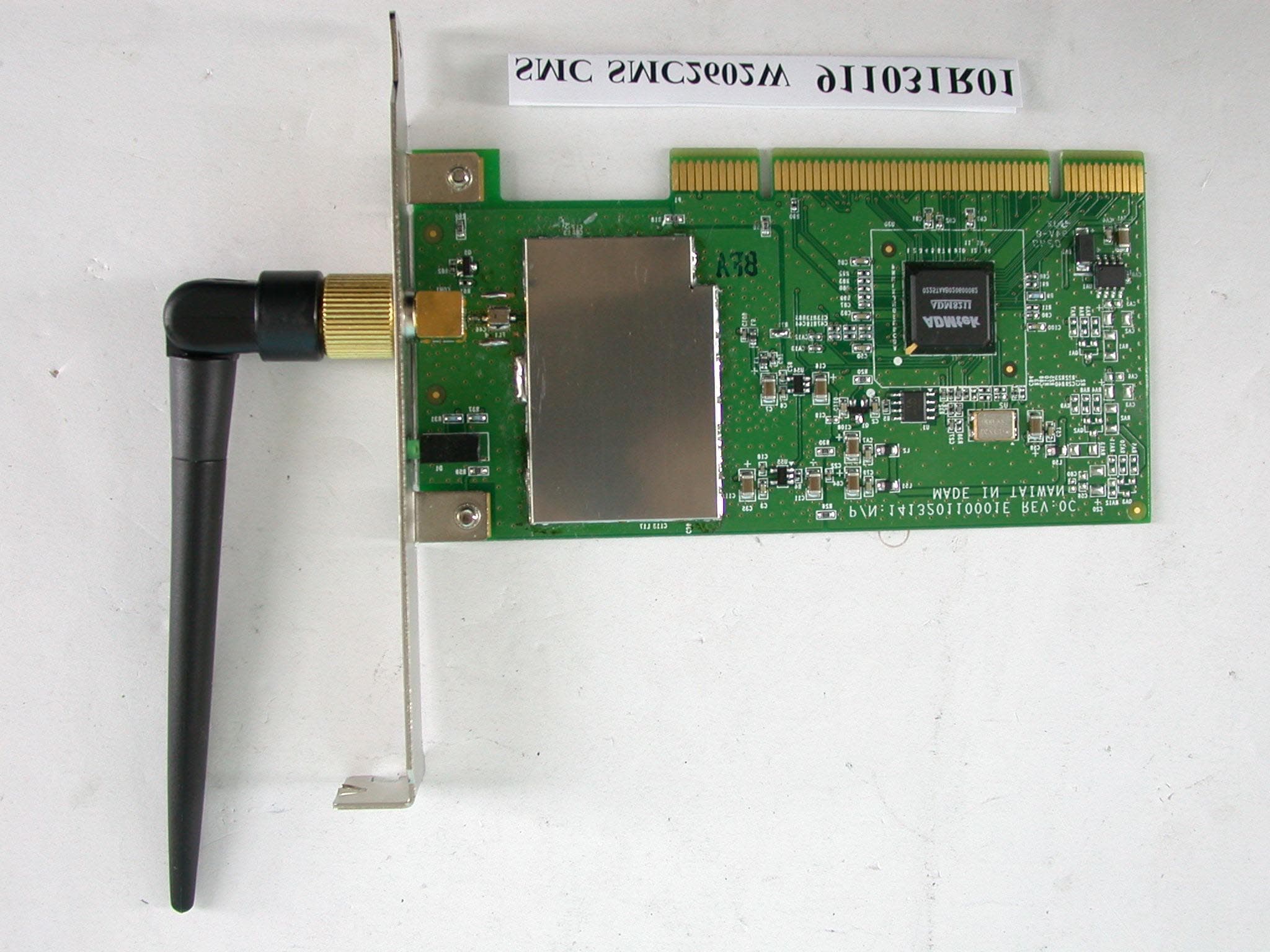
Click to zoom
Application Details
- Equipment Class
- DTS - Digital Transmission System
- Date of Grant
- Dec 09, 2002
- Application Purpose
- Original Equipment
- Date of Application
- Dec 09, 2002
- Equipment Note
- EZ Connect 11Mbps 2.4GHz Wireless PCI Card
- Frequency Range
- 2412.00000000 - 2462.00000000
- Company
- Accton Technology Corp
- Country
- Taiwan
Documents & Files
Document Text
Text extracted from the exhibit documents filed with the FCC. Open a document above to read the original.
Users Manual
EZ Connect ™ User Guide SMC2602W 2.4GHz 11 Mbps Wireless PCI Card 11 Mbps data rate – provides alternative to wired LANs that can dramatically cut costs Working range up to 160 m (528 ft) at 11 Mbps, 350 m (1155 ft) at 1 Mbps Seamless connectivity to wired Ethernet LANs augments existing networks quickly and easily DSSS technology provides robust, interference-resistant, and secure wireless connections Supports a wide range of operating systems (Windows 98/Me/2000/XP) Easy installation Removable external antenna 38 Tesla Irvine, CA 92618 Phone: (949) 679-8000 EZ Connect 2.4 GHz 11 Mbps Wireless PCI Card User Guide The easy way to make all your network connections October 2002 Revision Number: F1.0 Pub No: 150000013300E R01 Copyright Information furnished by SMC Networks, Inc. (SMC) is believed to be accurate and reliable. However, no responsibility is assumed by SMC for its use, nor for any infringements of patents or other rights of third parties which may result from its use. No license is granted by implication or otherwise under any patent or patent rights of SMC. SMC reserves the right to change specifications at any time without notice. Copyright © 2002 by SMC Networks, Inc. 38 Tesla Irvine, CA 92618 All rights reserved. Printed in Taiwan Trademarks: SMC is a registered trademark; and EZ Connect is a trademark of SMC Networks, Inc. Other product and company names are trademarks or registered trademarks of their respective holders. i LIMITED WARRANTY Limited Warranty Statement: SMC Networks, Inc. (“SMC”) warrants its products to be free from defects in workmanship and materials, under normal use and service, for the applicable warranty term. All SMC products carry a standard 90-day limited warranty from the date of purchase from SMC or its Authorized Reseller. SMC may, at its own discretion, repair or replace any product not operating as warranted with a similar or functionally equivalent product, during the applicable warranty term. SMC will endeavor to repair or replace any product returned under warranty within 30 days of receipt of the product. The standard limited warranty can be upgraded to a Limited Lifetime* warranty by registering new products within 30 days of purchase from SMC or its Authorized Reseller. Registration can be accomplished via the enclosed product registration card or online via the SMC Web site. Failure to register will not affect the standard limited warranty. The Limited Lifetime warranty covers a product during the Life of that Product, which is defined as the period of time during which the product is an “Active” SMC product. A product is considered to be “Active” while it is listed on the current SMC price list. As new technologies emerge, older technologies become obsolete and SMC will, at its discretion, replace an older product in its product line with one that incorporates these newer technologies. At that point, the obsolete product is discontinued and is no longer an “Active” SMC product. A list of discontinued products with their respective dates of discontinuance can be found at: http://www.smc.com/index.cfm?action=customer_service_warranty. All products that are replaced become the property of SMC. Replacement products may be either new or reconditioned. Any replaced or repaired product carries either a 30-day limited warranty or the remainder of the initial warranty, whichever is longer. SMC is not responsible for any custom software or firmware, configuration information, or memory data of Customer contained in, stored on, or integrated with any products returned to SMC pursuant to any warranty. Products returned to SMC should have any customer-installed accessory or add-on components, such as expansion modules, removed prior to returning the product for replacement. SMC is not responsible for these items if they are returned with the product. Customers must contact SMC for a Return Material Authorization number prior to returning any product to SMC. Proof of purchase may be required. Any product returned to SMC without a valid Return Material Authorization (RMA) number clearly marked on the outside of the package will be returned to customer at customer’s expense. For warranty claims within North America, please call our toll-free customer support number at (800) 762-4968. Customers are responsible for all shipping charges from their facility to SMC. SMC is responsible for return shipping charges from SMC to customer. LIMITED WARRANTY ii WARRANTIES EXCLUSIVE: IF AN SMC PRODUCT DOES NOT OPERATE AS WARRANTED ABOVE, CUSTOMER’S SOLE REMEDY SHALL BE REPAIR OR REPLACEMENT OF THE PRODUCT IN QUESTION, AT SMC’S OPTION. THE FOREGOING WARRANTIES AND REMEDIES ARE EXCLUSIVE AND ARE IN LIEU OF ALL OTHER WARRANTIES OR CONDITIONS, EXPRESS OR IMPLIED, EITHER IN FACT OR BY OPERATION OF LAW, STATUTORY OR OTHERWISE, INCLUDING WARRANTIES OR CONDITIONS OF MERCHANTABILITY AND FITNESS FOR A PARTICULAR PURPOSE. SMC NEITHER ASSUMES NOR AUTHORIZES ANY OTHER PERSON TO ASSUME FOR IT ANY OTHER LIABILITY IN CONNECTION WITH THE SALE, INSTALLATION, MAINTENANCE OR USE OF ITS PRODUCTS. SMC SHALL NOT BE LIABLE UNDER THIS WARRANTY IF ITS TESTING AND EXAMINATION DISCLOSE THE ALLEGED DEFECT IN THE PRODUCT DOES NOT EXIST OR WAS CAUSED BY CUSTOMER’S OR ANY THIRD PERSON’S MISUSE, NEGLECT, IMPROPER INSTALLATION OR TESTING, UNAUTHORIZED ATTEMPTS TO REPAIR, OR ANY OTHER CAUSE BEYOND THE RANGE OF THE INTENDED USE, OR BY ACCIDENT, FIRE, LIGHTNING, OR OTHER HAZARD. LIMITATION OF LIABILITY: IN NO EVENT, WHETHER BASED IN CONTRACT OR TORT (INCLUDING NEGLIGENCE), SHALL SMC BE LIABLE FOR INCIDENTAL, CONSEQUENTIAL, INDIRECT, SPECIAL, OR PUNITIVE DAMAGES OF ANY KIND, OR FOR LOSS OF REVENUE, LOSS OF BUSINESS, OR OTHER FINANCIAL LOSS ARISING OUT OF OR IN CONNECTION WITH THE SALE, INSTALLATION, MAINTENANCE, USE, PERFORMANCE, FAILURE, OR INTERRUPTION OF ITS PRODUCTS, EVEN IF SMC OR ITS AUTHORIZED RESELLER HAS BEEN ADVISED OF THE POSSIBILITY OF SUCH DAMAGES. SOME STATES DO NOT ALLOW THE EXCLU…
Text truncated - open the document above for the full version.
External Photos
Page 1 ANNEX PHOTOGRAPHS OF EUT
ID Label/Location Info
For FCC ID Label Location
ID Label/Location Info
geprufte Sicherhelt .. .. Rheinland Product Safety TUV IEC 60601-1 SMC2602W US V.2 91 10 29 R01 146000023500E +0.5mm -0.5mm Metalized Word:black background:silver UL approve-Acrylic Sylin 50# R1.5mm*4 Made in XXXXXX XX 146000023500E R01 XX IC ID:XXXXXXXXXXXXXX FCC ID:HED WN3201D ACC 50 3 0 Model :SMC2602W V.2 662968 701142 Part No.:99-012084-121 Sub-Assy No.:91-012084-121 EZ Connect 2.4GHZ 11Mbps Wireless PCI Card
Internal Photos
Page 2 Page 3
Operational Description
FCC ID: HEDWN3201DACC ADT No.911031R01 Operational Description The transmitter of the EUT (EZ Connect 2.4GHz 11Mbps Wireless PCI Card) is powered by host equipment via a PCI slot interface. The antenna is Dipole antenna, and the antenna connector type is Reversed SMA. Under normal use condition, the user has to keep at least 20cm separation distance between radiator and the body of the user. The other instruction, please have a look at the users manual. DSSS Information This device is Direct Sequence Spread Spectrum, the data is mixed by pseudorandom code which is an orthogonal code. The mixed data is digital modulated by BPSK and QPSK technique depends on the data rates. The CCK coding is applied for increasing the data rate, and also the processing gain will be increased. The bit rates are 1,2,5.5,11Mbps, the symbol rates are 1,1,1.375,1.375Mbps, the chip rates are always 11Mbps. So, the Chip/symbol is 11,11,8 and 8 respectively. Although is higher bit rate, the processing gain is lower than 10, but the CCK coding used in higher bit rate will provide 2.2dB coding gain.
RF Exposure Info
FCC ID: HEDWN3201DACC ADT No.: 911031R01 FCC TEST REPORT REPORT NO.: RF911031R01 MODEL NO.: SMC2602W ACCORDING: FCC Guidelines for Human Exposure IEEE C95.1 APPLICANT: ACCTON TECHNOLOGY CORPORATION ADDRESS: No.1, Creation Rd., III, Science-Based Industrial Park, Hsinchu, Taiwan, R.O.C. ISSUED BY: Advance Data Technology Corporation LAB LOCATION: 47 14th Lin, Chiapau Tsun, Linko, Taipei, Taiwan, R.O.C. 0528 ILAC MRA Lab Code: 200102-0 FCC ID: HEDWN3201DACC ADT No.: 911031R01 RF Exposure Measurement (Mobile Device) 1. Introduction 2.4 GHz frequency band is regarded specially as a dangerous band for its heating harmfulness to the human body. That’s why microwave oven is operating in this frequency band. The manufacturer whose product is working in this frequency band is obligatory to prove the harmfulness of his product. In this document, we try to prove the safety of radiation harmfulness to the human body for our product. The limit for Maximum Permissible Exposure (MPE) specified in FCC 1.1310 is followed. The Gain of the antenna used in this product is measured in a Fully Anechoic Chamber (FAC), and the maximum total power input to the antenna is measured. Through the Friis transmission formula and the maximum gain of the antenna, we can calculate the distance, away from the product, where the limit of MPE is reached. 2. Classification The antenna of the product, under normal use condition, is at least 20 cm away from the body of the user. Warning statement for keeping 20 cm separation distance and the prohibition of operating next to a person has been printed on the users manual. So, this product is classified as the Mobile Device. 3. RF Exposure Limit According to FCC 1.1310: The criteria listed in the following table shall be used to evaluate the environmental impact of human exposure to radio-frequency (RF) radiation as specified in 1.1307(b). FCC ID: HEDWN3201DACC ADT No.: 911031R01 LIMITS FOR MAXIMUM PERMISSIBLE EXPOSURE (MPE) Frequency Range (MHz) Electric Field Strength (V/m) Magnetic Field Strength (A/m) Power Density (mW/cm 2 ) Average Time (minutes) (A)Limits For Occupational / Control Exposures 30-30061.40.1631.06 300-1500......F/3006 1500-100,000......56 (B)Limits For General Population / Uncontrolled Exposure 30-30027.50.0730.230 300-1500......F/150030 1500-100,000......1.030 F = Frequency in MHz 4. Friis Formula Friis transmission formula : Pd = (Pout*G) / (4*pi*r 2 ) where Pd = power density in mW/cm 2 Pout = output power to antenna in mW G = gain of antenna in linear scale Pi = 3.1416 R = distance between observation point and center of the radiator in cm Pd is the limit of MPE, 1 mW/cm 2 . If we know the maximum Gain of the antenna and the total power input to the antenna, through the calculation, we will know the distance r where the MPE limit is reached. Ref. : David K. Cheng, Field and Wave Electromagnetics, Second Edition, Page 640, Eq. (11-133). 5. EUT Operating condition The software provided by Manufacturer enabled the EUT to transmit and receive data at lowest, middle and highest channel individually. FCC ID: HEDWN3201DACC ADT No.: 911031R01 6. Test Results 6.1 Antenna Gain The maximum Gain measured in Fully Anechoic Chamber is 1.5 dBi only. 6.2 Output Power Into Antenna & RF Exposure Distance : CHANNEL CHANNEL FREQUENCY (MHz) OUTPUT POWER TO ANTENNA (mW) MINIMUM ALLOWABLE DISTANCE ( r ) FROM SKIN (Centi-Meter) 1241230.621.86 6243732.731.92 11246231.771.89 The minimum allowable distance is very close to the enclosure of the antenna. So, the user has no need to worry about the harmfulness of radiation. But it is recommended to always keep, at least, 20cm separation distance with the antenna.
Test Report
FCC ID: HEDWN3201DACC Report No.: RF911031R011Issued: Dec. 9, 2002 FCC TEST REPORT REPORT NO.: RF911031R01 MODEL NO.: SMC2602W (Brand: SMC) OEM MODEL NO.: WN3201D (Brand: Accton) RECEIVED: Oct. 31, 2002 TESTED: Nov. 13 ~ Nov. 21, 2002 APPLICANT: ACCTON TECHNOLOGY CORPORATION ADDRESS: No. 1, Creation Rd., III, Science-Based Industrial Park, Hsinchu, Taiwan, R.O.C. ISSUED BY: Advance Data Technology Corporation LAB LOCATION: 47 14th Lin, Chiapau Tsun, Linko, Taipei, Taiwan, R.O.C. This test report consists of 48 pages in total. It may be duplicated completely for legal use with the approval of the applicant. It should not be reproduced except in full, without the written approval of our laboratory. The client should not use it to claim product endorsement by CNLA, NVLAP or any government agencies. The test results in the report only apply to the tested sample. 0528 ILAC MRA Lab Code: 200102-0 FCC ID: HEDWN3201DACC Report No.: RF911031R012Issued: Dec. 9, 2002 Table of Contents 1CERTIFICATION.....................................................................................4 2SUMMARY OF TEST RESULTS...............................................................5 3GENERAL INFORMATION.......................................................................6 3.1GENERAL DESCRIPTION OF EUT..........................................................6 3.2DESCRIPTION OF TEST MODES............................................................7 3.3GENERAL DESCRIPTION OF APPLIED STANDARDS.............................7 3.4DESCRIPTION OF SUPPORT UNITS......................................................8 4TEST TYPES AND RESULTS..................................................................9 4.1CONDUCTED EMISSION MEASUREMENT.............................................9 4.1.1LIMITS OF CONDUCTED EMISSION MEASUREMENT............................9 4.1.2TEST INSTRUMENTS.............................................................................9 4.1.3TEST PROCEDURES............................................................................10 4.1.4DEVIATION FROM TEST STANDARD....................................................10 4.1.5TEST SETUP.........................................................................................11 4.1.6EUT OPERATING CONDITIONS.............................................................11 4.1.7TEST RESULTS....................................................................................12 4.2RADIATED EMISSION MEASUREMENT................................................18 4.2.1LIMITS OF RADIATED EMISSION MEASUREMENT...............................18 4.2.2TEST INSTRUMENTS...........................................................................19 4.2.3TEST PROCEDURES............................................................................20 4.2.4DEVIATION FROM TEST STANDARD....................................................20 4.2.5TEST SETUP........................................................................................21 4.2.6EUT OPERATING CONDITIONS............................................................21 4.2.7TEST RESULTS....................................................................................22 4.36dB BANDWIDTH MEASUREMENT.......................................................26 4.3.1LIMITS OF 6dB BANDWIDTH MEASUREMENT.....................................26 4.3.2TEST INSTRUMENTS...........................................................................26 4.3.3TEST PROCEDURE..............................................................................27 4.3.4DEVIATION FROM TEST STANDARD....................................................27 4.3.5TEST SETUP........................................................................................27 4.3.6EUT OPERATING CONDITIONS............................................................27 4.3.7TEST RESULTS....................................................................................28 4.4MAXIMUM PEAK OUTPUT POWER.......................................................32 4.4.1LIMITS OF MAXIMUM PEAK OUTPUT POWER MEASUREMENT..........32 4.4.2TEST INSTRUMENTS...........................................................................32 FCC ID: HEDWN3201DACC Report No.: RF911031R013Issued: Dec. 9, 2002 4.4.3TEST PROCEDURES............................................................................33 4.4.4DEVIATION FROM TEST STANDARD....................................................33 4.4.5TEST SETUP........................................................................................33 4.4.6EUT OPERATING CONDITIONS............................................................33 4.4.7TEST RESULTS....................................................................................34 4.5POWER SPECTRAL DENSITY MEASUREMENT...................................35 4.5.1LIMITS OF POWER SPECTRAL DENSITY MEASUREMENT..................35 4.5.2TEST INSTRUMENTS...........................................................................35 4.5.3TEST PROCEDURE..............................................................................36 4.5.4DEVIATION FROM TEST STANDARD....................................................36 4.5.5TEST SETUP........................................................................................36 4.5.6EUT OPERATING CONDITIONS............................................................36 4.5.7TEST RESULTS....................................................................................37 4.6BAND EDGES MEASUREMENT............................................................41 4.6.1LIMITS OF BAND EDGES MEASUREMENT...........................................41 4.6.2TEST INSTRUMENTS...........................................................................41 4.6.3TEST PROCEDURE..............................................................................41 4.6.4DEVIATION FROM TEST STANDARD....................................................41 4.6.5EUT OPERATING CONDITION.....................…
Text truncated - open the document above for the full version.
Test Setup Photos
FCC ID: HEDWN3201DACC Report No.: RF911031R0146Issued: Dec. 9, 2002 5 PHOTOGRAPHS OF THE TEST CONFIGURATION CONDUCTED EMISSION TEST FCC ID: HEDWN3201DACC Report No.: RF911031R0147Issued: Dec. 9, 2002 RADIATED EMISSION TEST
Contact Information
Applicant
Abby Wei(Manager)
Technical Contact
Advance Data Technology CorporationAlan Lane
[email protected]+886 3 327 0910
13-1, Lane 19, WenShan 3rd St · Taoyuan · Taiwan
Test Firm
Bureau Veritas CPS (H.K.) Ltd. Taoyuan BranchRichard Chen
Technical Specifications
| # | Rule Parts | Frequency Range | Power Output |
|---|---|---|---|
| 1 | 15C | 2.41 GHz - 2.46 GHz | 33.00 mW |
Other Applications from Accton Technology Corp

HEDEAP115
Jan 27, 2026Wi-Fi 7 AP
Equipment Class
NII - Unlicensed National Information Infrastructure TX
HEDEAP112
Oct 13, 2024Wi-Fi 6 IoT Gateway
Equipment Class
DTS - Digital Transmission System
HEDEAP111
Mar 17, 2024Wi-Fi 6 Access Point
Equipment Class
DTS - Digital Transmission System
HEDOAP101E
Oct 24, 2023Outdoor Access Point
Equipment Class
DTS - Digital Transmission System
HEDEAP104
Dec 14, 2022Indoor Wall Plate WiFi 6 Access Point
Equipment Class
DTS - Digital Transmission System