HEDWN3304B17PCMCIA Wireless Card
Accton Technology Corp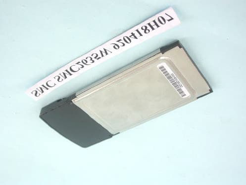
Click to zoom
Application Details
- Equipment Class
- DTS - Digital Transmission System
- Date of Grant
- May 04, 2003
- Application Purpose
- Original Equipment
- Date of Application
- May 01, 2003
- Equipment Note
- PCMCIA Wireless Card
- Frequency Range
- 2412.00000000 - 2462.00000000
- Company
- Accton Technology Corp
- Country
- Taiwan
Documents & Files
Document Text
Text extracted from the exhibit documents filed with the FCC. Open a document above to read the original.
Users Manual
SMC2635W 38 Tesla Irvine, CA 92618 Phone: (949) 679-8000 EZ Connect 2.4GHz 11 Mbps Wireless Cardbus Adapter User Guide The easy way to make all your network connections April 2003 Revision Number: F1.0 Pub No: 150000021200E R01 Copyright Information furnished by SMC Networks, Inc. (SMC) is believed to be accurate and reliable. However, no responsibility is assumed by SMC for its use, nor for any infringements of patents or other rights of third parties which may result from its use. No license is granted by implication or otherwise under any patent or patent rights of SMC. SMC reserves the right to change specifications at any time without notice. Copyright © 2003 by SMC Networks, Inc. 38 Tesla Irvine, CA 92618 All rights reserved. Printed in Taiwan Trademarks: SMC is a registered trademark; and EZ Connect is a trademark of SMC Networks, Inc. Other product and company names are trademarks or registered trademarks of their respective holders. i COMPLIANCES Federal Communication Commission Interference Statement This equipment has been tested and found to comply with the limits for a Class B digital device, pursuant to Part 15 of the FCC Rules. These limits are designed to provide reasonable protection against harmful interference in a residential installation. This equipment generates, uses and can radiate radio frequency energy and, if not installed and used in accordance with the instructions, may cause harmful interference to radio communications. However, there is no guarantee that interference will not occur in a particular installation. If this equipment does cause harmful interference to radio or television reception, which can be determined by turning the equipment off and on, the user is encouraged to try to correct the interference by one of the following measures: • Reorient or relocate the receiving antenna • Increase the separation between the equipment and receiver • Connect the equipment into an outlet on a circuit different from that to which the receiver is connected • Consult the dealer or an experienced radio/TV technician for help FCC Caution: To assure continued compliance, (example - use only shielded interface cables when connecting to computer or peripheral devices) any changes or modifications not expressly approved by the party responsible for compliance could void the user's authority to operate this equipment. This device complies with Part 15 of the FCC Rules. Operation is subject to the following two conditions: (1) This device may not cause harmful interference, and (2) this device must accept any interference received, including interference that may cause undesired operation. IMPORTANT NOTE: FCC Radiation Exposure Statement: This equipment complies with FCC radiation exposure limits set forth for an uncontrolled environment. This transmitter must not be co-located or operating in conjunction with any other antenna or transmitter. COMPLIANCES ii Industry Canada - Class B This digital apparatus does not exceed the Class B limits for radio noise emissions from digital apparatus as set out in the interference-causing equipment standard entitled “Digital Apparatus,” ICES-003 of Industry Canada. Cet appareil numérique respecte les limites de bruits radioélectriques applicables aux appareils numériques de Classe B prescrites dans la norme sur le matérial brouilleur: “Appareils Numériques,” NMB-003 édictée par l’Industrie. EC Conformance Declaration - Class B SMC contact for these products in Europe is: SMC Networks Europe, Edificio Conata II, Calle Fructuós Gelabert 6-8, 2 o , 4 a , 08970 - Sant Joan Despí, Barcelona, Spain. This information technology equipment complies with the requirements of the Council Directive 89/336/EEC on the Approximation of the laws of the Member States relating to Electromagnetic Compatibility and 73/23/EEC for electrical equipment used within certain voltage limits and the Amendment Directive 93/68/ EEC. For the evaluation of the compliance with these Directives, the following standards were applied: RFI Emission:• Limit class B according to EN 55022:1998, IEC 60601-1-2 (EMC, medical) • Limit class B for harmonic current emission according to EN 61000-3-2/1995 • Limitation of voltage fluctuation and flicker in low-voltage supply system according to EN 61000-3-3/1995 Immunity:• Product family standard according to EN 55024:1998 • Electrostatic Discharge according to EN 61000-4-2:1995 (Contact Discharge: ±4 kV, Air Discharge: ±8 kV) • Radio-frequency electromagnetic field according to EN 61000-4-3:1996 (80 - 1000 MHz with 1 kHz AM 80% Modulation: 3 V/m) • Electrical fast transient/burst according to EN 61000-4-4:1995 (AC/DC power supply: ±1 kV, Data/Signal lines: ±0.5 kV) • Surge immunity test according to EN 61000-4-5:1995 (AC/DC Line to Line: ±1 kV, AC/DC Line to Earth: ±2 kV) COMPLIANCES iii Safety Compliance Wichtige Sicherheitshinweise (Germany) 1. Bitte lesen Sie diese Hinweise sorgfältig durch. 2. Heben Sie diese Anleitung für den späteren Gebrauch auf. 3. Vor jedem Reinigen ist das Gerät vom Stromnetz zu trennen. Verwenden Sie keine Flüssigoder Aerosolreiniger. Am besten eignet sich ein angefeuchtetes Tuch zur Reinigung. 4. Die Netzanschlu ßsteckdose soll nahe dem Gerät angebracht und leicht zugänglich sein. 5. Das Gerät ist vor Feuchtigkeit zu schützen. 6. Bei der Aufstellung des Gerätes ist auf sicheren Stand zu achten. Ein Kippen oder Fallen könnte Beschädigungen hervorrufen. 7. Die Belüftungsöffnungen dienen der Luftzirkulation, die das Gerät vor Überhitzung schützt. Sorgen Sie dafür, daß diese Öffnungen nicht abgedeckt werden. 8. Beachten Sie beim Anschluß an das Stromnetz die Anschlußwerte. 9. Verlegen Sie die Netzanschlußleitung so, daß niemand darüber fallen kann. Es sollte auch nichts auf der Leitung abgestellt werden. 10. Alle Hinweise und Warnungen, die sich am Gerät befinden, sind zu beachten. 11. Wird das Gerät über einen längeren Zeitraum nicht benutzt, sollten Sie es vom Stromnetz trennen. Somit wird im Falle ein…
Text truncated - open the document above for the full version.
External Photos
Page 1 CONSTRUCTION PHOTOS OF EUT
ID Label/Location Info
(Fig. 1) FCC ID: HEDWN3304B17 FCC LABEL LOCATION The label will be permanently affixed at a conspicuous location on the device. Label
ID Label/Location Info
xxxxxx SMC2635W 92 04 16 R01 146000024800E +0.2mm -0.4mm White mylor+pp Word:black background:white UL approve-Acrylic Sylin R2mm*4 Made in XXXXXX XX 146000024800E R01 XX 4 6 . 0 m m 41.0 mm xxxxxxxx FCC ID:xxxxxxxxxxxx Canada ID:xxxxx-xxxxxxxx US upc code 30*10mm
Internal Photos
Page 1 CONSTRUCTION PHOTOS OF EUT Page 2 Page 3
Operational Description
FCC ID: HEDWN3304B17 ADT No.920418H07 Operational Description The transmitter of the EUT is powered by host equipment. The antenna is Printed Antenna. There is no antenna connector. The other instruction, please have a look at the users manual. DSSS Information This device is Direct Sequence Spread Spectrum, the data is mixed by pseudorandom code which is an orthogonal code. The mixed data is digital modulated by BPSK and QPSK technique depends on the data rates. The CCK coding is applied for increasing the data rate, and also the processing gain will be increased. The bit rates are 1,2,5.5,11Mbps, the symbol rates are 1,1,1.375,1.375Mbps, the chip rates are always 11Mbps. So, the Chip/symbol is 11,11,8 and 8 respectively. Although is higher bit rate, the processing gain is lower than 10, but the CCK coding used in higher bit rate will provide 2.2dB coding gain.
RF Exposure Info
FCC ID: HEDWN3304B17 Report No.: SA920418H071Issued: April 30 th 2003 SAR TEST REPORT REPORT NO.: SA920418H07 MODEL NO.: SMC2635W (for Brand: SMC) WN3304B (for Brand: Accton) RECEIVED: April 18, 2003 TESTED: April 28, 2003 APPLICANT: Accton Technology Corporation. ADDRESS: No.1, Creation Rd. III, Science-based Industrial Park, Hsinchu, Taiwan, ROC ISSUED BY: Advance Data Technology Corporation LAB LOCATION: 47 14th Lin, Chiapau Tsun, Linko, Taipei, Taiwan, R.O.C. This test report consists of 15 pages in total except Appendix. It may be duplicated completely for legal use with the approval of the applicant. It should not be reproduced except in full, without the written approval of our laboratory. The client should not use it to claim product endorsement by CNLA, NVLAP or any government agencies. The test results in the report only apply to the tested sample. FCC ID: HEDWN3304B17 Report No.: SA920418H072Issued: April 30 th 2003 Table of Contents 1.CERTIFICATION.........................................................................................................3 2.GENERAL INFORMATION..........................................................................................4 2.1GENERAL DESCRIPTION OF EUT.............................................................................4 2.2GENERAL DESCRIPTION OF APPLIED STANDARDS.................................................4 2.3GENERAL INOFRMATION OF THE SAR SYSTEM.......................................................4 2.4GENERAL DESCRIPTION OF THE PROBE SCAN RULE.............................................4 3.DESCRIPTION OF TEST MODES AND CONFIGURATIONS.........................................4 4.DESCRIPTION OF SUPPORT UNITS..........................................................................4 5.TEST RESULTS..........................................................................................................4 5.1TEST PROCEDURES.................................................................................................4 5.2MEASURED SAR RESULT..........................................................................................4 5.3SAR LIMITS................................................................................................................4 5.4EUT CONDUCTED POWER VARIATION.....................................................................4 5.5TISSUE......................................................................................................................4 5.6TEST EQUIPMENT FOR TISSUE PROPERTY.............................................................4 6.SYSTEM VALIDATION................................................................................................4 7.MEASUREMENT UNCERTAINTIES.............................................................................4 8.INFORMATION ON THE TESTING LABORATORIES....................................................4 APPENDIX A: TEST CONFIGURATIONS AND TEST DATA APPENDIX B: ADT SAR MEASUREMENT SYSTEM APPENDIX C: PHOTOGRAPHS OF SYSTEM VALIDATION APPENDIX D: SYSTEM CERTIFICATE & CALIBRATION FCC ID: HEDWN3304B17 Report No.: SA920418H073Issued: April 30 th 2003 1. CERTIFICATION PRODUCT : PCMCIA Wireless Card MODEL NO. : SMC2635W (for Brand: SMC) WN3304B (for Brand: Accton) APPLICANT : Accton Technology Corporation STANDARDS : 47 CFR Part 2 (Section 2.1093), FCC OET Bulletin 65, Supplement C (01-01), RSS-102 We, Advance Data Technology Corporation, hereby certify that one sample of the designation has been tested in our facility on 28 th April 2003. The test record, data evaluation and Equipment Under Test (EUT) configurations represented herein are true and accurate, and it was tested according to the standards listed above. This device was found to be in compliance with the Specific Absorption Rate (SAR) requirement specified in FCC part 2.1093 under General Population / Uncontrolled Exposure condition. FCC ID: HEDWN3304B17 Report No.: SA920418H074Issued: April 30 th 2003 2. GENERAL INFORMATION 2.1 GENERAL DESCRIPTION OF EUT PRODUCT PCMCIA Wireless Card MODEL NO. SMC2635W, WN3304B POWER SUPPLY 3.3VDC powered by host equipment CLASSIFICATION Portable device, production unit MODULATION TYPE BPSK, QPSK, CCK RADIO TECHNOLOGY DSSS TRANSFER RATE 1~11Mbps FREQUENCY RANGE 2412MHz ~ 2462MHz NUMBER OF CHANNEL 11 CONDUCTED OUTPUT POWER 72.77mW ANTENNA TYPE Internal Printed Antenna PEAK SAR 0.326W/kg DATA CABLE NA I/O PORTS PCMCIA ASSOCIATED DEVICES NA NOTE: Two models are identical except for their model number. 2.2 GENERAL DESCRIPTION OF APPLIED STANDARDS According to the specifications of the manufacturer, this product must comply with the requirements of the following standards: FCC 47 CFR Part 2 (2.1093) FCC OET Bulletin 65, Supplement C (01- 01) RSS-102 All tests have been performed and recorded as per the above standards. FCC ID: HEDWN3304B17 Report No.: SA920418H075Issued: April 30 th 2003 2.3 GENERAL INOFRMATION OF THE SAR SYSTEM DASY4 (software 4.1, build 33) consists of high precision robtics system, probe alignment sensor, phantom, robot controller, controlled PC and near-field probe. The robot includes six axis that can move to the precision position of the DASY4 software defined. The DASY4 software can define the area which is detected by the probe. The robot is connected to controlled box. Controlled PC is connected to the controlled robot box. The DAE includes amplifier, signal multiplexing, AD converter, offset measurement, surface detection. It is connected to the Electro-optical coupler (ECO). The ECO performs the conversion form the optical into digital electric signal of the DAE and transfers data to the PC. ET3DV6 ISOTROPIC E-FIELD PROBE Construction Symmetrical design with triangular core. Built-in optical fiber for surface detection system. Built-in shielding against static charges. PEEK enclosure material (resistant to organic solvents, e.g., glycolether). Calibration Basic Broad Band Calibration in air: 10-2500 MHz Conversion Factors (C…
Text truncated - open the document above for the full version.
RF Exposure Info
APPENDIX A: TEST CONFIGURATIONS AND TEST DATA A1: TEST CONFIGURATION Mode 1 Mode 2 Mode 3 EUT Photo Date/Time: 04/28/03 15:48:18 Test Laboratory: Advance Data Technology Corporation SMC2635W Mode 1 channel 01 DUT: PCMCIA Wireless Card ; Type: SMC2635W Communication System: 802.11b ; Frequency: 2412 MHz; Duty Cycle: 1:1; Modulation type: DSSS Medium: MSL2450 (σ = 1.93 mho/m, ε r = 52.2, ρ = 1000 kg/m 3 ) ; Liquid level : 151mm Phantom section: Flat Section ; Separation distance : 0mm(The bottom of the card to the Phantom) Antenna type : Internal Antenna ; Air tempreature : 23.0 degrees ; Liquid temperature : 22.2 degrees DASY4 Configuration: - Probe: ET3DV6 - SN1687; ConvF(4.4, 4.4, 4.4); Calibrated: 2002/9/28 - Sensor-Surface: 4mm (Mechanical And Optical Surface Detection) - Electronics: DAE3 Sn510; Calibrated: DAE not calibrated - Phantom: SAM Twin Phantom V4.0; Type: QD 000 P40 CA; Serial: TP-1150 - Measurement SW: DASY4, V4.1 Build 33; Postprocessing SW: SEMCAD, V1.6 Build 109 System testing procedure/Area Scan (5x7x1): Measurement grid: dx=20mm, dy=20mm System testing procedure/Zoon Scan (5x5x7)/Cube 0: Measurement grid: dx=8mm, dy=8mm, dz=5mm Reference Value = 7.84 V/m Peak SAR = 0.347 W/kg SAR(1 g) = 0.206 mW/g; SAR(10 g) = 0.0971 mW/g Power Drift = -0.2 dB A2: TEST DATA Date/Time: 04/28/03 16:09:42 Test Laboratory: Advance Data Technology Corporation SMC2635W Mode 1 channel 06 DUT: PCMCIA Wireless Card ; Type: SMC2635W Communication System: 802.11b ; Frequency: 2437 MHz; Duty Cycle: 1:1; Modulation type: DSSS Medium: MSL2450 (σ = 1.95 mho/m, ε r = 52.18, ρ = 1000 kg/m 3 ) ; Liquid level : 151mm Phantom section: Flat Section ; Separation distance : 0mm(The bottom of the card to the Phantom) Antenna type : Internal Antenna ; Air tempreature : 23.0 degrees ; Liquid temperature : 22.2 degrees DASY4 Configuration: - Probe: ET3DV6 - SN1687; ConvF(4.4, 4.4, 4.4); Calibrated: 2002/9/28 - Sensor-Surface: 4mm (Mechanical And Optical Surface Detection) - Electronics: DAE3 Sn510; Calibrated: DAE not calibrated - Phantom: SAM Twin Phantom V4.0; Type: QD 000 P40 CA; Serial: TP-1150 - Measurement SW: DASY4, V4.1 Build 33; Postprocessing SW: SEMCAD, V1.6 Build 109 System testing procedure/Area Scan (5x7x1): Measurement grid: dx=20mm, dy=20mm System testing procedure/Zoon Scan (5x5x7)/Cube 0: Measurement grid: dx=8mm, dy=8mm, dz=5mm Reference Value = 6.61 V/m Peak SAR = 0.332 W/kg SAR(1 g) = 0.194 mW/g; SAR(10 g) = 0.0914 mW/g Power Drift = -0.2 dB Date/Time: 04/28/03 16:28:32 Test Laboratory: Advance Data Technology Corporation SMC2635W Mode 1 channel 11 DUT: PCMCIA Wireless Card ; Type: SMC2635W Communication System: 802.11b ; Frequency: 2462 MHz; Duty Cycle: 1:1; Modulation type: DSSS Medium: MSL2450 (σ = 1.99 mho/m, ε r = 52.1, ρ = 1000 kg/m 3 ) ; Liquid level : 151mm Phantom section: Flat Section ; Separation distance : 0mm(The bottom of the card to the Phantom) Antenna type : Internal Antenna ; Air tempreature : 23.0 degrees ; Liquid temperature : 22.2 degrees DASY4 Configuration: - Probe: ET3DV6 - SN1687; ConvF(4.4, 4.4, 4.4); Calibrated: 2002/9/28 - Sensor-Surface: 4mm (Mechanical And Optical Surface Detection) - Electronics: DAE3 Sn510; Calibrated: DAE not calibrated - Phantom: SAM Twin Phantom V4.0; Type: QD 000 P40 CA; Serial: TP-1150 - Measurement SW: DASY4, V4.1 Build 33; Postprocessing SW: SEMCAD, V1.6 Build 109 System testing procedure/Area Scan (5x7x1): Measurement grid: dx=20mm, dy=20mm System testing procedure/Zoon Scan (5x5x7)/Cube 0: Measurement grid: dx=8mm, dy=8mm, dz=5mm Reference Value = 10.1 V/m Peak SAR = 0.563 W/kg SAR(1 g) = 0.326 mW/g; SAR(10 g) = 0.153 mW/g Power Drift = -0.2 dB Date/Time: 04/28/03 15:30:10 Test Laboratory: Advance Data Technology Corporation SMC2635W Mode 2 channel 01 DUT: PCMCIA Wireless Card ; Type: SMC2635W Communication System: 802.11b ; Frequency: 2412 MHz; Duty Cycle: 1:1; Modulation type: DSSS Medium: MSL2450 (σ = 1.93 mho/m, ε r = 52.2, ρ = 1000 kg/m 3 ) ; Liquid level : 151mm Phantom section: Flat Section ; Separation distance : 15mm(The tip of the EUT to the Phantom) Antenna type : Internal Antenna ; Air tempreature : 23.0 degrees ; Liquid temperature : 22.2 degrees DASY4 Configuration: - Probe: ET3DV6 - SN1687; ConvF(4.4, 4.4, 4.4); Calibrated: 2002/9/28 - Sensor-Surface: 4mm (Mechanical And Optical Surface Detection) - Electronics: DAE3 Sn510; Calibrated: DAE not calibrated - Phantom: SAM Twin Phantom V4.0; Type: QD 000 P40 CA; Serial: TP-1150 - Measurement SW: DASY4, V4.1 Build 33; Postprocessing SW: SEMCAD, V1.6 Build 109 System testing procedure/Area Scan (5x5x1): Measurement grid: dx=20mm, dy=20mm System testing procedure/Zoon Scan (5x5x7)/Cube 0: Measurement grid: dx=8mm, dy=8mm, dz=5mm Reference Value = 2.52 V/m Peak SAR = 0.0683 W/kg SAR(1 g) = 0.0224 mW/g; SAR(10 g) = 0.011 mW/g Power Drift = -0.09 dB Date/Time: 04/28/03 13:51:34 Test Laboratory: Advance Data Technology Corporation SMC2635W Mode 2 channel 06 DUT: PCMCIA Wireless Card ; Type: SMC2635W Communication System: 802.11b ; Frequency: 2437 MHz; Duty Cycle: 1:1; Modulation type: DSSS Medium: MSL2450 (σ = 1.95 mho/m, ε r = 52.18, ρ = 1000 kg/m 3 ) ; Liquid level : 151mm Phantom section: Flat Section ; Separation distance : 15mm(The tip of the EUT to the Phantom) Antenna type : Internal Antenna ; Air tempreature : 23.0 degrees ; Liquid temperature : 22.2 degrees DASY4 Configuration: - Probe: ET3DV6 - SN1687; ConvF(4.4, 4.4, 4.4); Calibrated: 2002/9/28 - Sensor-Surface: 4mm (Mechanical And Optical Surface Detection) - Electronics: DAE3 Sn510; Calibrated: DAE not calibrated - Phantom: SAM Twin Phantom V4.0; Type: QD 000 P40 CA; Serial: TP-1150 - Measurement SW: DASY4, V4.1 Build 33; Postprocessing SW: SEMCAD, V1.6 Build 109 System testing procedure/Area Scan (5x5x1): Measurement grid: dx=20mm, dy=20mm System testing procedure/Zoon Scan (5x5x7)/Cube 0: Measurement grid: dx=8mm, dy=8mm, dz=5mm Reference Value = 2.63 V/m Peak SAR = 0.0543 W/kg SAR(1 g) = 0.026 mW/g; SAR(10 g) = 0.…
Text truncated - open the document above for the full version.
RF Exposure Info
APPENDIX C: PHOTOGRAPHS OF SYSTEM VALIDATION APPENDIX D: SYSTEM CERTIFICATE & CALIBRATION D1: SAM PHANTOM D2: 2450MHz SYSTEM VALIDATION DIPOLE D3: DOSIMETRIC E-FILED PROBE ET3DV6 SN:1687 June 5, 2002 Isotropy Error (Φ), θ = 0 ̊ ET3DV6 SN:1687 June 5, 2002 Frequency Response of E-Field (TEM – Cell:ifi110, Waveguide R22) Dynamic Range f (SAR brain ) (Waveguide R22) 1.E+7 1.E+6 1.E+5 1.E+4 1.E+3 1.E+2 1.E+1 1.E+0 mW/cm 3 not compensated compensated μ μμ μV 0.0001 0.001 0.01 0.1 1 10 100 ET3DV6 SN:1687September 28, 2002 Conversion Factor Assessment
Test Report
Report No.920418H07 ADT No.920418H07 1 The Measurement of Conducted Spurious Emissions CONDUCTED SPURIOUS EMISSIONS MEASUREMENT 1. LIMITS OF CONDUCTED SPURIOUS EMISSIONS EASUREMENT Below 20dB of the highest emission level of operating band (in 100KHz Resolution Bandwidth, see Section 15.247(c)). Emissions which fall in the restricted bands, as defined in Section 15.205(a), must also comply with the limits specified in Section 15.209(a) (see Section 15.205(c)). 2. TEST INSTRUMENTS Description & ManufacturerModel No.Serial No.Calibrated Until R&S SPECTRUM ANALYZERFSP1093.4495.30Dec. 19, 2003 NOTE: 1.The measurement uncertainty is less than +/- 2.6dB, which is calculated as per the NAMAS document NIS81. 2.The calibration interval of the above test instruments is 12 months and the calibrations are traceable to NML/ROC and NIST/USA. 3. TEST PROCEDURE The transmitter output was connected to the spectrum analyzer via a low lose cable. Set both RBW and VBW of spectrum analyzer to 100 kHz with suitable frequency span including 100 kHz bandwidth from band edge. The band edges was measured and recorded. Report No.920418H07 ADT No.920418H07 2 4. TEST SETUP 5. EUT OPERATING CONDITIONS The software provided by client to enable the EUT under transmission condition continuously at lowest, middle and highest channel frequencies individually. EUT SPECTRUM ANALYZER Report No.920418H07 ADT No.920418H07 3 TEST RESULTS The spectrum plots are attached on the following 2 pages. It shows compliance with the requirement in part 15.247(C),.15.205 and 15.209. Report No.920418H07 ADT No.920418H07 4 Ch1 Report No.920418H07 ADT No.920418H07 5 Ch1 Report No.920418H07 ADT No.920418H07 6 Ch11 Report No.920418H07 ADT No.920418H07 7 Ch11
Test Report
FCC ID: HEDWN3304B17 Report No.: RF920418H07 1 Issued: Apr. 30, 2003 ADT No. 920418H07 FCC TEST REPORT REPORT NO.: RF920418H07 MODEL NO.: SMC2635W, WN3304B RECEIVED: Apr. 18, 2003 TESTED: Apr. 21, 2003 APPLICANT: Accton Technology Corporation ADDRESS: No.1, Creation Rd. III, Science-based Industrial Park, Hsinchu, Taiwan, R.O.C ISSUED BY: Advance Data Technology Corporation LAB LOCATION: No. 81-1, Lu Liao Keng, 9 Ling, Wu Lung Tsuen, Chiung Lin Hsiang, Hsin Chu Hsien, Taiwan, R.O.C. This test report consists of 49 pages in total. It may be duplicated completely for legal use with the approval of the applicant. It should not be reproduced except in full, without the written approval of our laboratory. The client should not use it to claim product endorsement by CNLA, NVLAP or any government agencies. The test results in the report only apply to the tested sample. Lab Code: 200376-0 FCC ID: HEDWN3304B17 Report No.: RF920418H07 2 Issued: Apr. 30, 2003 ADT No. 920418H07 Table of Contents 1 CERTIFICATION.....................................................................................................4 2 SUMMARY OF TEST RESULTS..........................................................................5 3 GENERAL INFORMATION....................................................................................6 3.1 GENERAL DESCRIPTION OF EUT....................................................................6 3.2 DESCRIPTION OF TEST MODES.......................................................................7 3.3 GENERAL DESCRIPTION OF APPLIED STANDARDS..................................7 3.4 DESCRIPTION OF SUPPORT UNITS................................................................8 4 TEST TYPES AND RESULTS...............................................................................9 4.1 CONDUCTED EMISSION MEASUREMENT.....................................................9 4.1.1 TEST INSTRUMENTS................................................................................................9 4.1.2 TEST PROCEDURES..............................................................................................10 4.1.3 DEVIATION FROM TEST STANDARD....................................................................10 4.1.4 TEST SETUP............................................................................................................11 4.1.5 EUT OPERATING CONDITIONS.............................................................................12 4.1.6 TEST RESULTS........................................................................................................13 4.2 RADIATED EMISSION MEASUREMENT.........................................................19 4.2.1 LIMITS OF RADIATED EMISSION MEASUREMENT.............................................19 4.2.2 TEST INSTRUMENTS..............................................................................................20 4.2.3 TEST PROCEDURES..............................................................................................21 4.2.4 DEVIATION FROM TEST STANDARD....................................................................21 4.2.5 TEST SETUP............................................................................................................22 4.2.6 EUT OPERATING CONDITIONS.............................................................................22 4.2.7 TEST RESULTS........................................................................................................23 4.3 6dB BANDWIDTH MEASUREMENT.................................................................27 4.3.1 LIMITS OF 6dB BANDWIDTH MEASUREMENT....................................................27 4.3.2 TEST INSTRUMENTS..............................................................................................27 4.3.3 TEST PROCEDURE.................................................................................................28 4.3.4 DEVIATION FROM TEST STANDARD....................................................................28 4.3.5 TEST SETUP............................................................................................................28 4.3.6 EUT OPERATING CONDITIONS.............................................................................28 4.3.7 TEST RESULTS........................................................................................................29 4.4 MAXIMUM PEAK OUTPUT POWER.................................................................33 4.4.1 LIMITS OF MAXIMUM PEAK OUTPUT POWER MEASUREMENT.......................33 4.4.2 INSTRUMENTS........................................................................................................33 4.4.3 TEST PROCEDURES..............................................................................................34 4.4.4 DEVIATION FROM TEST STANDARD....................................................................34 4.4.5 TEST SETUP............................................................................................................34 FCC ID: HEDWN3304B17 Report No.: RF920418H07 3 Issued: Apr. 30, 2003 ADT No. 920418H07 4.4.6 EUT OPERATING CONDITIONS.............................................................................34 4.4.7 TEST RESULTS........................................................................................................35 4.4.8 LIMITS OF POWER SPECTRAL DENSITY MEASUREMENT...............................36 4.4.9 TEST INSTRUMENTS..............................................................................................36 4.4.10 TEST PROCEDURE.................................................................................................37 4.4.11 DEVIATION FROM TEST STANDARD....................................................................37 4.4.12 TEST SETUP............................................................................................................37 4.4.13 EUT OPERATING CONDITION...............................................…
Text truncated - open the document above for the full version.
Test Setup Photos
FCC ID: HEDWN3304B17 Report No.: RF920418H07 47 Issued: Apr. 30, 2003 ADT No. 920418H07 5 PHOTOGRAPHS OF THE TEST CONFIGURATION CONDUCTED EMISSION TEST FCC ID: HEDWN3304B17 Report No.: RF920418H07 48 Issued: Apr. 30, 2003 ADT No. 920418H07 RADIATED EMISSION TEST
Contact Information
Applicant
Abby Wei(Manager)
Technical Contact
Advance Data Technology CorporationEric Lin
[email protected]+886 3 593 5343
81-1 Luliaoken, 9 th Lin, Wulung Tsuen Chiunglin · Hsinchu · Taiwan
Test Firm
Bureau Veritas CPS (H.K.) Ltd. Taoyuan BranchRichard Chen
Technical Specifications
| # | Rule Parts | Frequency Range | Power Output |
|---|---|---|---|
| 1 | 15C | 2.41 GHz - 2.46 GHz | 72.78 mW |
Other Applications from Accton Technology Corp

HEDEAP115
Jan 27, 2026Wi-Fi 7 AP
Equipment Class
NII - Unlicensed National Information Infrastructure TX
HEDEAP112
Oct 13, 2024Wi-Fi 6 IoT Gateway
Equipment Class
DTS - Digital Transmission System
HEDEAP111
Mar 17, 2024Wi-Fi 6 Access Point
Equipment Class
DTS - Digital Transmission System
HEDOAP101E
Oct 24, 2023Outdoor Access Point
Equipment Class
DTS - Digital Transmission System
HEDEAP104
Dec 14, 2022Indoor Wall Plate WiFi 6 Access Point
Equipment Class
DTS - Digital Transmission System