HEDWN3306A2ACCPCMCIA Wireless Card
Accton Technology Corp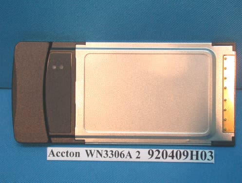
Click to zoom
Application Details
- Equipment Class
- DTS - Digital Transmission System
- Date of Grant
- Apr 27, 2003
- Application Purpose
- Original Equipment
- Date of Application
- Apr 27, 2003
- Equipment Note
- PCMCIA Wireless Card
- Frequency Range
- 2412.00000000 - 2462.00000000
- Company
- Accton Technology Corp
- Country
- Taiwan
Documents & Files
Document Text
Text extracted from the exhibit documents filed with the FCC. Open a document above to read the original.
Users Manual
IEEE802.11b Wireless LAN Card Quick Installation Guide WN3306A 2 wn3306-ZZ.book Page i Friday, April 18, 2003 3:55 PM wn3306-ZZ.book Page ii Friday, April 18, 2003 3:55 PM Quick Installation Guide IEEE802.11b Wireless LAN Card 11 Mbps Wireless LAN Card wn3306-ZZ.book Page iii Friday, April 18, 2003 3:55 PM WN3306A 2 E042003-R01 150200017600E wn3306-ZZ.book Page iv Friday, April 18, 2003 3:55 PM i Contents Introduction 1 Features 1 Applications 2 System Requirements 2 Package Checklist 2 Hardware Description 3 LED Indicator 3 Hardware Installation 4 Driver and Utility Installation 5 Windows 98/Me/2000 Installation 5 Windows XP Installation 7 Utility Configuration 10 Using Monitor Utility 10 Status 10 Configuration 11 Encryption 12 About 13 Using the Windows XP Configuration Tool 14 Basic Settings 14 Advanced Settings 16 Network Configuration and Planning 17 Network Topologies 17 Ad Hoc Wireless LAN 17 Infrastructure Wireless LAN 18 Setting the Communication Domain 19 Stationary Wireless PCs 19 Roaming Wireless PCs 19 Troubleshooting 20 Adapter Installation Problems 20 Network Connection Problems 21 Compliances 22 Federal Communication Commission Interference Statement 22 CSA Statement (Canada) 22 VCCI Class B Compliance (Japan) 23 CE Mark Declaration of Conformance for EMI and Safety (EEC) 23 wn3306-ZZ.book Page i Friday, April 18, 2003 3:55 PM Contents ii Specifications 24 General Specifications 24 Software Drivers 25 wn3306-ZZ.book Page ii Friday, April 18, 2003 3:55 PM 1 Introduction The Wireless LAN Card is an 11 Mbps wireless network adapter that seamlessly integrates with existing Ethernet networks to support applications such as mobile users or temporary conferences. This solution offers a high data rate and reliable wireless connectivity with considerable cost savings over wired LANs (which include long-term maintenance overhead for cabling). Just install enough wireless access points to cover your network area, plug wireless cards into your notebooks, and start networking. Using this card in conjunction with a wireless access point, you can create an instant network that integrates seamlessly with the existing 10/100 Mbps Ethernet LANs. Moreover, moving or expanding your network is as easy as moving or installing additional access points – no wires! Features •1, 2, 5.5 and 11 Mbps data rate. •Wireless connection without the hassles and cost of cabling •Greater flexibility to locate or move networked PCs •Integrates with or replaces wired LANs at dramatically lower cost than wired alternatives •Seamless connectivity to wired Ethernet LANs augments existing networks quickly and easily •Easy installation •Working range up to 30 m (100 ft) at 11 Mbps, up to 100 m (300 ft) at 5.5 Mbps; or lower indoors •Direct Sequence Spread-Spectrum (DSSS) technology provides robust, interference-resistant and secure wireless connection •Supports a wide range of systems (Windows 98/Me/2000/XP) •Provides a user-friendly interface for configuration •Enhances your network security with WEP data encryption and WPA •Built-in antenna •Support muitiple language in Card Configuration Manager Application Program •Support Domain Channel Selection (DCS) for users traveling to different countries wn3306-ZZ.book Page 1 Friday, April 18, 2003 3:55 PM Wireless PC Card 2 Applications Offers a fast, reliable, cost-effective solution for wireless client access to the network in applications like these: •Remote access to corporate network information E-mail, file transfer, and terminal emulation •Difficult-to-wire environments Historic or old buildings, asbestos installations, and open areas where wiring is difficult to employ •Frequently changing environments Retailers, manufacturers, and banks who frequently rearrange the workplace and change location •Temporary LANs for special projects or peak times Trade shows, exhibitions, and construction sites that need a temporary setup for a short time period. Retailers, airline, and shipping companies that need additional workstations for peak periods. Auditors who require workgroups at customer sites •Access to databases for mobile workers Doctors, nurses, retailers, office workers who need access to databases while being mobile in the hospital, retail store or office campus •SOHO (Small Office and Home Office) users SOHO users who need easy and quick installation of a small computer network System Requirements Before you install the Wireless LAN Card, check your system for the following: •A laptop with a PCMCIA Type II slot •Windows 98/Me/2000/XP (Prepare the Windows installation CD-ROM for use during installation) •A minimum of 1500 Kbytes of free disk space for installing the driver and utility program •Other IEEE 802.11b-compliant devices installed in your network area Package Checklist The Wireless LAN Card package includes: •1 Wireless LAN Card •1 Installation CD with Driver/Utility/User manual •This Quick Installation Guide Please inform your dealer if there are any incorrect, missing, or damaged parts. If possible, retain the carton, including the original packing materials, if there is a need to return the product for repair. wn3306-ZZ.book Page 2 Friday, April 18, 2003 3:55 PM Hardware Description 3 Hardware Description The Wireless LAN Card supports 1, 2, 5.5 and 11 Mbps connections to Ethernet networks. This card is fully compliant with 2.4 GHz DSSS CSMA/CA wireless networking as defined in IEEE 802.11b. It can be installed in any notebook with a Type II PCMCIA slot. It supports Windows 98/Me/2000/XP. LED Indicator The following figure and table deccribe the status LED indicator of the Wireless LAN Card. LEDStatusDescription Link/ActOnIndicates a valid connection with an access point. FlashingIndicates that data is been transmitted Link/Act wn3306-ZZ.book Page 3 Friday, April 18, 2003 3:55 PM Wireless PC Card 4 Hardware Installation Warnings: •Network cards are sensitive to static electricity. To protect the card, always touch the metal chassis of your computer…
Text truncated - open the document above for the full version.
External Photos
Page 1 CONSTRUCTION PHOTOS OF EUT Page 2
ID Label/Location Info
UL Label White mylor+PP UL Label R01 + 0.2 MM Scale:1:1 50# Black100% 92 04 15 WA3306A 2 146000029800E Sylin R3mm*4 Complies with Canada RSS-210 5 8 . 0 0 41.00 Vendor ID (Arial Narrow, Point 5) MFG Factory (Label Here) MFG Country (Arial Narrow, Point 5) Serial number 38*6mm WN3306A 2
ID Label/Location Info
(Fig. 1) FCC ID: HEDWN3306A2ACC FCC LABEL LOCATION The label will be permanently affixed at a conspicuous location on the device. Label
Internal Photos
Page 1 CONSTRUCTION PHOTOS OF EUT Page 2 Page 3
Operational Description
FCC ID: HEDWN3306A2ACC ADT No.920409H03 Operational Description The transmitter of the EUT is powered by host equipment. The antenna is Printed Antenna. There is no antenna connector. The other instruction, please have a look at the users manual. DSSS Information This device is Direct Sequence Spread Spectrum, the data is mixed by pseudorandom code which is an orthogonal code. The mixed data is digital modulated by BPSK and QPSK technique depends on the data rates. The CCK coding is applied for increasing the data rate, and also the processing gain will be increased. The bit rates are 1,2,5.5,11Mbps, the symbol rates are 1,1,1.375,1.375Mbps, the chip rates are always 11Mbps. So, the Chip/symbol is 11,11,8 and 8 respectively. Although is higher bit rate, the processing gain is lower than 10, but the CCK coding used in higher bit rate will provide 2.2dB coding gain.
RF Exposure Info
FCC ID: HEDWN3306A2ACC Report No.: SA920409H03 1 Issued: April 18, 2003 SAR TEST REPORT REPORT NO.: SA920409H03 MODEL NO.: WN3306A 2 RECEIVED: April 17, 2003 TESTED: April 17, 2003 APPLICANT: Accton Technology Corporation ADDRESS:No.1, Creation Rd. III, Science-based Industrial Park, Hsinchu, Taiwan, ROC ISSUED BY:Advance Data Technology Corporation LAB LOCATION:47 14th Lin, Chiapau Tsun, Linko, Taipei, Taiwan, R.O.C. This test report consists of 15 pages in total except Appendix. It may be duplicated completely for legal use with the approval of the applicant. It should not be reproduced except in full, without the written approval of our laboratory. The client should not use it to claim product endorsement by CNLA, NVLAP or any government agencies. The test results in the report only apply to the tested sample. FCC ID: HEDWN3306A2ACC Report No.: SA920409H03 2 Issued: April 18, 2003 Table of Contents 1.CERTIFICATION .................................................................................................................3 2.GENERAL INFORMATION ................................................................................................. 4 2.1GENERAL DESCRIPTION OF EUT ................................................................................... 4 2.2GENERAL DESCRIPTION OF APPLIED STANDARDS .................................................... 4 2.3GENERAL INOFRMATION OF THE SAR SYSTEM .......................................................... 5 2.4GENERAL DESCRIPTION OF THE PROBE SCAN RULE................................................ 7 3.DESCRIPTION OF TEST MODES AND CONFIGURATIONS ........................................... 8 4.DESCRIPTION OF SUPPORT UNITS ............................................................................... 9 5.TEST RESULTS................................................................................................................ 10 5.1TEST PROCEDURES....................................................................................................... 10 5.2MEASURED SAR RESULT .............................................................................................. 10 5.3SAR LIMITS ...................................................................................................................... 11 5.4EUT CONDUCTED POWER VARIATION ........................................................................ 11 5.5TISSUE ............................................................................................................................. 12 5.6TEST EQUIPMENT FOR TISSUE PROPERTY ............................................................... 12 6.SYSTEM VALIDATION...................................................................................................... 13 7.MEASUREMENT UNCERTAINTIES ................................................................................ 14 8.INFORMATION ON THE TESTING LABORATORIES ..................................................... 15 APPENDIX A: TEST CONFIGURATIONS AND TEST DATA APPENDIX B: ADT SAR MEASUREMENT SYSTEM APPENDIX C: PHOTOGRAPHS OF SYSTEM VALIDATION APPENDIX D: SYSTEM CERTIFICATE & CALIBRATION FCC ID: HEDWN3306A2ACC Report No.: SA920409H03 3 Issued: April 18, 2003 1. CERTIFICATION PRODUCT : PCMCIA Wireless Card MODEL NO. : WN3306A 2 BRAND NAME : Accton APPLICANT : Accton Technology Corporation. STANDARDS : 47 CFR Part 2 (Section 2.1093), FCC OET Bulletin 65, Supplement C (01-01), RSS-102 We, Advance Data Technology Corporation, hereby certify that one sample of the designation has been tested in our facility on 17 th April. 2003. The test record, data evaluation and Equipment Under Test (EUT) configurations represented herein are true and accurate, and it was tested according to the standards listed above. This device was found to be in compliance with the Specific Absorption Rate (SAR) requirement specified in FCC part 2.1093 under General Population / Uncontrolled Exposure condition. FCC ID: HEDWN3306A2ACC Report No.: SA920409H03 4 Issued: April 18, 2003 2. GENERAL INFORMATION 2.1 GENERAL DESCRIPTION OF EUT PRODUCTPCMCIA Wireless LAN Card MODEL NO.WN3306A 2 POWER SUPPLY3.3VDC powered by host equipment CLASSIFICATIONPortable device, production unit MODULATION TYPE BPSK, QPSK, CCK RADIO TECHNOLOGY DSSS TRANSFER RATE 1~11Mbps FREQUENCY RANGE2412MHz ~ 2462MHz NUMBER OF CHANNEL11 CONDUCTED OUTPUT POWER 61.51mW ANTENNA TYPEInternal Antenna PEAK SAR0.0962W/kg DATA CABLENA I/O PORTSPCMCIA ASSOCIATED DEVICESNA 2.2 GENERAL DESCRIPTION OF APPLIED STANDARDS According to the specifications of the manufacturer, this product must comply with the requirements of the following standards: FCC 47 CFR Part 2 (2.1093) FCC OET Bulletin 65, Supplement C (01- 01) RSS-102 All tests have been performed and recorded as per the above standards. FCC ID: HEDWN3306A2ACC Report No.: SA920409H03 5 Issued: April 18, 2003 2.3 GENERAL INOFRMATION OF THE SAR SYSTEM DASY4 (software 4.1, build 33) consists of high precision robtics system, probe alignment sensor, phantom, robot controller, controlled PC and near-field probe. The robot includes six axis that can move to the precision position of the DASY4 software defined. The DASY4 software can define the area which is detected by the probe. The robot is connected to controlled box. Controlled PC is connected to the controlled robot box. The DAE includes amplifier, signal multiplexing, AD converter, offset measurement, surface detection. It is connected to the Electro-optical coupler (ECO). The ECO performs the conversion form the optical into digital electric signal of the DAE and transfers data to the PC. ET3DV6 ISOTROPIC E-FIELD PROBE Construction Symmetrical design with triangular core. Built-in optical fiber for surface detection system. Built-in shielding against static charges. PEEK enclosure material (resistant to organic solvents, e.g., glycolether). Calibration Basic Broad Band Calibration in air: 10-2500 MHz Conversion Factors (CF) for HSL 900 and HSL…
Text truncated - open the document above for the full version.
Test Report
FCC ID: HEDWN3306A2ACC Report No.: RF920409H031Issued: Apr. 1, 2003 ADT No. 920409H03 FCC TEST REPORT REPORT NO.: RF920409H03 MODEL NO.: WN3306A 2 RECEIVED: Apr. 09, 2003 TESTED: Apr. 09 to 15, 2003 APPLICANT: Accton Technology Corporation ADDRESS: No.1, Creation Rd. III, Science-based Industrial Park, Hsinchu, Taiwan, R.O.C ISSUED BY: Advance Data Technology Corporation LAB LOCATION: No. 81-1, Lu Liao Keng, 9 Ling, Wu Lung Tsuen, Chiung Lin Hsiang, Hsin Chu Hsien, Taiwan, R.O.C. This test report consists of 49 pages in total. It may be duplicated completely for legal use with the approval of the applicant. It should not be reproduced except in full, without the written approval of our laboratory. The client should not use it to claim product endorsement by CNLA, NVLAP or any government agencies. The test results in the report only apply to the tested sample. Lab Code: 200376-0 FCC ID: HEDWN3306A2ACC Report No.: RF920409H032Issued: Apr. 1, 2003 ADT No. 920409H03 Table of Contents 1CERTIFICATION......................................................................................................4 2SUMMARY OF TEST RESULTS...........................................................................5 3GENERAL INFORMATION....................................................................................6 3.1GENERAL DESCRIPTION OF EUT.....................................................................6 3.2DESCRIPTION OF TEST MODES.......................................................................7 3.3GENERAL DESCRIPTION OF APPLIED STANDARDS..................................7 3.4DESCRIPTION OF SUPPORT UNITS.................................................................8 4TEST TYPES AND RESULTS...............................................................................9 4.1CONDUCTED EMISSION MEASUREMENT......................................................9 4.1.1TEST INSTRUMENTS...............................................................................................9 4.1.2TEST PROCEDURES.............................................................................................10 4.1.3DEVIATION FROM TEST STANDARD...................................................................10 4.1.4TEST SETUP............................................................................................................11 4.1.5EUT OPERATING CONDITIONS............................................................................12 4.1.6TEST RESULTS.......................................................................................................13 4.2RADIATED EMISSION MEASUREMENT.........................................................19 4.2.1LIMITS OF RADIATED EMISSION MEASUREMENT............................................19 4.2.2TEST INSTRUMENTS.............................................................................................20 4.2.3TEST PROCEDURES.............................................................................................21 4.2.4DEVIATION FROM TEST STANDARD...................................................................21 4.2.5TEST SETUP...........................................................................................................22 4.2.6EUT OPERATING CONDITIONS............................................................................22 4.2.7TEST RESULTS.......................................................................................................23 4.36dB BANDWIDTH MEASUREMENT.................................................................27 4.3.1LIMITS OF 6dB BANDWIDTH MEASUREMENT....................................................27 4.3.2TEST INSTRUMENTS.............................................................................................27 4.3.3TEST PROCEDURE................................................................................................28 4.3.4DEVIATION FROM TEST STANDARD...................................................................28 4.3.5TEST SETUP...........................................................................................................28 4.3.6EUT OPERATING CONDITIONS............................................................................28 4.3.7TEST RESULTS.......................................................................................................29 4.4MAXIMUM PEAK OUTPUT POWER.................................................................33 4.4.1LIMITS OF MAXIMUM PEAK OUTPUT POWER MEASUREMENT......................33 4.4.2INSTRUMENTS........................................................................................................33 4.4.3TEST PROCEDURES.............................................................................................34 4.4.4DEVIATION FROM TEST STANDARD...................................................................34 4.4.5TEST SETUP...........................................................................................................34 FCC ID: HEDWN3306A2ACC Report No.: RF920409H033Issued: Apr. 1, 2003 ADT No. 920409H03 4.4.6EUT OPERATING CONDITIONS............................................................................34 4.4.7TEST RESULTS.......................................................................................................35 4.4.8LIMITS OF POWER SPECTRAL DENSITY MEASUREMENT...............................36 4.4.9TEST INSTRUMENTS.............................................................................................36 4.4.10TEST PROCEDURE................................................................................................37 4.4.11DEVIATION FROM TEST STANDARD...................................................................37 4.4.12TEST SETUP...........................................................................................................37 4.4.13EUT OPERATING CONDITION...............................................................................37 4.4.14TEST RESULTS....................…
Text truncated - open the document above for the full version.
Test Report
Report No.920409H03 ADT No.920409H03 1 The Measurement of Conducted Spurious Emissions CONDUCTED SPURIOUS EMISSIONS MEASUREMENT 1. LIMITS OF CONDUCTED SPURIOUS EMISSIONS EASUREMENT Below 20dB of the highest emission level of operating band (in 100KHz Resolution Bandwidth, see Section 15.247(c)). Emissions which fall in the restricted bands, as defined in Section 15.205(a), must also comply with the limits specified in Section 15.209(a) (see Section 15.205(c)). 2. TEST INSTRUMENTS Description & Manufacturer Model No. Serial No. Calibrated Until R&S SPECTRUM ANALYZER FSP 1093.4495.30 Dec. 19, 2003 NOTE: 1.The measurement uncertainty is less than +/- 2.6dB, which is calculated as per the NAMAS document NIS81. 2.The calibration interval of the above test instruments is 12 months and the calibrations are traceable to NML/ROC and NIST/USA. 3. TEST PROCEDURE The transmitter output was connected to the spectrum analyzer via a low lose cable. Set both RBW and VBW of spectrum analyzer to 100 kHz with suitable frequency span including 100 kHz bandwidth from band edge. The band edges was measured and recorded. Report No.920409H03 ADT No.920409H03 2 4. TEST SETUP 5. EUT OPERATING CONDITIONS The software provided by client to enable the EUT under transmission condition continuously at lowest, middle and highest channel frequencies individually. EUT SPECTRUM ANALYZER Report No.920409H03 ADT No.920409H03 3 TEST RESULTS The spectrum plots are attached on the following 2 pages. It shows compliance with the requirement in part 15.247(C),.15.205 and 15.209. Report No.920409H03 ADT No.920409H03 4 Ch1 Report No.920409H03 ADT No.920409H03 5 Ch1 Report No.920409H03 ADT No.920409H03 6 Ch11 Report No.920409H03 ADT No.920409H03 7 Ch11
Test Setup Photos
FCC ID: HEDWN3306A2ACC Report No.: RF920409H03 47 Issued: Apr. 1, 2003 ADT No. 920409H03 5 PHOTOGRAPHS OF THE TEST CONFIGURATION CONDUCTED EMISSION TEST FCC ID: HEDWN3306A2ACC Report No.: RF920409H03 48 Issued: Apr. 1, 2003 ADT No. 920409H03 RADIATED EMISSION TEST
Contact Information
Applicant
Abby Wei(Manager)
Technical Contact
Advance Data Technology CorporationEric Lin
[email protected]+886 3 593 5343
81-1 Luliaoken, 9 th Lin, Wulung Tsuen Chiunglin · Hsinchu · Taiwan
Test Firm
Bureau Veritas CPS (H.K.) Ltd. Taoyuan BranchRichard Chen
Technical Specifications
| # | Rule Parts | Frequency Range | Power Output |
|---|---|---|---|
| 1 | 15C | 2.41 GHz - 2.46 GHz | 61.52 mW |
Other Applications from Accton Technology Corp

HEDEAP115
Jan 27, 2026Wi-Fi 7 AP
Equipment Class
NII - Unlicensed National Information Infrastructure TX
HEDEAP112
Oct 13, 2024Wi-Fi 6 IoT Gateway
Equipment Class
DTS - Digital Transmission System
HEDEAP111
Mar 17, 2024Wi-Fi 6 Access Point
Equipment Class
DTS - Digital Transmission System
HEDOAP101E
Oct 24, 2023Outdoor Access Point
Equipment Class
DTS - Digital Transmission System
HEDEAP104
Dec 14, 2022Indoor Wall Plate WiFi 6 Access Point
Equipment Class
DTS - Digital Transmission System