HEDWN4201BARC11g Wireless PCI Adapter
Accton Technology Corp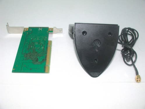
Click to zoom
Application Details
- Equipment Class
- DTS - Digital Transmission System
- Date of Grant
- Sep 29, 2003
- Application Purpose
- Original Equipment
- Date of Application
- Sep 29, 2003
- Equipment Note
- 11g Wireless PCI Adapter
- Frequency Range
- 2412.00000000 - 2462.00000000
- Company
- Accton Technology Corp
- Country
- Taiwan
Documents & Files
Document Text
Text extracted from the exhibit documents filed with the FCC. Open a document above to read the original.
Users Manual
11g Wireless PCI Adapter User’s Manual HP.book Page i Thursday, August 21, 2003 1:16 PM HP.book Page ii Thursday, August 21, 2003 1:16 PM User’s Manual 11g Wireless PCI Adapter HP.book Page iii Thursday, August 21, 2003 1:16 PM WN4201B-18 E082003-R01 HP.book Page iv Thursday, August 21, 2003 1:16 PM i Contents Introduction 1 Features 1 Applications 1 Package Checklist 1 Hardware Description 2 LED Indicators 2 Antenna 3 How to Install and position the remote antenna 3 Using Windows XP Wireless Zero Configuration 5 Network Configuration and Planning 16 Network Topologies 16 Ad Hoc Wireless LAN 16 Infrastructure Wireless LAN 17 Troubleshooting 18 Customer Support 19 Compliances 20 Federal Communication Commission Interference Statement 20 CSA Statement (Canada) 20 CE Mark Declaration of Conformance for EMI and Safety (EEC) 21 Specifications 22 HP.book Page i Thursday, August 21, 2003 1:16 PM Contents ii HP.book Page ii Thursday, August 21, 2003 1:16 PM 1 Introduction The 11g Wireless PCI adapter is a 54 Mbps wireless network adapter that seamlessly integrates with existing Ethernet networks to support multiple applications. This solution offers a high data rate and reliable wireless connectivity with considerable cost savings over wired LANs (which include long-term maintenance overhead for cabling). Just install the access point or wireless router and configure your wireless adapter in your PC, and your home is connected. Features •Up to 54 Mbps data rate •Wireless connection without hassles and cost of cabling •Greater flexibility to locate or move networked PCs •Seamless connectivity to wired Ethernet LANs augments existing networks quickly and easily •Device and the driver are pre-installed in your system •Auto fallback data rate under noisy environment •Orthogonal Frequency Division Multiplexing (OFDM) technology provides robust, wireless connection •Enhances your network security with WEP and WPA encryption Applications The 11g Wireless PCI adapter offers a fast, reliable, cost-effective solution for wireless client access to the network in applications such as: •Remote access to corporate network information Email, file transfer, and terminal emulation •Difficult-to-wire environments Historic or old buildings, asbestos installations, and open areas where wiring is difficult to employ •SOHO users SOHO (Small Office Home Office) users who need easy and quick installation of a small computer network Package Checklist The 11g Wireless PCI Adapter package includes: •One external antenna with attached cable and wall mounting kit •One Quick Installation Guide HP.book Page 1 Thursday, August 21, 2003 1:16 PM 2 Hardware Description The 11g Wireless PCI Adapter supports up to 54 Mbps connections to Ethernet networks. This adapter is fully compliant with the IEEE 802.11g specifications and certified by Wi-Fi. LED Indicators There are two status LED indicators on the adapter, as described in the following figure and table. LEDStatusDescription Power/LinkOnIndicates a valid connection. FlashingIndicates that the adapter is scanning for available networks. ActivityFlashingIndicates that the adapter is transmitting or receiving packets. Activity Antenna Connector Power/Link HP.book Page 2 Thursday, August 21, 2003 1:16 PM 3 Antenna The 11g Wireless PCI Adapter comes with one external antenna. How to Install and position the remote antenna •Screw the antenna to the antenna connector located on the back of your desktop PC •Place the antenna on the desktop PC, table, or mount it on the wall, to get better data transmission and reception • Keep the antenna patch facing toward your Access Point (AP) or Wireless Broadband Router Adjustable Panel Antenna Connector Front view of the remote antenna Antenna Connector Antenna Connector on the adapter HP.book Page 3 Thursday, August 21, 2003 1:16 PM 4 Note: A clear and open area provides better wireless performance. Performance may be affected by the interference of microwave ovens and 2.4GHz cordless phones. Access Point or Wireless Broadband Router HP.book Page 4 Thursday, August 21, 2003 1:16 PM Using Windows XP Wireless Zero Configuration 5 Using Windows XP Wireless Zero Configuration It is recommended that you use Windows XP’s built-in program, Wireless Zero Configuration, to manage the 11g Wireless PCI adapter. For details on how to use Microsoft Windows Zero Configuration tool to set up a wireless network, go to the following web site at http://www.microsoft.com/technet/treeview/default.asp?url=/technet/columns/cableguy/cg 1102.asp. You can choose either Option A or Option B to open the program, follow these steps: Step 1 Option A: •Go to your system tray (located on the lower right hand corner of your screen), and right-click on the Wireless Network Connection icon. Select “View Available Wireless Networks”. •The Wireless Network Connection window will then appear. If your network is shown on the list, select it and enter the Network key, confirm the key again, and click Connect. For detailed settings, click Advanced (proceed to step 2 on the following page for configuration). HP.book Page 5 Thursday, August 21, 2003 1:16 PM 6 Step 1 Option B: •Go to Start menu, Control Panel, and open Network Connections. Right-click on Wireless Network Connection, and select Properties. Step 2 Go to the Wireless Networks tab, you can view and configure these settings here: •Use Windows to configure my wireless network settings — This box is checked by default. •Available networks — The available networks within the adapter’s signal range. To set the configuration of a specific wireless network and add it to the list of preferred networks, select it from the list, and then click Configure. Click Refresh to scan for available wireless networks within range. •Preferred networks — This is a list of preferred networks. You can organize several networks for your adapter to connect in different locations. If you want to add a new wireless network that does not appear in the…
Text truncated - open the document above for the full version.
External Photos
Page 1 CONSTRUCTION PHOTOS OF EUT Page 2
ID Label/Location Info
(Fig. 1) FCC ID: HEDWN4201BARC LABEL LOCATION Label
ID Label/Location Info
27.58 35.48 28.52 17.87 25.90 6.62 2.97 2.97 7 . 6 8 5.0
Internal Photos
Page 1 CONSTRUCTION PHOTOS OF EUT Page 2 Page 3 Page 4
Operational Description
FCC ID: HEDWN4201BARC ADT No. 920827H02 Operational Description This device is a 11g Wireless PCI Adapter in the 2.4GHz band, the maximum data rate could be up to 54Mbps which OFDM technique will be applied. If the signal to noise radio is too poor which could not support 54Mbps, the 11Mbps data rate with CCK technique will be applied. The transmitter of the EUT (11g Wireless PCI Adapter) is powered by from host equipment. The antenna type used in this product is External Directional Antenna with RP -SMA plug connector The other instruction, please have a look at the users manual.
Test Report
FCC ID: HEDWN4201BARC Report No.: RF920827H021Issed: Sep.22, 2003 ADT No.: 920827H02 FCC TEST REPORT REPORT NO.: RF920827H02 MODEL NO.: WN4201B RECEIVED: Aug. 27, 2003 TESTED: Sep. 04 to 17, 2003 APPLICANT: Accton Technology Corporation ADDRESS: No.1, Creation Rd. III, Science-based Industrial Park, Hsinchu, Taiwan, R.O.C. ISSUED BY: Advance Data Technology Corporation LAB LOCATION: No. 81-1, Lu Liao Keng, 9 Ling, Wu Lung Tsuen, Chiung Lin Hsiang, Hsin Chu Hsien, Taiwan, R.O.C. This test report consists of 72 pages in total. It may be duplicated completely for legal use with the approval of the applicant. It should not be reproduced except in full, without the written approval of our laboratory. The client should not use it to claim product endorsement by CNLA, NVLAP or any government agencies. The test results in the report only apply to the tested sample. Lab Code: 200376-0 FCC ID: HEDWN4201BARC Report No.: RF920827H022Issed: Sep.22, 2003 ADT No.: 920827H02 Table of Contents 1CERTIFICATION.......................................................................................................4 2SUMMARY OF TEST RESULTS...........................................................................5 3GENERAL INFORMATION.....................................................................................6 3.1GENERAL DESCRIPTION OF EUT......................................................................6 3.2DESCRIPTION OF TEST MODES........................................................................7 3.3GENERAL DESCRIPTION OF APPLIED STANDARDS...................................7 3.4DESCRIPTION OF SUPPORT UNITS.................................................................8 4TEST TYPES AND RESULTS..............................................................................11 4.1CONDUCTED EMISSION MEASUREMENT....................................................11 4.1.1LIMITS OF CONDUCTED EMISSION MEASUREMENT................................11 4.1.2TEST INSTRUMENTS...........................................................................................11 4.1.3TEST SETUP..........................................................................................................12 4.1.4EUT OPERATING CONDITIONS........................................................................13 4.1.5TEST RESULTS (A)...............................................................................................14 4.1.6TEST RESULTS (B)...............................................................................................16 4.2RADIATED EMISSION MEASUREMENT..........................................................18 4.2.1LIMITS OF RADIATED EMISSION MEASUREMENT.....................................18 4.2.2TEST INSTRUMENTS...........................................................................................19 4.2.3TEST PROCEDURES...........................................................................................20 4.2.4TEST SETUP..........................................................................................................21 4.2.5EUT OPERATING CONDITIONS........................................................................21 4.2.6TEST RESULTS (A)...............................................................................................22 4.2.7TEST RESULTS (A) - DSSS................................................................................23 4.2.8TEST RESULTS (A) -OFDM.................................................................................26 4.2.9TEST RESULTS (B)...............................................................................................29 4.2.10TEST RESULTS (B) - DSSS................................................................................31 4.2.11TEST RESULTS (B) -OFDM.................................................................................34 4.36dB BANDWIDTH MEASUREMENT..................................................................37 4.3.1LIMITS OF 6dB BANDWIDTH MEASUREMENT.............................................37 4.3.2TEST INSTRUMENTS...........................................................................................37 4.3.3TEST PROCEDURE..............................................................................................38 4.3.4TEST SETUP..........................................................................................................38 4.3.5EUT OPERATING CONDITIONS........................................................................38 4.3.6TEST RESULTS-DSSS.........................................................................................39 4.3.7TEST RESULTS-OFDM........................................................................................43 FCC ID: HEDWN4201BARC Report No.: RF920827H023Issed: Sep.22, 2003 ADT No.: 920827H02 4.4MAXIMUM PEAK OUTPUT POWER..................................................................47 4.4.1LIMITS OF MAXIMUM PEAK OUTPUT POWER MEASUREMENT.............47 4.4.2TEST INSTRUMENTS...........................................................................................47 4.4.3TEST PROCEDURES...........................................................................................48 4.4.4TEST SETUP..........................................................................................................48 4.4.5EUT OPERATING CONDITIONS........................................................................48 4.4.6TEST RESULTS-DSSS.........................................................................................49 4.4.7TEST RESULTS-OFDM........................................................................................49 4.5POWER SPECTRAL DENSITY MEASUREMENT...........................................50 4.5.1LIMITS OF POWER SPECTRAL DENSITY MEASUREMENT......................50 4.5.2TEST INSTRUMENTS...........................................................................................50 4.5.3TEST PROCEDURE.................................…
Text truncated - open the document above for the full version.
Test Report
Report No. 920827H02 1 The Measurement of Conducted Spurious Emissions CONDUCTED SPURIOUS EMISSIONS MEASUREMENT 1. LIMITS OF CONDUCTED SPURIOUS EMISSIONS EASUREMENT Below 20dB of the highest emission level of operating band (in 100KHz Resolution Bandwidth, see Section 15.247(c)). Emissions which fall in the restricted bands, as defined in Section 15.205(a), must also comply with the limits specified in Section 15.209(a) (see Section 15.205(c)). 2. TEST INSTRUMENTS Description & ManufacturerModel No.Serial No.Calibrated Until R&S SPECTRUM ANALYZERFSP1093.4495.30Dec. 19, 2003 NOTE: 1.The measurement uncertainty is less than +/- 2.6dB, which is calculated as per the NAMAS document NIS81. 2.The calibration interval of the above test instruments is 12 months and the calibrations are traceable to NML/ROC and NIST/USA. 3. TEST PROCEDURE The transmitter output was connected to the spectrum analyzer via a low lose cable. Set both RBW and VBW of spectrum analyzer to 100 kHz with suitable frequency span including 100 kHz bandwidth from band edge. The band edges was measured and recorded. Report No. 920827H02 2 4. TEST SETUP 5. EUT OPERATING CONDITIONS The software provided by client to enable the EUT under transmission condition continuously at lowest, middle and highest channel frequencies individually. EUT SPECTRUM ANALYZER Report No. 920827H02 3 TEST RESULTS – For 802.11b The spectrum plots are attached on the following 2 pages. It shows compliance with the requirement in part 15.247(C),.15.205 and 15.209. Report No. 920827H02 4 Ch1 Report No. 920827H02 5 Ch11 Report No. 920827H02 6 TEST RESULTS – For 802.11g The spectrum plots are attached on the following 2 pages. It shows compliance with the requirement in part 15.247(C),.15.205 and 15.209. Report No. 920827H02 7 Ch1 Report No. 920827H02 8 Ch11
Test Setup Photos
FCC ID: HEDWN4201BARC Report No.: RF920827H0268Issed: Sep.22, 2003 ADT No.: 920827H02 5 PHOTOGRAPHS OF THE TEST CONFIGURATION CONDUCTED EMISSION TEST (For Compaq PC) FCC ID: HEDWN4201BARC Report No.: RF920827H0269Issed: Sep.22, 2003 ADT No.: 920827H02 CONDUCTED EMISSION TEST (For HP PC) FCC ID: HEDWN4201BARC Report No.: RF920827H0270Issed: Sep.22, 2003 ADT No.: 920827H02 RADIATED EMISSION TEST (For Compaq PC) FCC ID: HEDWN4201BARC Report No.: RF920827H0271Issed: Sep.22, 2003 ADT No.: 920827H02 RADIATED EMISSION TEST (For HP PC)
Contact Information
Applicant
Abby Wei(Manager)
Technical Contact
Advance Data Technology CorporationEric Lin
[email protected]+886 3593 5343
81-1 Luliaoken, 9th Lin, Wulung Tsuen Chiunglin · Hsinchu · Taiwan
Test Firm
Bureau Veritas CPS (H.K.) Ltd. Taoyuan BranchRichard Chen
Technical Specifications
| # | Rule Parts | Frequency Range | Power Output |
|---|---|---|---|
| 1 | 15C | 2.41 GHz - 2.46 GHz | 65.50 mW |
Other Applications from Accton Technology Corp

HEDEAP115
Jan 27, 2026Wi-Fi 7 AP
Equipment Class
NII - Unlicensed National Information Infrastructure TX
HEDEAP112
Oct 13, 2024Wi-Fi 6 IoT Gateway
Equipment Class
DTS - Digital Transmission System
HEDEAP111
Mar 17, 2024Wi-Fi 6 Access Point
Equipment Class
DTS - Digital Transmission System
HEDOAP101E
Oct 24, 2023Outdoor Access Point
Equipment Class
DTS - Digital Transmission System
HEDEAP104
Dec 14, 2022Indoor Wall Plate WiFi 6 Access Point
Equipment Class
DTS - Digital Transmission System