HEDWN6301ACCWLAN Mobile Adapter 2201
Accton Technology Corp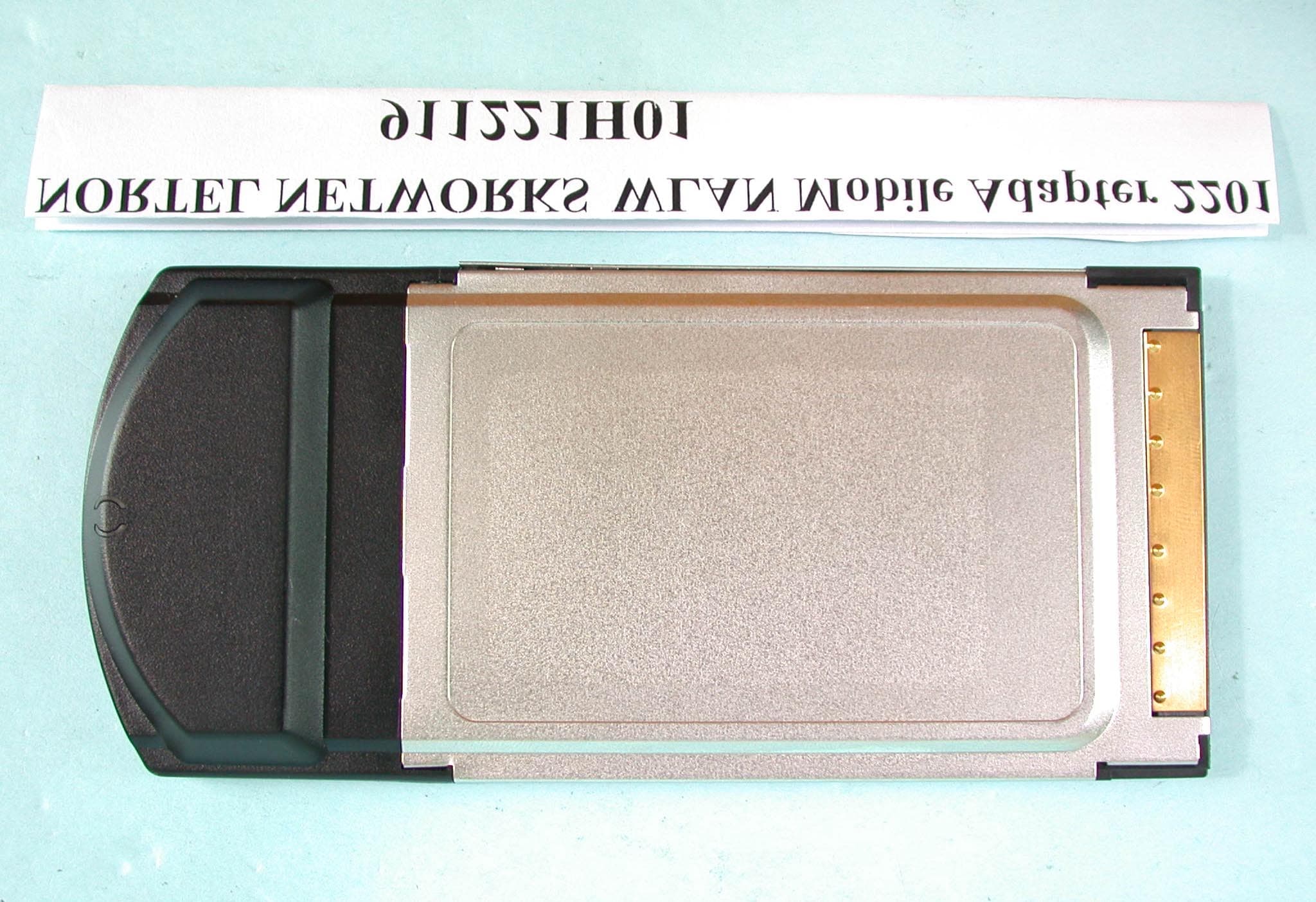
Click to zoom
Application Details
- Equipment Class
- NII - Unlicensed National Information Infrastructure TX
- Date of Grant
- May 29, 2003
- Application Purpose
- Original Equipment
- Date of Application
- Mar 24, 2003
- Equipment Note
- WLAN Mobile Adapter 2201
- Frequency Range
- 5725.00000000 - 5825.00000000
- Company
- Accton Technology Corp
- Country
- Taiwan
Documents & Files
Document Text
Text extracted from the exhibit documents filed with the FCC. Open a document above to read the original.
Users Manual
[Final Draft—Nortel Confidential] Part No. 214695-A April 2003 4655 Great America Parkway Santa Clara, CA 95054 Installing and Using the Nortel Networks Wireless LAN Mobile Adapter 2201 2 214695-A [Final Draft—Nortel Confidential] Copyright Statement No part of this publication may be reproduced, stored in a retrieval system, or transmitted in any form or by any means, whether electronic, mechanical, photocopying, recording or otherwise without the prior writing of the publisher. Windows 98SE/2000/ME/XP are trademarks of Microsoft Corp. Pentium is trademark of Intel. Nortel Networks and the Nortel Networks logo are trademarks of Nortel Networks, Inc. All copyright reserved. Compliances Federal Communication Commission Interference Statement This equipment has been tested and found to comply with the limits for a Class B digital device, pursuant to Part 15 of the FCC Rules. These limits are designed to provide reasonable protection against harmful interference in a residential installation. This equipment generates, uses and can radiate radio frequency energy and, if not installed and used in accordance with instructions, may cause harmful and, if not installed and used in accordance with instructions, may cause harmful interference to radio communications. However, there is no guarantee that the interference will not occur in a particular installation. If this equipment does cause harmful interference to radio or television reception, which can be determined by turning the equipment off and on, the user is encouraged to try to correct the interference by one or more of the following measures: •Reorient the receiving antenna •Increase the separation between the equipment and receiver •Connect the equipment into an outlet on a circuit different from that to which the receiver is connected •Consult the dealer or an experienced radio/TV technician for help FCC Caution: To assure continued compliance, (example - use only shielded interface cables when connecting to computer or peripheral devices). Any changes or modifications not expressly approved by the party responsible for compliance could void the user’s authority to operate this equipment. This device complies with Part 15 of the FCC Rules. Operation is subject to the following two conditions: (1) This device may not cause harmful interference, and (2) this device must accept any interference received, including interference that may cause undesired operation. IMPORTANT NOTE: FCC Radiation Exposure Statement This equipment complies with FCC radiation exposure limits set forth for an uncontrolled environment. This transmitter must not be co-located or operating in conjunction with any other antenna or transmitter. This device is going to be operated in 5.15 ~ 5.25GHx frequency range, it is restricted in indoor environment only. In order to maintain compliance with the limits for a Class B digital device, it requires that you use a quality interface cable when connecting to this device. Changes or modifications not expressly approved could void the user’s authority to operate this equipment. 3 Installing and Using the Nortel Networks Wireless LAN Mobile Adapter 2201 [Final Draft—Nortel Confidential] Contents Preface . . . . . . . . . . . . . . . . . . . . . . . . . . . . . . . . . . . . . . . . . . . . . . . . . . . . . . . 9 Introduction . . . . . . . . . . . . . . . . . . . . . . . . . . . . . . . . . . . . . . . . . . . . . . . . . . . . . . . . . .9 Package Checklist . . . . . . . . . . . . . . . . . . . . . . . . . . . . . . . . . . . . . . . . . . . . . . . . . . 9 System Requirements . . . . . . . . . . . . . . . . . . . . . . . . . . . . . . . . . . . . . . . . . . . . . . . 9 Status LEDs . . . . . . . . . . . . . . . . . . . . . . . . . . . . . . . . . . . . . . . . . . . . . . . . . . . . . . 10 Chapter 1 Driver/Utility Installation . . . . . . . . . . . . . . . . . . . . . . . . . . . . . . . . . . . . . . . . 11 Basic Setup . . . . . . . . . . . . . . . . . . . . . . . . . . . . . . . . . . . . . . . . . . . . . . . . . . . . . . . . . 11 Additional Setup . . . . . . . . . . . . . . . . . . . . . . . . . . . . . . . . . . . . . . . . . . . . . . . . . . . . . . 18 Verifying the Driver . . . . . . . . . . . . . . . . . . . . . . . . . . . . . . . . . . . . . . . . . . . . . . . . . . . . 18 Windows 98SE/Me . . . . . . . . . . . . . . . . . . . . . . . . . . . . . . . . . . . . . . . . . . . . . . . . 18 Windows 2000 . . . . . . . . . . . . . . . . . . . . . . . . . . . . . . . . . . . . . . . . . . . . . . . . . . . . 19 Windows XP . . . . . . . . . . . . . . . . . . . . . . . . . . . . . . . . . . . . . . . . . . . . . . . . . . . . . 19 Uninstallation . . . . . . . . . . . . . . . . . . . . . . . . . . . . . . . . . . . . . . . . . . . . . . . . . . . . . . . .20 Chapter 2 Utility Configuration . . . . . . . . . . . . . . . . . . . . . . . . . . . . . . . . . . . . . . . . . . . 23 Connecting to an Existing Network . . . . . . . . . . . . . . . . . . . . . . . . . . . . . . . . . . . . . . . 23 Advanced settings for Windows XP . . . . . . . . . . . . . . . . . . . . . . . . . . . . . . . . . . . . . . . 28 Create a New Network Profile . . . . . . . . . . . . . . . . . . . . . . . . . . . . . . . . . . . . . . . . . . . 30 Chapter 3 Network Configuration . . . . . . . . . . . . . . . . . . . . . . . . . . . . . . . . . . . . . . . . . 35 Device Configuration . . . . . . . . . . . . . . . . . . . . . . . . . . . . . . . . . . . . . . . . . . . . . . . . . . 35 Infrastructure Mode . . . . . . . . . . . . . . . . . . . . . . . . . . . . . . . . . . . . . . . . . . . . . . . . 35 Ad Hoc Mode . . . . . . . . . . . . . . . . . . . . . . . . . . . . . . . . . . . . . . . . . . . . . . . . . . . . . 36 Non-Default Settings Configuration . . . . . . . . . . . . . . . . . . . . . . . . . . . . . . . . . . . . . . . 36 4Contents 214695-A [Final Draft—Nortel Confidential] Default Settings Windows XP Zero-Configuration . . . . . . . . . . …
Text truncated - open the document above for the full version.
Cover Letter(s)
[email protected] www.adt.com.tw ADVANCE DATA TECHNOLOGY CORPORATION FEDERAL COMMUNICATIONS COMMISSION DECLARATION OF CONFORMITY (DoC) FOR THE FOLLOWING EQUIPMENT: PRODUCT NAME : WLAN Mobile Adapter 2201 MODEL NO : WLAN Mobile Adapter 2201 TRADE NAME : NORTEL NETWORKS IS HEREWITH CONFIRMED AND FOUND TO COMPLY WITH THE REQUIREMENTS OF CFR 47 PART 15 REGULATION. THE RESULTS OF ELECTROMAGNETIC EMISSION EVALUATION ARE SHOWN IN THE REPORT NO : RF911221H01 THIS DEVICE COMPLIES WITH PART 15 OF THE FCC RULES. OPERATION IS SUBJECT TO THE FOLLOWING TWO CONDITIONS: (1) THIS DEVICE MAY NOT CAUSE HARMFUL INTERFERENCE AND, (2) THIS DEVICE MUST ACCEPT ANY INTERFERENCE RECEIVED, INCLUDING INTERFERENCE THAT MAY CAUSE UNDESIRED OPERATION. THE FOLLOWING LOCAL MANUFACTURER/IMPORTER IS RESPONSIBLE FOR THIS DECLARATION: ManufacturerUSA Local Representative Company name: Accton Technology Corporation To Be Determined. Address: No.1, Creation Rd. III, Science-based Industrial Park, Hsinchu, Taiwan, R.O.C. Contact Person: Hsoang-Shen Chen Title: Section Manager Te l / F a x : Tel:886-3-5770270 Fax:886-3-5783839
External Photos
Page 1 ANNEX PHOTOGRAPHS OF EUT Page 2
ID Label/Location Info
Tested To Comply With FCC Standards FOR HOME OR OFFICE USE 6 5 . 0 0 m m 41.00 mm FCC ID Label Location
Internal Photos
Page 3 Page 4 Page 5
RF Exposure Info
SAR COMPLIANCE TESTING OF ACCTON TECHNOLOGY CORPORATION WLAN MOBILE ADAPTER 2201 INSERTED INTO A COMPAQ LAPTOP COMPUTER MODEL: WLAN Mobile Adapter 2201 FCC ID: HEDWN 6301 ACC HOST COMPUTER: Compaq Evo N800C SERIAL #: PP2130 February 7, 2003 Prepared for: Accton Technology Corporation No. 1, Creation Road III Science-Based Industrial Park Hsinchu, Taiwan, R.O.C. Prepared by: Om P. Gandhi Professor of Electrical and Computer Engineering University of Utah 50 S Central Campus Dr., Rm. 3280 Salt Lake City, UT 84112-9206 ii TABLE OF CONTENTS I. Introduction ........................................................................................................................ 1 II. The SAR Measurement System ......................................................................................... 2 The Flat Phantom ............................................................................................................... 3 III. Calibration of the E-Field Probe ......................................................................................... 3 IV. SAR System Verification ................................................................................................... 4 V. Tissue Simulant Fluid for the Frequency Band 5.2 to 5.8 GHz ......................................... 5 VI. The Measured SAR Distributions....................................................................................... 6 VII. Comparison of the Data with FCC 96-326 Guidelines ...................................................... 8 REFERENCES ............................................................................................................................ 9 TABLES ................................................................................................................................ 11-21 FIGURES .............................................................................................................................. 22-46 APPENDIX A (separate pdf file) APPENDIX B ........................................................................................................................... 47 APPENDIX C ........................................................................................................................... 51 1 SAR COMPLIANCE TESTING OF ACCTON TECHNOLOGY CORPORATION WLAN MOBILE ADAPTER 2201 INSERTED INTO A COMPAQ LAPTOP COMPUTER MODEL: WLAN Mobile Adapter 2201 FCC ID: HEDWN 6301 ACC HOST COMPUTER: Compaq Evo N800C SERIAL #: PP2130 I. Introduction The U.S. Federal Communications Commission (FCC) has adopted limits of human exposure to RF emissions from mobile and portable devices that are regulated by the FCC [1]. The FCC has also issued Supplement C (Edition 97-01) to OET Bulletin 65 [2] and a more recent version of the same [3] defining both the measurement and the computational procedures that should be followed for evaluating compliance of mobile and portable devices with FCC limits for human exposure to radiofrequency emissions. We have used the measurement procedure for SAR compliance testing of the Accton Technology Corporation WLAN Mobile Adapter 2201, inserted into a Compaq Laptop Computer (Model Evo N800C, Serial #PP2130, manufactured by Compaq Computer Corporation, Korea). Photographs of the unit with the Mobile Adapter inserted into the laptop computer are given in Figs. 1a and 1b for top and bottom sides of the PC, respectively. A picture of the Mobile Adapter placed on the laptop is given in Fig. 2. The Accton Technology Corporation WLAN Mobile Adapter 2201 operates over the frequency band 5.18 to 5.825 GHz in normal or turbo modes with average conducted power levels as high as 21.8 dBm (151.4 mW). A characteristic of the Compaq host computer is that its keyboard is fairly thin. This results in a placement of the Mobile Adapter as close as 0.94 cm for the laptop placement of the PC. For SAR measurements, two configurations of the wireless PC relative to the experimental phantom have been used: a. Since the wireless PC may possibly be placed on a user's lap where the RF antennas would be the closest to the body, a planar phantom model with inside dimensions 2 12" x 16.5" (30.5 x 41.9 cm) and a base thickness of 2.0 ± 0.2 mm (recommended in [3]) was used for SAR measurements and the wireless PC adapter mounted in a portable computer (as in Fig. 1b) pressed against the bottom of this phantom (see Fig. 5). b. For a bystander, the "end-on" SAR value is obtained for the PC and the adapter edge at 90° to the flat phantom with a spacing of 2.5 cm (see Fig. 6). II. The SAR Measurement System The University of Utah SAR Measurement System has been described in peer-reviewed literature [Ref. 8 -- attached here as Appendix A]. A photograph of the SAR Measurement System is given in Fig. 3. This SAR Measurement System uses a computer-controlled 3-D stepper motor system (Arrick Robotics MD-2A). A triaxial Narda Model 8021 E-field probe is used to determine the internal electric fields. The positioning repeatability of the stepper motor system moving the E-field probe is within ±0.1 mm. Outputs from the three channels of the E- field probe are dc voltages, the sum of which is proportional to the square of the internal electric fields ( ) 2 i E from which the SAR can be obtained from the equation SAR = ( ) 2 i Eσρ, where σ and ρ are the conductivity and mass density of the tissue-simulant materials, respectively [5]. The dc voltages for the three channels of the E-field probe are read by three HP 34401A multimeters and sent to the computer via an HPIB interface. The setup is carefully grounded and shielded to reduce the noise due to the electromagnetic interference (EMI). A cutout in a wooden table of dimensions 38.1 × 21.6 cm allows placement of a plastic holder (shown in Fig. 4) on which the laptop computer with the Mobile Adapter (see Fig. 1) is supported. The plastic holder can be moved up or down so that the base of the Compaq PC is pressed against the base of the flat …
Text truncated - open the document above for the full version.
Test Report
FCC ID: HEDWN6301ACC Report No.: RF911221H01 1 Issued: Jan. 15, 2003 FCC TEST REPORT REPORT NO.: RF911221H01 MODEL NO.: WLAN Mobile Adapter 2201 RECEIVED: Dec. 25, 2002 TESTED: Jan. 4, 2003 ~ Jan. 7, 2003 APPLICANT: Accton Technology Corporation ADDRESS: No. 1, Creation Rd. III, Science-based Industrial Park, Hsinchu, Taiwan, R.O.C. ISSUED BY:Advance Data Technology Corporation LAB LOCATION:47 14 th Lin, Chiapau Tsun, Linko, Taipei, Taiwan, R.O.C. This test report consists of 141 pages in total. It may be duplicated completely for legal use with the approval of the applicant. It should not be reproduced except in full, without the written approval of our laboratory. The client should not use it to claim product endorsement by CNLA, NVLAP or any government agencies. The test results in the report only apply to the tested sample. 0528 ILAC MRA Lab Code: 200102-0 FCC ID: HEDWN6301ACC Report No.: RF911221H01 2 Issued: Jan. 15, 2003 Table of Contents 1.CERTIFICATION........................................................................................... 5 2.SUMMARY OF TEST RESULTS .................................................................. 6 3.GENERAL INFORMATION ........................................................................... 8 3.1GENERAL DESCRIPTION OF EUT ...................................................................................... 8 3.2DESCRIPTION OF TEST MODES ........................................................................................ 9 3.3GENERAL DESCRIPTION OF APPLIED STANDARDS ..................................................... 10 3.4DESCRIPTION OF SUPPORT UNITS................................................................................. 11 4.TEST TYPES AND RESULTS (FOR PART 802.11b) ................................. 12 4.1CONDUCTED EMISSION MEASUREMENT....................................................................... 12 4.1.1LIMITS OF CONDUCTED EMISSION MEASUREMENT .................................................... 12 4.1.2TEST INSTRUMENTS ......................................................................................................... 12 4.1.3TEST PROCEDURES .......................................................................................................... 13 4.1.4DEVIATION FROM TEST STANDARD ................................................................................ 13 4.1.5TEST SETUP ....................................................................................................................... 14 4.1.6EUT OPERATING CONDITIONS......................................................................................... 14 4.1.7TEST RESULTS ................................................................................................................... 15 4.2RADIATED EMISSION MEASUREMENT ............................................................................ 21 4.2.1LIMITS OF RADIATED EMISSION MEASUREMENT ......................................................... 21 4.2.2TEST INSTRUMENTS ......................................................................................................... 22 4.2.3TEST PROCEDURES .......................................................................................................... 23 4.2.4DEVIATION FROM TEST STANDARD ................................................................................ 23 4.2.5TEST SETUP ....................................................................................................................... 24 4.2.6EUT OPERATING CONDITIONS......................................................................................... 24 4.2.7TEST RESULTS ................................................................................................................... 25 4.36dB BANDWIDTH MEASUREMENT ................................................................................... 29 4.3.1LIMITS OF 6dB BANDWIDTH MEASUREMENT ................................................................ 29 4.3.2TEST INSTRUMENTS ......................................................................................................... 29 4.3.3TEST PROCEDURE ............................................................................................................30 4.3.4DEVIATION FROM TEST STANDARD ................................................................................ 30 4.3.5TEST SETUP ....................................................................................................................... 30 4.3.6EUT OPERATING CONDITIONS......................................................................................... 30 4.3.7TEST RESULTS ................................................................................................................... 31 4.4MAXIMUM PEAK OUTPUT POWER ................................................................................... 35 4.4.1LIMITS OF MAXIMUM PEAK OUTPUT POWER MEASUREMENT ................................... 35 4.4.2INSTRUMENTS.................................................................................................................... 35 4.4.3TEST PROCEDURES .......................................................................................................... 36 4.4.4DEVIATION FROM TEST STANDARD ................................................................................ 36 4.4.5TEST SETUP ....................................................................................................................... 36 4.4.6EUT OPERATING CONDITIONS......................................................................................... 36 4.4.7TEST RESULTS ................................................................................................................... 37 FCC ID: HEDWN6301ACC Report No.: RF911221H01 3 Issued: Jan. 15, 2003 4.5POWER SPECTRAL DENSITY MEASUREMENT .............................................................. 38 4.5.1LIMITS OF POWER SPECTRAL DENSITY MEASUREME…
Text truncated - open the document above for the full version.
Test Report
FCC ID: HEDWN6301ACC Report No.: RF911221H01 91 Issued: Jan. 15, 2003 CHANNEL 1 FCC ID: HEDWN6301ACC Report No.: RF911221H01 92 Issued: Jan. 15, 2003 CHANNEL 2 FCC ID: HEDWN6301ACC Report No.: RF911221H01 93 Issued: Jan. 15, 2003 CHANNEL 3 FCC ID: HEDWN6301ACC Report No.: RF911221H01 94 Issued: Jan. 15, 2003 CHANNEL 4 FCC ID: HEDWN6301ACC Report No.: RF911221H01 95 Issued: Jan. 15, 2003 CHANNEL 5 FCC ID: HEDWN6301ACC Report No.: RF911221H01 96 Issued: Jan. 15, 2003 5.4 PEAK POWER EXCURSION MEASUREMENT 5.4.1 LIMITS OF PEAK POWER EXCURSION MEASUREMENT Frequency BandLimit 5.15 – 5.25 GHz13dB 5.25 – 5.35 GHz13dB 5.725 – 5.825 GHz13dB 5.4.2 TEST INSTRUMENTS Description & ManufacturerModel No.Serial No.Calibrated Until SPECTRUM ANALYZERFSEK30100049July 24, 2003 NOTE: The calibration interval of the above test instruments is 12 months and the calibrations are traceable to NML/ROC and NIST/USA. FCC ID: HEDWN6301ACC Report No.: RF911221H01 97 Issued: Jan. 15, 2003 5.4.3 TEST PROCEDURE 1. The transmitter output was connected to the spectrum analyzer. 2. Set the spectrum bandwidth span to view the entire spectrum. 3. Using peak detector and Max-hold function for Trace 1 (RB=1MHz, VB=3MHz) and 2 (RB=1MHz, VB=300kHz). 4. The largest difference between Trace 1 and Trace 2 in any 1MHz band on any frequency was recorded. 5.4.4 DEVIATION FROM TEST STANDARD No deviation 5.4.5 TEST SETUP 5.4.6 EUT OPERATING CONDITIONS The software provided by client to enable the EUT under transmission condition continuously at specific channel frequencies individually. EUT SPECTRUM FCC ID: HEDWN6301ACC Report No.: RF911221H01 98 Issued: Jan. 15, 2003 5.4.7 TEST RESULTS EUT WLAN Mobile Adapter 2201 MODEL WLAN Mobile Adapter 2201 MODE Normal INPUT POWER (SYSTEM) 120Vac, 60 Hz ENVIRONMENTAL CONDITIONS 19deg. C, 68%RH, 1005 hPa TESTED BY Ansen Lei CHANNEL CHANNEL FREQUENCY (MHz) PEAK POWER EXCURSION (dB) PEAK to AVERAGE EXCURSION LIMIT (dB) PASS/FAIL 151805.7913PASS 452407.1713PASS 552606.6513PASS 853207.0913PASS 957456.7113PASS 1258055.9813PASS FCC ID: HEDWN6301ACC Report No.: RF911221H01 99 Issued: Jan. 15, 2003 CHANNEL 1 FCC ID: HEDWN6301ACC Report No.: RF911221H01 100 Issued: Jan. 15, 2003 CHANNEL 4 FCC ID: HEDWN6301ACC Report No.: RF911221H01 101 Issued: Jan. 15, 2003 CHANNEL 5 FCC ID: HEDWN6301ACC Report No.: RF911221H01 102 Issued: Jan. 15, 2003 CHANNEL 8 FCC ID: HEDWN6301ACC Report No.: RF911221H01 103 Issued: Jan. 15, 2003 CHANNEL 9 FCC ID: HEDWN6301ACC Report No.: RF911221H01 104 Issued: Jan. 15, 2003 CHANNEL 12 FCC ID: HEDWN6301ACC Report No.: RF911221H01 105 Issued: Jan. 15, 2003 EUT WLAN Mobile Adapter 2201 MODEL WLAN Mobile Adapter 2201 MODE Turbo INPUT POWER (SYSTEM) 120Vac, 60 Hz ENVIRONMENTAL CONDITIONS 19deg. C, 68%RH, 1005 hPa TESTED BY Ansen Lei CHANNEL CHANNEL FREQUENCY (MHz) PEAK POWER EXCURSION (dB) PEAK to AVERAGE EXCURSION LIMIT (dB) PASS/FAIL 152107.5013PASS 252506.2813PASS 352907.4413PASS 457606.5513PASS 558005.8913PASS FCC ID: HEDWN6301ACC Report No.: RF911221H01 106 Issued: Jan. 15, 2003 CHANNEL 1 FCC ID: HEDWN6301ACC Report No.: RF911221H01 107 Issued: Jan. 15, 2003 CHANNEL 2 FCC ID: HEDWN6301ACC Report No.: RF911221H01 108 Issued: Jan. 15, 2003 CHANNEL 3 FCC ID: HEDWN6301ACC Report No.: RF911221H01 109 Issued: Jan. 15, 2003 CHANNEL 4 FCC ID: HEDWN6301ACC Report No.: RF911221H01 110 Issued: Jan. 15, 2003 CHANNEL 5 FCC ID: HEDWN6301ACC Report No.: RF911221H01 111 Issued: Jan. 15, 2003 5.5 PEAK POWER SPECTRAL DENSITY MEASUREMENT 5.5.1 LIMITS OF PEAK POWER SPECTRAL DENSITY MEASUREMENT Frequency BandLimit 5.15 – 5.25 GHz4dBm 5.25 – 5.35 GHz11dBm 5.725 – 5.825 GHz17dBm 5.5.2 TEST INSTRUMENTS Description & ManufacturerModel No.Serial No.Calibrated Until SPECTRUM ANALYZERFSEK30100049July 24, 2003 NOTE: The calibration interval of the above test instruments is 12 months and the calibrations are traceable to NML/ROC and NIST/USA. FCC ID: HEDWN6301ACC Report No.: RF911221H01 112 Issued: Jan. 15, 2003 5.5.3 TEST PROCEDURES 1. The transmitter output was connected to the spectrum analyzer. 2. Set RBW=1MHz, VBW=3MHz. The PPSD is the highest level found across the emission in any 1MHz band. 5.5.4 DEVIATION FROM TEST STANDARD No deviation 5.5.5 TEST SETUP 5.5.6 EUT OPERATING CONDITIONS Same as 5.3.6 EUT SPECTRUM ANALYZER FCC ID: HEDWN6301ACC Report No.: RF911221H01 113 Issued: Jan. 15, 2003 5.5.7 TEST RESULTS EUT WLAN Mobile Adapter 2201 MODEL WLAN Mobile Adapter 2201 MODE Normal INPUT POWER (SYSTEM) 120Vac, 60 Hz ENVIRONMENTAL CONDITIONS 19deg. C, 68%RH, 1005 hPa TESTED BY Ansen Lei CHANNEL NUMBER CHANNEL FREQUENCY (MHz ) RF POWER LEVEL IN 1MHz BW (dBm) MAXIMUM LIMIT (dBm) PASS/FAIL 15180-0.454PASS 452400.154PASS 552604.3711PASS 853201.8311PASS 957451.3017PASS 125805-0.8817PASS FCC ID: HEDWN6301ACC Report No.: RF911221H01 114 Issued: Jan. 15, 2003 CHANNEL 1 FCC ID: HEDWN6301ACC Report No.: RF911221H01 115 Issued: Jan. 15, 2003 CHANNEL 4 FCC ID: HEDWN6301ACC Report No.: RF911221H01 116 Issued: Jan. 15, 2003 CHANNEL 5 FCC ID: HEDWN6301ACC Report No.: RF911221H01 117 Issued: Jan. 15, 2003 CHANNEL 8 FCC ID: HEDWN6301ACC Report No.: RF911221H01 118 Issued: Jan. 15, 2003 CHANNEL 9 FCC ID: HEDWN6301ACC Report No.: RF911221H01 119 Issued: Jan. 15, 2003 CHANNEL 12 FCC ID: HEDWN6301ACC Report No.: RF911221H01 120 Issued: Jan. 15, 2003 EUT WLAN Mobile Adapter 2201 MODEL WLAN Mobile Adapter 2201 MODE Turbo INPUT POWER (SYSTEM) 120Vac, 60 Hz ENVIRONMENTAL CONDITIONS 19deg. C, 68%RH, 1005 hPa TESTED BY Ansen Lei CHANNEL CHANNEL FREQUENCY (MHz ) RF POWER LEVEL IN 1MHz BW (dBm) MAXIMUM LIMIT (dBm) PASS/FAIL 152101.704PASS 252501.064PASS 352901.5711PASS 45760-0.6417PASS 55800-6.7117PASS FCC ID: HEDWN6301ACC Report No.: RF911221H01 121 Issued: Jan. 15, 2003 CHANNEL 1 FCC ID: HEDWN6301ACC Report No.: RF911221H01 122 Issued: Jan. 15, 2003 CHANNEL 2 FCC ID: HEDWN6301ACC Report No.: RF911221H01 123 Issued: Jan. 15, 2003 CHANNEL 3 FCC ID: HEDWN6301ACC Report No.: RF911221H01 124 Issued: Jan. 15, 2003 CHANNEL 4 FCC ID: HEDWN6301ACC Re…
Text truncated - open the document above for the full version.
Test Setup Photos
FCC ID: HEDWN6301ACC Report No.: RF911221H01 139 Issued: Jan. 15, 2003 6. PHOTOGRAPHS OF THE TEST CONFIGURATION CONDUCTED EMISSION TEST FCC ID: HEDWN6301ACC Report No.: RF911221H01 140 Issued: Jan. 15, 2003 RADIATED EMISSION TEST
Contact Information
Applicant
Abby Wei(Manager)
Technical Contact
Advance Data Technology CorporationAlan Lane
[email protected]+886 3 327 0892
13-1, Lane 19, WenShan 3rd St · Taoyuan · Taiwan
Test Firm
Bureau Veritas CPS (H.K.) Ltd. Taoyuan BranchRichard Chen
Technical Specifications
| # | Rule Parts | Frequency Range | Power Output |
|---|---|---|---|
| 3 | 15E | 5.72 GHz - 5.83 GHz | 80.00 mW |
Other Applications from Accton Technology Corp

HEDEAP115
Jan 27, 2026Wi-Fi 7 AP
Equipment Class
NII - Unlicensed National Information Infrastructure TX
HEDEAP112
Oct 13, 2024Wi-Fi 6 IoT Gateway
Equipment Class
DTS - Digital Transmission System
HEDEAP111
Mar 17, 2024Wi-Fi 6 Access Point
Equipment Class
DTS - Digital Transmission System
HEDOAP101E
Oct 24, 2023Outdoor Access Point
Equipment Class
DTS - Digital Transmission System
HEDEAP104
Dec 14, 2022Indoor Wall Plate WiFi 6 Access Point
Equipment Class
DTS - Digital Transmission System