HFLTMU91500 Watt UHF ATSC Transmitter
Rohde & Schwarz Inc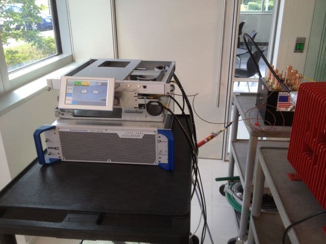
Click to zoom
Application Details
- Equipment Class
- TBC - Licensed Broadcast Station Transmitter
- Date of Grant
- Aug 18, 2014
- Application Purpose
- Original Equipment
- Date of Application
- Jul 31, 2014
- Equipment Note
- 500 Watt UHF ATSC Transmitter
- Frequency Range
- 614.00000000 - 806.00000000
- Company
- Rohde & Schwarz Inc
- Country
- United States
Documents & Files
Document Text
Text extracted from the exhibit documents filed with the FCC. Open a document above to read the original.
Users Manual
R&S ® Tx9 Transmitter System Operating Manual Operating Manual (E9é:2) 2109.9110.02 ─ 07 Broadcasting © 2014 Rohde & Schwarz GmbH & Co. KG Mühldorfstr. 15, 81671 München, Germany Phone: +49 89 41 29 - 0 Fax: +49 89 41 29 12 164 E-mail: [email protected] Internet: www.rohde-schwarz.com Subject to change – Data without tolerance limits is not binding. R&S ® is a registered trademark of Rohde & Schwarz GmbH & Co. KG. Trade names are trademarks of the owners. The following abbreviations are used throughout this manual: R&S ® XYZ1234 is abbreviated as R&S XYZ1234. Sehr geehrter Kunde, Sie haben sich für den Kauf eines Rohde & Schwarz Produk- tes entschieden. Sie erhalten damit ein nach modernsten Fer- tigungsmethoden hergestelltes Produkt. Es wurde nach den Regeln unserer Qualitäts- und Umweltmanagementsysteme entwickelt, gefertigt und geprüft. Rohde & Schwarz ist unter ande- rem nach den Managementsys- temen ISO 9001 und ISO 14001 zertifiziert. Der Umwelt verpflichtet ❙Energie-effiziente, RoHS-konforme Produkte ❙Kontinuierliche Weiterentwicklung nachhaltiger Umweltkonzepte ❙ISO 14001-zertifiziertes Umweltmanagementsystem Dear customer, You have decided to buy a Rohde & Schwarz product. This product has been manufactured using the most advanced meth- ods. It was developed, manufac- tured and tested in compliance with our quality management and environmental manage- ment systems. Rohde & Schwarz has been certified, for exam- ple, according to the ISO 9001 and ISO 14001 management systems. Environmental commitment ❙Energy-efficient products ❙Continuous improvement in environmental sustainability ❙ISO 14001-certified environmental management system Cher client, Vous avez choisi d’acheter un produit Rohde & Schwarz. Vous disposez donc d’un produit fabriqué d’après les méthodes les plus avancées. Le dévelop- pement, la fabrication et les tests de ce produit ont été effec- tués selon nos systèmes de management de qualité et de management environnemental. La société Rohde & Schwarz a été homologuée, entre autres, conformément aux systèmes de management ISO 9001 et ISO 14001. Engagement écologique ❙Produits à efficience énergétique ❙Amélioration continue de la durabilité environnementale ❙Système de management environnemental certifié selon ISO 14001 Certified Environmental System ISO 14001 Certified Quality System ISO 9001 Quality management and environmental management 1171.0200.11 V 05.01 1171020011 ISO-Qualitaets-Zertifikat_1171-0200-11_A4.indd 128.09.2012 10:25:08 1171.0200.22-06.00 Customer Support Technical support – where and when you need it For quick, expert help with any Rohde & Schwarz equipment, contact one of our Customer Support Centers. A team of highly qualified engineers provides telephone support and will work with you to find a solution to your query on any aspect of the operation, programming or applications of Rohde & Schwarz equipment. Up-to-date information and upgrades To keep your instrument up-to-date and to be informed about new application notes related to your instrument, please send an e-mail to the Customer Support Center stating your instrument and your wish. We will take care that you will get the right information. Europe, Africa, Middle East Phone +49 89 4129 12345 [email protected] North America Phone 1-888-TEST-RSA (1-888-837-8772) [email protected] Latin America Phone +1-410-910-7988 [email protected] Asia/Pacific Phone +65 65 13 04 88 [email protected] China Phone +86-800-810-8228 / +86-400-650-5896 [email protected] Contents R&S ® Tx9 3Operating Manual 2109.9110.02 ─ 07 Contents 1 Information about this Manual..............................................................9 2 Safety Instructions...............................................................................11 2.1Safety Instructions for Transmitter Systems and Equipment................................11 2.2General Safety Instructions.......................................................................................12 2.2.1 Safety Instructions.........................................................................................................12 2.3Special Hazard Information........................................................................................19 2.3.1 Hazards from AC Supply Voltage................................................................................. 19 2.3.1.1 AC Power Supply..........................................................................................................19 2.3.1.2 Changing Fuses............................................................................................................19 2.3.2 Hazards from High‑Energy Electric Circuits..................................................................19 2.3.3 Hazards from RF Radiation...........................................................................................20 2.3.3.1 Obligation to Instruct Personnel....................................................................................20 2.3.3.2 RF Shielding..................................................................................................................20 2.3.3.3 Rules When Operating an Amplifier..............................................................................20 2.3.3.4 Rules When Working on an Open Amplifier..................................................................21 2.3.4 Conditions for Assembly Work on Cooling System.......................................................21 2.3.5 Safety Data Sheets for Hazardous Substances............................................................22 3 Introduction to Operation....................................................................23 3.1Operation via R&S TDU900........................................................................................23 3.1.1 Opening Display.....................................................................…
Text truncated - open the document above for the full version.
Attestation Statements
July 31, 2014 Federal Communications Commission Office Of Engineering Technology To Whom It May Concern: ATTESTATION STATEMENT I hereby certify the measurements were executed and test results were recorded in accordance with accepted engineering practices and do constitute an accurate representation of the product performance of the documented TMU91 transmitter. President Greg Best Consulting, Inc. 9223 N. Manning Ave. Kansas City, MO 64157 816-792-2913
Block Diagram
Amp Emission Mask Filter RF Out Exciter TMU91 Transmitter Block Diagram Low Pass Filter
Cover Letter(s)
July 31, 2014 CONFIDENTIALITY REQUEST LETTER TMU91 TRANSMITTER TECHNICAL DATA Pursuant to FCC 0.457(d) and 0.459 of the FCC Rules we are requesting long- term confidentiality due to the fact that the applicant, Rohde & Schwarz, considers certain information to be submitted as trade secret information. Specifically, the schematics and parts lists submitted as exhibits for type certification for the above transmitter are not normally available to anyone outside of company employees. The specific files needing confidentiality are identified as: TCE900 Ctrl Sys part list.pdf TDU900 Part List.pdf TM9-T1 Ampl Kit Part List.pdf PMU901 Parts List.pdf PMU901 Schematics.pdf TCE900 Schematics.pdf TMU9 Configuration Diagrams.pdf The company has gone to great expense to develop the equipment and they could be financially harmed if another competitor were to copy the products using the schematics and parts list information and make them available for sale. The parts lists and schematic information are not supplied with customer documentation. Because of the nature of the schematics and parts lists, redacted documents are not possible. At a minimum, a period of 5 years is necessary for confidentiality for these documents. Regards, Greg Best Consulting, Inc. 9223 N. Manning Ave. Kansas City, MO 64157 816-792-2913
Internal Photos
INTERNAL CONSTRUCTION PHOTOS AMPLIFIER INTERNAL PHOTO #1 AMPLIFIER INTERNAL PHOTO #2 AMPLIFIER INTERNAL PHOTO #3 EXCITER INTERNAL PHOTO
Operational Description
OPERATIONAL DESCRIPTION The R & S model TMU91 transmitter is composed of an exciter, an optional touch-‐screen controller, a single power amplifier module, emission mask filter, and harmonic filter. The exciter unit accepts the transport stream input signal and converts this to an ATSC RF modulated signal. The exciter includes signal processing to improve transmitter linearity performance and frequency response as well as compensating for frequency response issues in the transmission system beyond the transmitter before it reaches the antenna. If dual exciters are used, an exciter switcher is used to select which exciter is routed to the rest of the transmitter. After the exciter, the signal is directed to one power amplifier. Then the signal is routed to a harmonic filter and an emission mask filter to reduce harmonic energy and to ensure adjacent channel emission is compliant with FCC rules. The control unit interfaces with each subsystem within the transmitter and provides monitoring of each function, implements automatic power control, communicates with any remote control system, and provides fault protection for the transmitter. An optional touchscreen display is available. The power amplifier contains the cooling system fans necessary to properly cool all components within the transmitter.
Test Report
1 ROHDE & SCHWARZ MODEL TMU91 ATSC TRANSMITTER TECHNICAL REPORT TABLE OF CONTENTS PAGE Introduction 2 Test Equipment Configuration 3 Transmitter Power Measurements – 500 Watts 4 Emission Mask Compliance Measurements – 500 Watts 5 Filter Attenuation to GPS Frequencies 13 Frequency Stability Measurements 15 Cabinet Radiation Measurements 16 RF Output Power Measurements – 125 Watts 20 Emission Mask Compliance Measurements – 125 Watts 20 Test Equipment 27 Summary and Conclusion 27 Greg Best Consulting, Inc. 9223 N. Manning Ave. Kansas City, MO 64157 816-792-2913 2 TMU91 TRANSMITTER TECHNICAL REPORT The following information is provided to support the technical performance of the R & S TMU91 DTV transmitter. The information is supplied for broadcast service according to applicable portions of Part 74 of the FCC Rules. The information in this report is provided in support of certification that the TMU91 transmitter meets the appropriate requirements identified in the FCC rules and regulations. Measurements outlined below were recorded of spectrum and other data to demonstrate compliance. 1. Power Output Measurements 2. Frequency stability tests versus AC input voltage and temperature 3. Measurements to demonstrate the transmitter meets the DTV emission mask as specified in FCC Rule 74.794 (a) (2) (ii) and 74.794 (b) (1). 4. Measurement of cabinet radiation for spurs and harmonics as specified in FCC Rule 2.1053 and Rule 2.1057 Measurements for power output and emission mask compliance were conducted at power output levels of both 500 watts and 125 watts. This is the range for which type certification is sought. The test equipment used for the measurements is listed at the end of this document. All equipment was within its calibration period. 3 Note: The coupling factor of directional coupler #2 was determined to be 42.83 dB at channel 36. FIGURE 1—TEST EQUIPMENT CONFIGURATION Exciter Transmitter PA Directional Coupler #1 Emission Mask Filter Directional Coupler #2 Bandstop Filter R & S FSU8 R & S NRP-Z91 Power Sensor High Pass Filter Dummy Load Personal Computer 4 RF Power Output Measurements The equipment was configured as shown in Figure 1. The coupling factor of directional coupler #2 was calibrated at the center frequency of the channel 36 DTV signal of 605 MHz. The coupling value was 42.83 dB. Average power was measured with the R & S NRP-Z91 power sensor connected to the directional coupler and displayed on the personal computer using the Power Viewer program. The indicated reading with the offset from the directional coupler is shown below. Figure 2—Power Meter Reading at Nominal Transmitter Power Calculation of Output Power: An offset of 42.828 dB from the directional coupler was added to the reading on the Power Viewer program. The actual value of 14.17 dBm was measured using the NRP- Z91 power sensor and the offset value of 42.83 dB was added to the directional coupler coupling value to display the correct value of 57.0 dBm or 500 watts. With this operating state, measured transmitter final amplifier voltage was 29.7 VDC and final amplifier current was 55.7 Amps. The power supply voltage for each amplifier was multiplied by the current for each amplifier to obtain the total DC power of 1654 W for the final amplifier stage. 5 Emission Mask Compliance To determine conducted radiation emission mask compliance, the test equipment configuration shown on Figure 1 was used. For adjacent channel and harmonic energy measurements, the R & S FSU8 spectrum analyzer was used. The transmitter was tested for compliance with the stringent emission mask as specified in FCC rule 74.794 (a) (2) (ii). The IEEE 2008-1631 Recommended Practice On 8-VSB Digital Television Transmission Compliance Measurement was used as the test measurement methodology. The first part of the emission mask compliance tests measured the adjacent channel emission and the second part of the tests measured the harmonic and spurious energy. The transmitter was energized at 500 watts on Channel 36 (center frequency of 605 MHz) as measured at the output of Directional coupler #2 using the R & S NRP-Z91 power sensor and a reference was established on the FSU8 spectrum analyzer (using the channel power measurement mode). The bandstop filter insertion loss (including input and output cables loss) versus frequency response was previously determined using the FSU8 spectrum analyzer and tracking generator combination. The insertion loss at the center of each of the twelve 500 kHz segments either side of the main channel was tabulated. The bandstop filter response is shown as Figure 3. The tabulated attenuation versus frequency has been indicated in the next section with the table of measured emission values. Figure 3 Bandstop Filter Response 6 The noise floor of the spectrum analyzer in the adjacent channels was found and from that value, the minimum RF sample level was determined (assuming the transmitter exactly met the emission mask requirements identified in the FCC rules). The actual RF sample level was well above the required minimum RF sample so plenty of margin was available with the test configuration used. The minimum RF sample value and actual RF sample values are contained in the emission mask measurement table on the following page The transmitter was energized at 500 W and optimized for linearity. The 6 MHz DTV channel power was first measured for the channel 36 signal. This data was recorded in the table on the following page. Then the twelve 500 kHz segments on both sides of the channel 36 signal were measured. Leaving the spectrum analyzer attenuator set at the same value as the 6 MHz channel power measurement, the closest four 500 kHz segments on either side of the channel 36 signal were measured without the use of the bandstop filter because those signals were above the noise floor of the FSU8 spectrum analyzer with the existing attenuator setting. Spectrum analyzer screen captures were made for the upper and lower side…
Text truncated - open the document above for the full version.
Contact Information
Applicant
Erik Balladeres
Technical Contact
Greg Best Consulting, Inc.Greg Best
[email protected]816-792-2913
9223 N. Manning Avenue · Kansas City, Missouri · United States
Technical Specifications
| # | Rule Parts | Frequency Range | Power Output | Emission | Tolerance |
|---|---|---|---|---|---|
| 2 | 74 | 614 MHz - 806 MHz | 500 W | 6M00K1D | 1000 Hz |
Other Applications from Rohde & Schwarz Inc
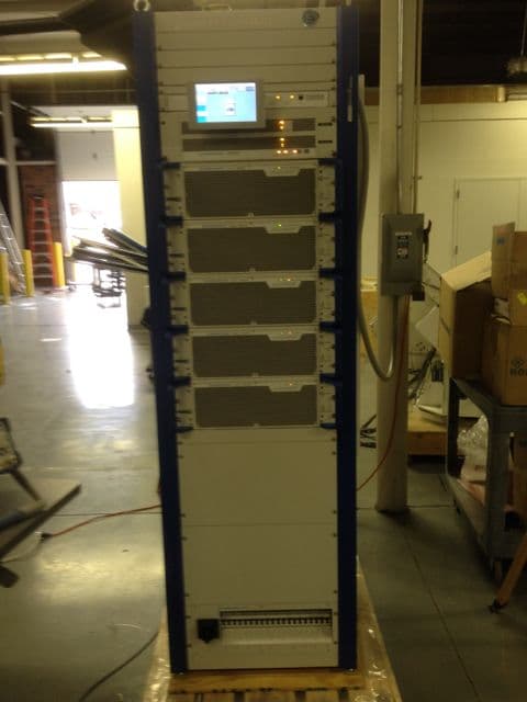
HFLTMU925
Jul 21, 2014UHF DTV ATSC 1KW TO 2.5 KW TRANSMITTER FAMILY
Equipment Class
TBC - Licensed Broadcast Station Transmitter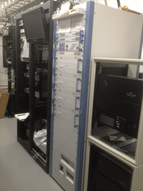
HFLNV830X
May 22, 2012UHF 1.8kW maximum Digital TV transmitter
Equipment Class
TBC - Licensed Broadcast Station Transmitter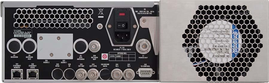
HFLSLV8000
Jan 05, 2011SLV8000 Low Power Transmitter
Equipment Class
TBC - Licensed Broadcast Station Transmitter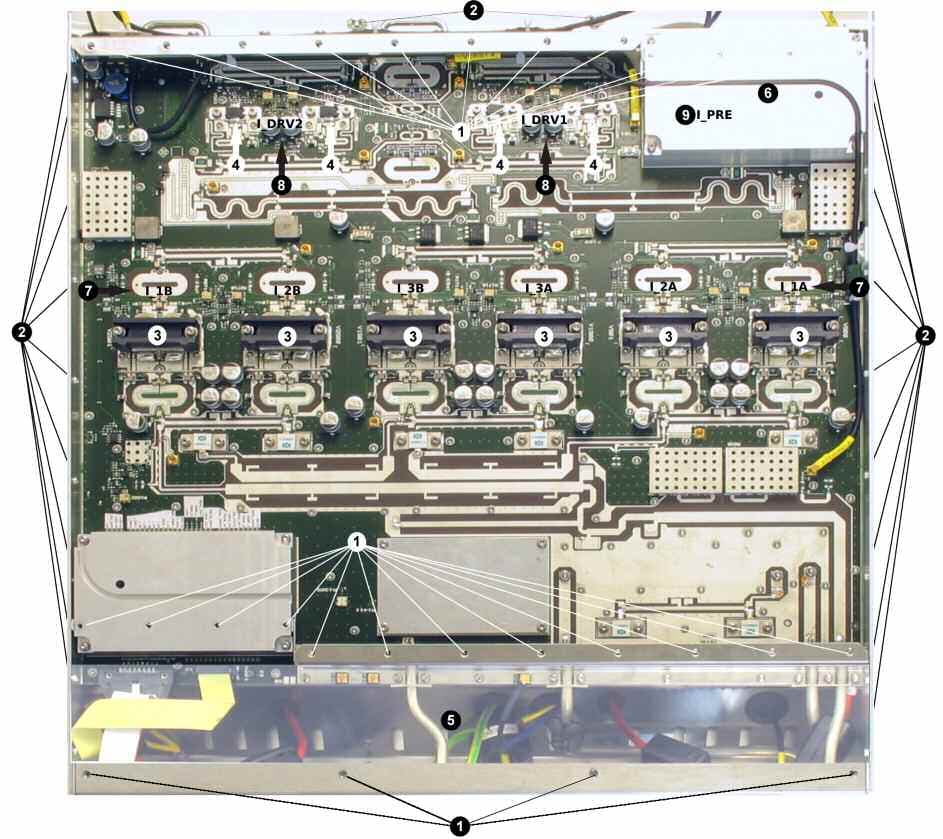
HFLSCV8000
May 04, 2010SCV8000
Equipment Class
TBC - Licensed Broadcast Station Transmitter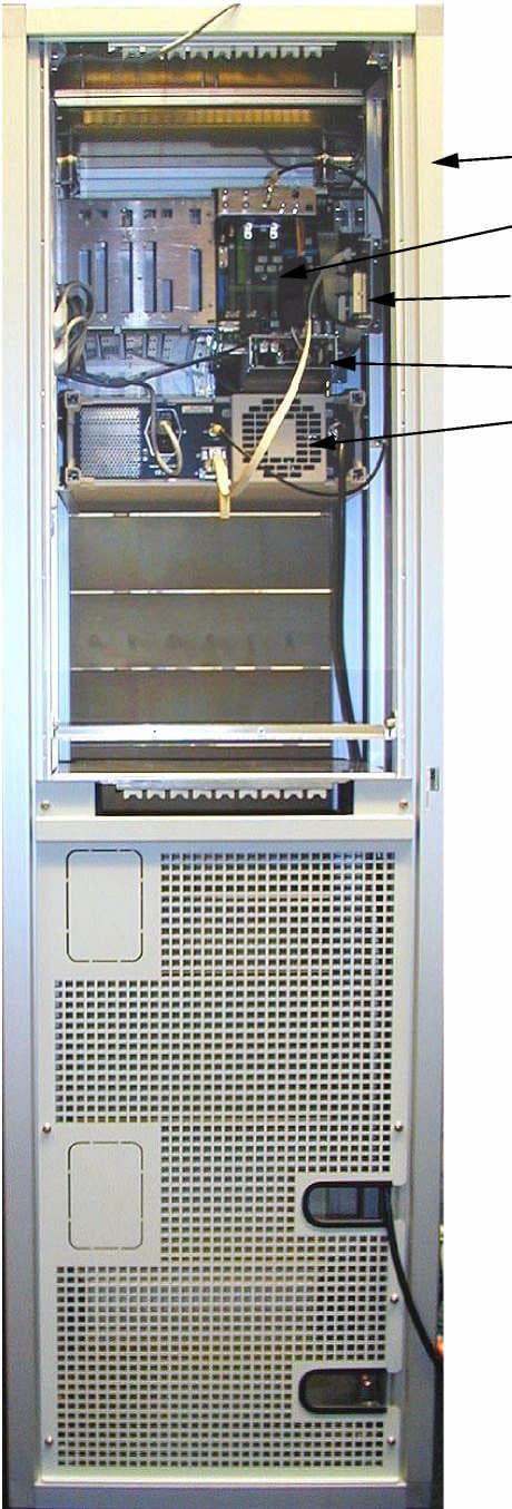
HFLSV7000FLO
Oct 11, 2007DMQ-T Sender (Transmitter)
Equipment Class
TNB - Licensed Non-Broadcast Station Transmitter