HH4TF5-RXHEART RATE VARIABILITY MONITER
MIE Medical Research Ltd
Click to zoom
Application Details
- Equipment Class
- CYY - Communications Receiver used w/Pt 15 Transmitter
- Date of Grant
- Jun 23, 2003
- Application Purpose
- Original Equipment
- Date of Application
- Jun 23, 2003
- Equipment Note
- HEART RATE VARIABILITY MONITER
- Frequency Range
- 914.50000000 - 914.50000000
- Company
- MIE Medical Research Ltd
- Country
- United Kingdom
Documents & Files
Document Text
Text extracted from the exhibit documents filed with the FCC. Open a document above to read the original.
Users Manual
Doc 125-05 System for Telemetric, Non-invasive, Computer-aided Evaluation of Heart Rate Variability USER MANUAL © 2001-2003, Advanced Medical Diagnostics Group, Ltd. ® (c) 2001-2003 Advanced Medical Diagnostics Group, Ltd Doc 125-06 1 VariaCardio ® TF5 Manual Table of contents: 1.BEFORE YOU BEGIN 3 1.1 WARNINGS 4 DISCLAIMER OF WARRANTY 6 1.2. VARIACARDIO TF5 HELP LINE 6 1.3. CARING FOR THE VARIACARDIO TF5 SYSTEM 6 1.4. TECHNICAL AND SAFETY NOTES 8 2. GENERAL DESCRIPTION 9 2.1. PARTS OF THE VARIACARDIO TF5 9 2.1.1. CHEST BELT WITH UHF-TRANSMITTER 10 2.1.2. UHF-RECEIVER 12 2.2. OTHER COMPONENTS / PRINTER 13 2.3. AC/DC ADAPTER FOR A TRANSMITTER BATTERY AND GUIDELINES FOR ITS CHARGING 14 2.4. PRODUCTION, TESTING, WARRANTY AND TECHNICAL SUPPORT 14 3. VARIACARDIO TF5 PROGRAM PRINCIPLES & CONTROL 16 3.1. WHAT THE SWITCH BUTTONS MEAN 16 3.2. WHAT THE LED DIODES MEAN 16 3.3. WHAT IS THE NORMAL OPERATION SETTING 16 4. OPERATING THE VARIACARDIO TF5 17 4.1. HOW TO INSTALL THE SOFTWARE 17 I NSTALLATION WIZARD 18 4.2. HOW TO LAUNCH THE APPLICATION 21 4.3. HOW TO ADJUST THE BELT 22 4.4. HOW TO ADJUST THE COMMUNICATION RECEIVER/COMPUTER: 22 4.5. HOW TO ENTER THE DATA AND/OR TO CONTROL THE SYSTEM 23 5. CLINICAL USE OF THE SYSTEM: DATABASE 24 5.1. BEFORE WE START 24 5.2. HOW TO START THE PROGRAM 24 5.3. THE BASIC OPERATION SCREEN 25 5.4. DATABASE: HOW TO FIND A SUBJECT 27 5.5. DATABASE: HOW TO ADD A NEW SUBJECT RECORD 27 5.6. DATABASE: HOW TO DELETE A RECORD / SUBJECT 29 5.7. DATABASE: HOW TO CHANGE THE DATABASE / CREATE A NEW DATABASE 29 (c) 2001-2003 Advanced Medical Diagnostics Group, Ltd Doc 125-06 2 5.8. DATABASE: HOW TO SET THE DATABASE AS DEFAULT 30 5.9. DATABASE: HOW TO IMPORT DATA OBTAINED BY PREVIOUS MODELS 30 5.10. DATABASE: HOW TO COMPACT THE DATABASE 30 5.11. LICENSE, HARDLOCK, DATA PROTECTION & BUSINESS ISSUES 31 5.12. HOW TO SEND RECORDS AND PROTOCOLS VIA E-MAIL 31 5.13. HOW TO EXPORT AND IMPORT HRV RECORDS 32 6. CLINICAL USE OF THE SYSTEM: MEASUREMENTS 33 6.1. MEASUREMENTS: SPECTRAL TEST MEASURING SCREEN 33 6.2. MEASUREMENTS: HOW TO PERFORM MEASUREMENT 34 6.3. HOW TO BROWSE/EDIT THE DATA 38 6.3.1. ECG BROWSER 41 7. CLINICAL USE OF THE SYSTEM: ANALYSIS 43 7.1. HRV BASICS. HOW TO UNDERSTAND THE PRINCIPLES OF ANALYSIS 43 7.2. HRV BASICS. HOW THE R-R INTERVALS MEASUREMENT WORKS 45 7.3. HRV BASICS. HOW TO UNDERSTAND THE 3D RESULTS 46 7.4. ANALYSIS. HOW TO PERFORM THE ANALYSIS 48 7.4.1. BASIC ANALYSIS SCREEN. 3D RUNNING SPECTRA GRAPH 48 7.4.2. BASIC ANALYSIS SCREEN. STATISTICAL TABLE 50 7.4.3. BASIC ANALYSIS SCREEN. GRAPHICAL TABLE 50 7.4.4. BASIC ANALYSIS SCREEN. RESUME 51 7.4.5. BASIC ANALYSIS SCREEN. EXPORT OF NUMERICAL RESULTS 51 7.5. ANALYSIS. MEDICAL REPORT AND HOW TO OBTAIN IT 52 8. BATTERY OF SHORT CARDIOVASCULAR REFLEX TESTS AS PROPOSED BY EWING (SO-CALLED ‘EWING BATTERY’) 53 8.1. EWING BATTERY: INTRODUCTION 53 8.2. HOW TO PERFORM THE EWING’S TEST BATTERY 53 8.2.1. EWING BATTERY: HOW TO PERFORM THE DEEP BREATHING TEST 55 8.2.2. EWING BATTERY: HOW TO PERFORM THE VALSALVA MANEUVER 57 8.2.2. EWING BATTERY: HOW TO PERFORM THE ORTHOSTATIC TEST 58 9.1. SOME PRACTICAL EXAMPLES 60 9.2. APPLICATION NOTES 61 Y OUR NOTES 63 The VariaCardio TF5 system is manufactured and distributed exclusively by Advanced Medical Diagnostics Group, Ltd, UK and its partners. © Copyright 2001-2003, Advanced Medical Diagnostics Group, Ltd. All rights reserved. (c) 2001-2003 Advanced Medical Diagnostics Group, Ltd Doc 125-06 3 1. Before You Begin Thank you for purchasing this VariaCardio TF5 system. The operating instructions that are found in this manual should be followed carefully to ensure many years of reliable service. Please read these instructions thoroughly before using the VariaCardio TF5 system. The operating instructions should allow the average user to become familiar and proficient in the review and editing of patient records generated by the VariaCardio TF5 system. This manual does not teach the operator to recognise or to interpret the records. That information is beyond the scope of this manual. An overview is described later in this document. Manufactured by: MIE Medical Research, Ltd. for Advanced Medical Diagnostics Group, Ltd. 6, Wortley Moor Road, Leeds, LS12 4JF United Kingdom Phone: +44 (0)113 279 1010 Fax: +44 (0)113 2310 820 Website: http://www.amdgmedical.com E-Mail: [email protected] Your VariaCardio TF5 system Serial Number: _____________________ (c) 2001-2003 Advanced Medical Diagnostics Group, Ltd Doc 125-06 4 1.1 Warnings • Do not operate the VariaCardio TF5 system on a patient with a heart pacemaker or any other telemetrically (UHF range) programmable/controllable device. • If a patient connected to the VariaCardio TF5 system is to be defibrillated, the leads must be removed from the patient before defibrillation. • There are no user serviceable parts. • FCC Part 15 requirement:- This device requires a shielded interface cable (RS232) to ensure compliance. • The operating UHF frequency range of 869.7 MHz (914.5 MHz USA only) used for wireless ECG/RR data transfer is considered for general industrial, scientific and medical use (‘ISM band’). Therefore, it might casually be possible that disturbance caused by another wireless device working on the same operating frequency occurs. This situation means in no way any hazard for patient. However, it might be necessary to use another operating frequency for your VariaCardio TF5 to work correctly. • User changes or modifications not expressly approved by AMDG/MIE could void the user’s authority to operate the VariaCardio TF5. Exclusions: • Do not store or operate the VariaCardio TF5 system in a sterile, wet, damp or dusty environment. • Do not use the system in areas with explosive and / or inflammable gases. • Do not store or operate the system in direct sunlight • Only use antennae provided with the VariaVardio TF5 system. Regulatory: • FDA: This instrument is a Class II, Type B Applied Part device. • CE: This device is a class 2a device w…
Text truncated - open the document above for the full version.
Cover Letter(s)
Tel: Fax: E-mail: Web: Reg: +44 (0)113 279 3710 +44 (0)113 231 0820 [email protected] http://www.mie-uk.com 1701634 Directors: Dr. M.I. Ellis, B.Sc., Ph.D., C.Eng Mrs. V. Ellis V.A.T. Number: GB 387 9339 85 Registered Office: 6 Wortley Moor Rd LEEDS West Yorkshire, LS12 4JF United Kingdom Federal Communications Commission Authorization and Evaluation Division Confidentiality Request regarding application for certification of FCC ID: HH4TF5-RX Pursuant to Sections 0.457 and 0.459 of the Commission’s Rules, we hereby request confidential treatment of information accompanying this application as outlined below: Operational theory Block diagram Schematic diagram Parts List The above materials contain trade secrets and proprietary information not customarily released to the public. The public disclosure of these materials may be harmful to the applicant and provide unjustified benefits to its competitors. The applicant understands that pursuant to Section 0.457 of the Rules, disclosure of this application and all accompanying documentation will not be made before the date of the Grant for this application. Sincerely,
External Photos
ExternalPhotoBackPanelReceiver
ID Label/Location Info
TF5 FCC ID Label Location
ID Label/Location Info
VARIACARDIO TF5-RECEIVER TestedToComplywithFCCStandard FCCCFR47,parts15.109 Forunintentionalradiators RXFCCID:HH4TF5-RX MadeinEnglandby medicalresearchltd. 6WortleyMoorRoad,LeedsLS124JF.UK. Tel:+44(0)1132793710Fax:+44(0)1132310820 E-Mail:[email protected]:www.mie-uk.com SupplyVoltage:12VDC/50mAR-Rint:1ms± SerialNo:Frequency:914.5MHz Nottobeusedina sterileenvironment Referto manual ! FCCIDLabelArtworkforthe TF5Receiver Title: DrawingNo.:0183IssueNo.:03IssueDate:15-MAY-2003 MIEAuthorizationSignature:............................................... ThisdevicecomplieswithPart15oftheFCCRules. Operationissubjecttothefollowingtwoconditions: (1)Thisdevicemaynotcauseharmfulinterference, and(2)Thisdevicemustacceptanyinterference received,includinginterferencethatmaycause undesiredoperation.
Internal Photos
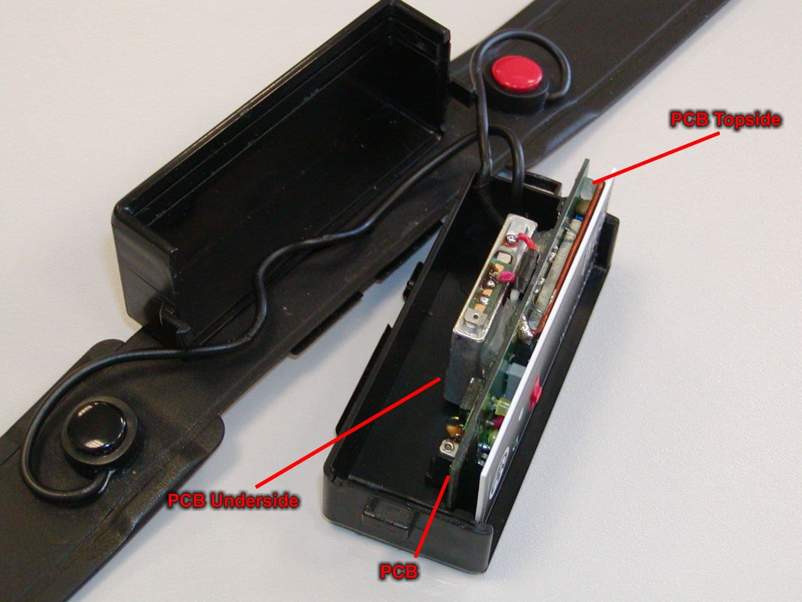
RX Component side Rx Track Side
Test Report
SGS United Kingdom Ltd Unit 10, Bowburn South Industrial Estate, Bowburn, Durham DH6 5AD Tel +44 (0)191 377 2000 Fax +44 (0)191 377 2020 Registered in England No. 1193985 Rossmore Business Park, Ellesmere Port, Cheshire CH65 3EN www.sgs.com Member of SGS Group (Société Générale de Surveillance) Electromagnetic Compatibility Test of: Heart Rate Variability Monitor Model Number: TF5 Applicant: MIE Medical Research Ltd. Test Type: Compliance Test Specification: FCC CFR47 October 1999, parts 15.107, 15.109 for unintentional radiators, 15.207, 15.209 and 15.249 for intentional radiators SGS Serial Number: DUR23903/FCC/ST/02 Date of Receipt: 21 st February 2002, 24 th February 2003, 15 th May 2003 Date of Test(s): 26 th March 2002 – 26 th February 2003, 2 nd June – 4 th June 2003 Date of Issue: 4 rd June 2003 Issue Number: 3 This report refers only to the sample submitted for test. This report shall not be reproduced except in full without the written approval of the testing laboratory. Test EngineerAuthorised Signatory S. ThompsonA. Reynard Technical Manager TEST REPORT Page 2 of 19 Issue Date: 4 rd June 2003 SGS Serial Number: DUR23903/FCC/ST/02 Issue Number: 3 CONTENTSPage Number 1. Client Information ........................................................................................................................... 3 2. Details Of Test Laboratory............................................................................................................. 3 3. Equipment Under Test (EUT)......................................................................................................... 4 3.1 Identification Of EUT.................................................................................................................................................. 4 4. Test Specification, Methods and Procedures.............................................................................. 4 4.1 Test Specification(s) .................................................................................................................................................. 4 4.2 Purpose Of Test ........................................................................................................................................................ 4 4.3 Methods and Procedures............................................................................................................................................ 5 5. Deviations or Exclusions from the Test Specifications.............................................................. 6 6. Operation of the EUT During Testing / Configuration and Peripherals .................................... 7 6.1 Operating Mode and Environmental Conditions ......................................................................................................... 7 6.2 Configuration and Peripherals..................................................................................................................................... 7 7. Test Results .................................................................................................................................... 7 7.1 General Comments.................................................................................................................................................... 7 7.2 Modifications Made to the EUT.................................................................................................................................. 7 7.3 Summary of Test Results............................................................................................................................................ 8 7.4Conducted Emissions Test Results - Receiver ..................................................................... 9 7.5Conducted Emissions Test Results - Transmitter .............................................................. 12 7.6Radiated Emissions Test Results ......................................................................................... 15 TEST REPORT Page 3 of 19 Issue Date: 4 rd June 2003 SGS Serial Number: DUR23903/FCC/ST/02 Issue Number: 3 1. Client Information Company Name: MIE Medical Research Ltd. Address: 6 Wortley Moor Road Leeds Yorkshire LS12 4JF Contact Person: Suzanne Banner Telephone: +44 (0) 113 279 3710 Facsimile: +44 (0) 113 231 0820 2. Details Of Test Laboratory Company Name: SGS UK Ltd. UKAS Accreditation Number: 1116 Address: South Industrial Estate, Bowburn, Co. Durham, DH6 5AD. Contact Persons: Alan Reynard Telephone: +44 (0) 191 377 2000 Facsimile: +44 (0) 191 377 2020 TEST REPORT Page 4 of 19 Issue Date: 4 rd June 2003 SGS Serial Number: DUR23903/FCC/ST/02 Issue Number: 3 3. Equipment Under Test (EUT) 3.1Identification Of EUT Model Number: TF5 Unique Identifier: US version 94/99 Description of EUT: The EUT is a Heart Rate Variability Monitor consisting of: - UHF Transmitter UHF Receiver Egston Power Supply Unit (Model: N2GFMW3 S/N: 01C00046) Supply Voltage: UHF Transmitter: 3.7V Lithium Battery UHF Receiver: 9-12V DC via AC/DC Adaptor Egston Power Supply Unit: 110V AC Classification: 914MHz Intentional Radiator Ports present: UHF Transmitter: Battery Charge Port UHF Receiver: 9-12V DC Adaptor and RS232 (both specified by client <3m) Egston Power Supply Unit: 110V AC Mains and 12V DC output (specified by client <3m) Accessories Supplied: None 4. Test Specification, Methods and Procedures 4.1Test Specification(s) Specification(s)Title FCC CFR 47 : October 1999 Parts 15.107, 15.109, 15.207, 15.209 and 15.249 Code Of Federal Regulations 4.2Purpose Of Test To perform the relevant tests and assess the product for compliance with the above specification, so that the manufacturer can obtain certification. TEST REPORT Page 5 of 19 Issue Date: 4 rd June 2003 SGS Serial Number: DUR23903/FCC/ST/02 Issue Number: 3 4.3Methods and Procedures The standards listed on the previous page refer to the following tests: - CFR 47 ClauseTest 15.107Conducted Emissions unintentional rad…
Text truncated - open the document above for the full version.
Contact Information
Applicant
A Mey
Test Firm
SGS United Kingdom Ltd.Stephen Thompson
Technical Specifications
| # | Rule Parts | Frequency Range | Power Output |
|---|---|---|---|
| 1 | 15B | 914.5 MHz - 914.5 MHz | - |
Other Applications from MIE Medical Research Ltd
HH4TF5-TX
Jul 06, 2003HEART RATE VARIABILITY MONITER
Equipment Class
DXX - Part 15 Low Power Communication Device TransmitterHH45SMMT8RX
Aug 04, 1988CYY - Communications Receiver used w/Pt 15 Transmitter
Equipment Class
CYY - Communications Receiver used w/Pt 15 Transmitter